JP2005295345A - Color scanner device - Google Patents
Color scanner device Download PDFInfo
- Publication number
- JP2005295345A JP2005295345A JP2004109408A JP2004109408A JP2005295345A JP 2005295345 A JP2005295345 A JP 2005295345A JP 2004109408 A JP2004109408 A JP 2004109408A JP 2004109408 A JP2004109408 A JP 2004109408A JP 2005295345 A JP2005295345 A JP 2005295345A
- Authority
- JP
- Japan
- Prior art keywords
- image data
- color
- luminance
- area
- unit
- Prior art date
- Legal status (The legal status is an assumption and is not a legal conclusion. Google has not performed a legal analysis and makes no representation as to the accuracy of the status listed.)
- Pending
Links
- 238000012937 correction Methods 0.000 claims abstract description 53
- 230000008859 change Effects 0.000 claims description 13
- 238000006243 chemical reaction Methods 0.000 description 12
- 230000003287 optical effect Effects 0.000 description 8
- 238000000034 method Methods 0.000 description 7
- 230000008569 process Effects 0.000 description 5
- 238000010586 diagram Methods 0.000 description 2
- 238000000926 separation method Methods 0.000 description 2
- 241000255969 Pieris brassicae Species 0.000 description 1
- 239000003086 colorant Substances 0.000 description 1
- 230000006866 deterioration Effects 0.000 description 1
- 230000000694 effects Effects 0.000 description 1
- 230000006870 function Effects 0.000 description 1
- 238000009434 installation Methods 0.000 description 1
- 230000009467 reduction Effects 0.000 description 1
- 230000004044 response Effects 0.000 description 1
Images


Landscapes
- Image Processing (AREA)
- Facsimile Image Signal Circuits (AREA)
- Color Image Communication Systems (AREA)
Abstract
Description
本発明は、原稿をカラー画像データとして取得可能なカラースキャナ装置に関する。 The present invention relates to a color scanner apparatus that can acquire a document as color image data.
スキャナ装置において、例えば、文字と写真が混在する原稿の画像データを取得する場合、隣接する画素の緩やかな輝度変化を反映した画像処理を施した画像データとすることで、写真部分が鮮明な画像データを取得することが可能となる。しかしながら、このように画像処理は、文字のエッジがぼやけた状態となるため文字が不鮮明となる。 In a scanner device, for example, when acquiring image data of a manuscript in which characters and photographs are mixed, image data that has undergone image processing that reflects a gradual change in luminance of adjacent pixels can be used to obtain a clear image of the photographic part. Data can be acquired. However, in this image processing, since the edge of the character is blurred, the character becomes unclear.
逆に、文字部分が鮮明な画像データを得るために、例えば、文字のエッジが強調されるような画像処理を行うと、隣接する画素の緩やかな輝度変化が反映されなくなり写真部分が不鮮明な画像データとなる。 On the contrary, in order to obtain image data in which the character portion is clear, for example, when image processing that emphasizes the edge of the character is performed, an image in which the gradual luminance change of adjacent pixels is not reflected and the photographic portion is unclear It becomes data.
すなわち、文字部分を鮮明にすることと写真部分を鮮明にすることとは、トレードオフの関係にあり、文字と写真とがともに鮮明になる画像処理を行うことは困難であった。 That is, there is a trade-off between making the character portion clear and the photo portion clear, and it has been difficult to perform image processing in which both the character and the photo are clear.
上記問題点に対する対策として、取得した画像データに対して、文字領域と非文字領域で異なる補正を行うことが考えられる。例えば、後掲の特許文献1に、画像データを構成する画素の隣接方向の輝度変化量を検出し、画像データを文字領域と写真等の非文字領域とに領域分離する技術が提案されている。
特許文献1に記載の技術をスキャナ装置に採用して、画像データの文字領域に対して文字のエッジを強調する画像処理を行い、非文字領域に対して隣接する画素で緩やかな輝度変化を反映させる画像処理を行うには、文字領域と非文字領域を正確に分離する必要がある。
The technique described in
しかし、このような領域分離を正確に行うためには、画像読取手段が備えるCCD(Charge Coupled Device)等の撮像素子が出力する信号のS/N比を高める必要がある。このように撮像素子が出力する信号のS/N比を高める信号処理を行うことは、結果的に各画素の輝度を変化させることになるため、上記処理を行った画像データは、上記と同様に非文字領域が不鮮明になる。すなわち、文字領域と非文字領域とを正確に分離するために出力信号のS/N比を高める処理を行った時点で、非文字領域の画質が低下してしまうのである。 However, in order to perform such region separation accurately, it is necessary to increase the S / N ratio of a signal output from an image sensor such as a CCD (Charge Coupled Device) provided in the image reading unit. Since the signal processing for increasing the S / N ratio of the signal output from the image sensor in this way results in a change in the luminance of each pixel, the image data subjected to the above processing is the same as described above. The non-character area becomes unclear. That is, when the process for increasing the S / N ratio of the output signal is performed in order to accurately separate the character area and the non-character area, the image quality of the non-character area is degraded.
また、カラー用CCDを使用するカラースキャナ裝置では、モノクロ用CCDに比べて出力信号のS/N比が低いため、S/N比を高める信号処理を行った場合に、非文字領域の画質の劣化が顕著になる。このため、RGBの色成分のうちの1つから、モノクロ画像データを取得する場合は、非文字領域が鮮明な画像データを取得することがより困難であった。 Further, in a color scanner apparatus using a color CCD, the S / N ratio of the output signal is lower than that of a monochrome CCD. Therefore, when signal processing for increasing the S / N ratio is performed, the image quality of the non-character area is improved. Deterioration becomes remarkable. For this reason, when obtaining monochrome image data from one of the RGB color components, it is more difficult to obtain image data with a clear non-character area.
本発明は、上記従来の事情に基づいて提案されたものであって、カラースキャナ装置において、モノクロ画像データを取得する場合に、モノクロ画像の文字領域と非文字領域とがともに鮮明な画像データを得ることができるカラースキャナ装置を提供することを目的とする。 The present invention has been proposed on the basis of the above-described conventional circumstances, and when a monochrome image data is acquired in a color scanner device, image data in which both a character area and a non-character area of a monochrome image are clear is obtained. An object of the present invention is to provide a color scanner device that can be obtained.
本発明は、上記目的を達成するために以下の手段を採用している。 The present invention employs the following means in order to achieve the above object.
まず、本発明は、原稿を単位領域ごとに光学的の読み取り、複数の色成分に分離した画像データを取得するカラー画像読取手段と、前記画像データ中の画素の輝度変化に基づいて文字領域と非文字領域とを判別する領域判別手段と、前記原稿をカラー画像データとして取得するかモノクロ画像データとして取得するかを選択する色種選択手段とを備えるカラースキャナ装置を前提としている。 First, according to the present invention, a color image reading unit that optically reads a document for each unit region and acquires image data separated into a plurality of color components, a character region based on a luminance change of a pixel in the image data, and It is premised on a color scanner device including area determination means for determining a non-character area and color type selection means for selecting whether the original is acquired as color image data or monochrome image data.
このカラースキャナ装置において、本発明は、前記色種選択手段がモノクロ画像データを選択しているときに、少なくとも1つの色成分の画像データに対して、各画素の輝度を予め設定した所定量だけオフセットさせる輝度補正を行う第1の輝度補正手段を備える。 In this color scanner device, the present invention provides a predetermined amount of luminance of each pixel for image data of at least one color component when the color type selection means selects monochrome image data. First luminance correction means for performing luminance correction for offsetting is provided.
また、前記領域判別手段は、前記第1の輝度補正手段が輝度補正を行った画像データに基づいて前記領域判別を行い、画像処理手段は少なくとも1つの他の色成分の画像データに対して、前記領域判別手段が判別した領域種に応じた画像処理を行い、モノクロ画像データとして出力する。 In addition, the area determination unit performs the area determination based on the image data on which the first luminance correction unit has corrected the luminance, and the image processing unit performs the determination on the image data of at least one other color component. Image processing corresponding to the region type determined by the region determination means is performed and output as monochrome image data.
上記構成によれば、カラー画像読取装置が取得する画像データのうち、1つの色成分の画像データを文字領域と非文字領域との分離に好適な補正を施し、当該画像データに基づいて判別した領域種に応じた画像処理を、S/N比が劣化していない他の色成分の画像データに対して行うことでモノクロ画像データを取得するため、文字領域と非文字領域とがともに鮮明なモノクロ画像データを取得することが可能となる。 According to the above configuration, the image data of one color component out of the image data acquired by the color image reading device is subjected to correction suitable for separation between the character area and the non-character area, and is determined based on the image data. Monochrome image data is obtained by performing image processing according to the region type on image data of other color components whose S / N ratio has not deteriorated, so that both the character region and the non-character region are clear. Monochrome image data can be acquired.
また、カラー画像読取手段による原稿の読取と、上述の処理とは並行して行うことができるため、短時間でモノクロ画像データを取得することが可能であり、全画像データをメモリ等の記憶手段に格納する必要がなく、大容量のメモリも必要としない。 In addition, since the reading of the original by the color image reading unit and the above-described processing can be performed in parallel, it is possible to acquire monochrome image data in a short time, and all the image data is stored in a storage unit such as a memory. It does not need to be stored in the memory and does not require a large amount of memory.
さらに、上記構成に加えて、上記他の色成分の画像データに対して、各単位領域内の各画素の輝度を、当該単位領域ごとに導出される量だけオフセットさせる輝度補正を行う第2の輝度補正手段を備え、前記画像処理手段が、前記第2の輝度補正手段が輝度補正を行った画像データに対して、前記領域判別手段が判別した領域種に応じた画像処理を行うことで前記モノクロ画像データを出力する構成とすることが好ましい。これにより、上記画像処理は、S/N比が改善された画像データに対して行われることになるため、より鮮明なモノクロ画像データを取得することができる。 Further, in addition to the above-described configuration, a second luminance correction is performed to offset the luminance of each pixel in each unit region by an amount derived for each unit region with respect to the image data of the other color components. Brightness correction means, and the image processing means performs image processing according to the area type determined by the area determination means on the image data corrected by the second brightness correction means. Preferably, monochrome image data is output. Accordingly, the image processing is performed on the image data with an improved S / N ratio, so that clearer monochrome image data can be acquired.
本発明によれば、カラースキャナ装置から、モノクロ専用のスキャナ装置と遜色の無い良好なモノクロ画像データを取得することが可能となる。 According to the present invention, it is possible to acquire, from a color scanner device, good monochrome image data that is not inferior to a monochrome-only scanner device.
以下、本発明の実施の形態を図面にしたがって詳細に説明する。図1は、本発明に係るカラースキャナ装置10の概略機能ブロック図である。
Hereinafter, embodiments of the present invention will be described in detail with reference to the drawings. FIG. 1 is a schematic functional block diagram of a
図1に示すように、本発明のカラースキャナ装置10は、原稿に照射した線状光の反射光を受光することで、RGB(赤、緑、青)の3つの色成分に分離した画像データとして取得するカラー画像読取手段1と、カラー画像読取手段1が取得した各画像データに、例えば、ガンマ補正、拡大、縮小等の各種画像処理を施し、当該画像データをネットワークや他のインターフェイスを介して装置10の外部に出力する画像処理手段6とを備える。また、図示しない操作部からの指示により、上記画像データをカラー画像データとして取得するのか、モノクロ画像データとして取得するのかを選択する色種選択手段4、及び、上記画像データ中の文字領域と非文字領域を判別する領域判別手段5を備える。なお、第1の輝度補正手段2、及び第2の輝度補正手段3については後述する。
As shown in FIG. 1, the
上記カラー画像読取手段1は、上記RGBの3色にそれぞれ対応する画像データを生成して出力する赤画像データ出力部1a、緑画像データ出力部1b、及び青画像データ出力部1cを備えている。各画像データ出力部1a、1b、1cは、上記反射光が受光できるように線状に複数個が配置され、上記反射光からそれぞれの色成分だけを読み取るCCD等の撮像素子と、当該撮像素子が受光した光の輝度に応じて出力する出力信号(アナログ)をA/D変換処理(アナログ−ディジタル変換処理)し、画像データを生成するA/Dコンバータとから構成される。
The color
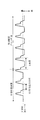
図2は、例えば、赤画像データ出力部1aが備える撮像素子の画素の一部(光を受光できない光学的黒画素を含む隣接する8個の画素)から順次出力された出力信号を示している。なお、左方の3画素分のデータが光学的黒画素の出力信号であり、右方の5画素分のデータが有効画素の出力信号である。また、図中に1画素として示した期間のうち、信号出力期間11は各撮像素子が信号を出力している期間である。 FIG. 2 shows, for example, output signals sequentially output from some of the pixels of the image sensor included in the red image data output unit 1a (eight adjacent pixels including optical black pixels that cannot receive light). . Note that the data for the three pixels on the left is the output signal of the optical black pixel, and the data for the five pixels on the right is the output signal of the effective pixel. Of the periods indicated as one pixel in the figure, the signal output period 11 is a period in which each image sensor outputs a signal.
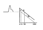
この出力信号は、A/Dコンバータに入力され、予めA/Dコンバータに設定されている、例えば図3に示すような線形の変換データ等に基づいて、上記信号出力期間11の信号レベルに対応するディジタル値を出力する。図3において、縦軸は撮像素子の出力信号レベルを示しており、横軸が変換されるディジタル値(輝度:1024階調)を示している。例えば、図3に示す変換データAによれば、図中の信号レベルは、ディジタル値X1に変換される。 This output signal is input to the A / D converter and corresponds to the signal level of the signal output period 11 based on, for example, linear conversion data as shown in FIG. The digital value to be output is output. In FIG. 3, the vertical axis indicates the output signal level of the image sensor, and the horizontal axis indicates the digital value (luminance: 1024 gradations) to be converted. For example, according to the conversion data A shown in FIG. 3, the signal level in the figure is converted into a digital value X1.
さて、上記第1の輝度補正手段2、及び第2の輝度補正手段3は、上記A/D変換処理の際に、A/Dコンバータに上記ディジタル値の補正を行わせる。
The first
第1の輝度補正手段2は、画像データの単位領域(本実施の形態では、線状に配置された撮像素子が一回に受光する反射光の領域、すなわち、1ラインが単位領域となる。)内の各画素のディジタル値を、この単位領域ごとに導出される量に応じてオフセットさせる(以下ではオートキャリブレーションという。)。例えば、このオートキャリブレーションは、画像データを取得の単位領域(1ライン)ごとに設けられている光学的黒画素の出力信号レベルを上記有効画素の出力信号レベルから差し引き、当該演算により得られる信号レベルに対して上記A/D変換処理を行う。 The first luminance correction means 2 is a unit area of image data (in this embodiment, an area of reflected light received by a linearly arranged image sensor at one time, that is, one line is a unit area. ) Are offset according to the amount derived for each unit area (hereinafter referred to as auto-calibration). For example, this auto-calibration is a signal obtained by subtracting the output signal level of the optical black pixel provided for each unit region (one line) for acquiring image data from the output signal level of the effective pixel. The A / D conversion process is performed on the level.
このように、有効画素の出力信号レベルから光学的黒画素の出力信号レベルを差し引くことで、光を受光していない光学的黒画素の出力信号レベルの変動(ノイズレベルの変動)を有効画素の出力信号レベルに反映させることができる。このため、光学的黒画素の出力信号レベルの変動と有効画素の出力信号レベルの変動とに相関がある場合には、有効画素の出力信号レベルからノイズレベルの変動分を除去することができ、画像データにより正確な輝度を与えることができる。 In this way, by subtracting the output signal level of the optical black pixel from the output signal level of the effective pixel, the fluctuation of the output signal level (noise level fluctuation) of the optical black pixel that does not receive the light can be reduced. It can be reflected in the output signal level. For this reason, when there is a correlation between the fluctuation of the output signal level of the optical black pixel and the fluctuation of the output signal level of the effective pixel, the fluctuation of the noise level can be removed from the output signal level of the effective pixel. Accurate luminance can be given by the image data.
例えば、上記撮像素子は、同一原稿上に存在する同一色かつ同一輝度である画像であっても、原稿上に大面積の白色領域が存在する場合、異なる信号レベルの信号を出力する場合がある(いわゆる、フレア現象。)。この白色領域の周辺に位置する部分の撮像素子の出力信号は、光学的黒画素の出力信号も含め、この白色領域の影響を受けて、図4に示すように、全体的に白色方向にシフト量Sだけシフトする。 For example, the image pickup device may output signals having different signal levels even when images having the same color and the same brightness are present on the same document and a large white area exists on the document. (The so-called flare phenomenon.) The output signal of the image sensor located in the periphery of the white area, including the output signal of the optical black pixel, is affected by the white area and is shifted in the overall white direction as shown in FIG. Shift by the amount S.
このため、このフレアの影響がある領域の撮像素子の出力信号からそのまま画像データが生成された場合、フレアの影響のない領域の出力信号から生成された画像データに比べて、画像データ出力部1a、1b、1cから出力されるディジタル値が大きな値になってしまう。 Therefore, when the image data is generated as it is from the output signal of the image sensor in the area affected by flare, the image data output unit 1a is compared with the image data generated from the output signal of the area not affected by flare. The digital values output from 1b and 1c become large values.
このような状況下で、上記オートキャリブレーションを適用すると、上記シフト量Sをキャンセルすることができ、フレアの影響を除去することができる。 Under such circumstances, when the auto calibration is applied, the shift amount S can be canceled and the influence of flare can be eliminated.
しかし、このオートキャリブレーションは、上述のように画像データの単位領域ごとに実行されるため、有効画素の出力信号レベルの変動と光学的黒画素の出力信号レベルの変動とに相関が無い場合は、画像データの輝度が不要に変化させられる(ノイズが付加される)ことになり、画像データの画質は全体的に劣化する。 However, since this auto-calibration is executed for each unit area of the image data as described above, when there is no correlation between the fluctuation of the output signal level of the effective pixel and the fluctuation of the output signal level of the optical black pixel. Therefore, the luminance of the image data is unnecessarily changed (noise is added), and the image quality of the image data is deteriorated as a whole.
一方、上記第2の輝度補正手段3は、上記A/Dコンバータの変換データ自体をオフセットさせる(以下、ソフトウェアオフセットという。)。このソフトウェアオフセットは、図3に示すように、A/Dコンバータの変換データを変換データAから変換データBにオフセット(オフセット値S0)させる。すなわち、変換データAによりディジタル値X1に変換されていた図中の信号レベルは、変換データBにより値X1よりも輝度の高い値X2に変換される。 On the other hand, the second luminance correction means 3 offsets the conversion data itself of the A / D converter (hereinafter referred to as software offset). This software offset causes the conversion data of the A / D converter to be offset from the conversion data A to the conversion data B (offset value S0) as shown in FIG. That is, the signal level in the figure that has been converted to the digital value X1 by the conversion data A is converted to a value X2 having a higher luminance than the value X1 by the conversion data B.
したがって、ソフトウェアオフセットは、予め設定したオフセット値は原稿の読み取り動作中に変化しないので、上記オートキャリブレーションのように特定の画素にノイズが付加されることがなく、有効画素の出力信号レベルをシフトさせることで画像データのS/N比を高めることができる。 Therefore, since the software offset does not change during the original reading operation, the preset offset value does not add noise to the specific pixel as in the above auto calibration, and the output signal level of the effective pixel is shifted. By doing so, the S / N ratio of the image data can be increased.
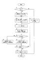
続いて、上記構成のスキャナ装置が行う処理を図5のフロー図に基づいて説明する。なお、上記第1の輝度補正手段2と第2の輝度補正手段3が輝度補正を行う画像データの色成分は、特に限定されるものではないが、本実施の形態では、図1に示すように、上記第1の輝度補正手段2が赤及び青画像データに補正の設定を行い、上記第2の輝度補正手段3が、緑画像データ出力部1bに補正の設定を行う構成としている。
Next, processing performed by the scanner apparatus having the above configuration will be described with reference to the flowchart of FIG. The color components of the image data for which the first
まず、ユーザがスキャン開始ボタンを押下する等により、カラースキャナ装置10に対して画像データの取得を指示すると、色種選択手段4がモノクロ画像データの取得が指示されているか否かを確認する(S1)。ここで、モノクロ画像データの取得が指示されている場合は(S1Yes)、色種選択手段4は、第1の輝度補正手段2、第2の輝度補正手段3、領域判別手段5、及び画像処理手段6にモノクロ画像データの取得を指示する。このとき、第1の輝度補正手段2は、緑成分出力部1bを上述のオートキャリブレーション設定状態にし(S2)、第2の輝度補正手段3は、赤及び青成分出力部1a,1cを上述のソフトウェアオフセット設定状態にする(S3)。
First, when the user instructs the
上記各輝度補正手段2、3の設定が完了すると、カラー画像読取手段1が原稿の読み取りを開始する。カラー画像読取手段1が1ラインの読み取りを完了すると、上記緑成分出力部1bから、オートキャリブレーションにより輝度補正された緑画像データが出力され、画像処理手段6に入力される。また、赤及び青成分出力部1a,1cから、ソフトウェアオフセットにより輝度補正された赤画像データと青画像データが出力され、領域判別手段5に入力される(S4)。
When the setting of each of the
領域判別手段5は、上記赤または青画像データに基づいて、例えば、隣接する画素の輝度変化量の大きさを検出することにより、変化の大きい領域を文字領域と判別し、変化の小さい領域を画像データとして判別する。ここで、赤(青)画像データは、上述のように、ソフトウェアオフセットにより補正が行われ、S/N比が良化された画像データであるため、より正確に文字領域と非文字領域との判別を行うことができる。
Based on the red or blue image data, the
このようにして、領域判別手段5が判別した領域種は、その位置情報とともに画像処理手段6に通知される。そして、画像処理手段6は、この領域種と位置情報とに基づいて、緑画像データの文字領域に、文字領域に適したガンマ補正(急峻な変化)等の文字領域用の画像処理を行い(S6Yes→S7)、緑画像データの非文字領域に、非文字領域に適したガンマ処理(なだらかな変化)等の非文字領域用の画像処理を行う(S6No→S8)。
Thus, the region type determined by the
この処理が原稿の読取が完了するまで繰り返され(S9No)、原稿の読取が完了したときに領域種に応じた画像処理が行われた緑画像データが画像処理手段6から、モノクロ画像データとして出力される(S9Yes→S10)。このとき、緑画像データは、フレアの影響を除去することができる輝度補正が行われているため、鮮明なモノクロ画像を得ることができる。 This process is repeated until the reading of the original is completed (No in S9), and when the original is read, the green image data subjected to image processing corresponding to the region type is output from the image processing means 6 as monochrome image data. (S9 Yes → S10). At this time, since the green image data has been subjected to luminance correction capable of removing the influence of flare, a clear monochrome image can be obtained.
以上、説明したように、本発明のカラースキャナ装置10によれば、モノクロ画像データを取得する際に、領域判別に適した補正処理を行った色成分の画像データを用いて領域判別を行い、他の色成分の画像データに対して領域判別手段が判別した領域種に応じた画像処理を行うので、文字領域と非文字領域とがともに鮮明なモノクロ画像データを取得することができる。また、上記他の色成分の画像データに、フレア等の影響を除去できる輝度補正を適用する構成とすれば、より鮮明な画像データを取得することができる。
As described above, according to the
また、上述のように、カラー画像読取手段1による原稿の読取と、上述の処理とは並行して行うことができるため、短時間でモノクロ画像データを取得することが可能であり、全画像データをメモリ等の記憶手段に格納する必要がなく、大容量のメモリも必要としない。
Further, as described above, since reading of a document by the color
一方、色種選択手段4がモノクロ画像データの取得が指示されているか否かを確認したときに、モノクロ画像データの取得が指示されていない場合は(S1No)、カラー画像データ出力処理として、任意の輝度補正が成された各色成分の画像データが画像処理手段6に入力され、画像処理手段6で適当な画像処理が行われた後、カラー画像データとして出力される(S11)。 On the other hand, when the color type selection unit 4 confirms whether acquisition of monochrome image data is instructed or not, if acquisition of monochrome image data is not instructed (No in S1), an arbitrary color image data output process is performed. The image data of each color component subjected to the luminance correction is input to the image processing means 6, and after appropriate image processing is performed by the image processing means 6, it is output as color image data (S11).
なお、図1の例では、カラースキャナ装置10の外部に画像データを出力する構成としているが、当該カラースキャナ装置10に記憶手段を備え、当該記憶手段に画像データを記憶する構成としても良い。
In the example of FIG. 1, the image data is output to the outside of the
また、上記説明では、第1の輝度補正手段2を緑画像データ出力部1bに適用したが、第1の輝度補正手段2を適用した画像データ出力部の画像データが領域判別手段5に入力される構成であれば、第1の輝度補正手段2を適用する色成分は任意であり、第2の輝度補正手段3は、第1の輝度補正手段2を適用した色成分以外の色成分に適用すればよい。
In the above description, the first
さらに、本実施の形態では、カラー画像データとして、RGBの画像データを取得する構成としたが、カラー画像データを構成可能な色成分の組み合わせであれば、その色種も数も任意に選択することが可能である。 Furthermore, in the present embodiment, RGB image data is acquired as color image data. However, any combination of color components and number can be selected as long as the color component can be combined with color image data. It is possible.
加えて、本発明はカラースキャナ装置単体に限らず、画像読取機能を有する複写機や複合機等の画像形成装置に適用できることは言うまでもない。 In addition, it goes without saying that the present invention is not limited to a single color scanner device but can be applied to an image forming apparatus such as a copying machine or a multifunction machine having an image reading function.
本発明は、鮮明なモノクロ画像を取得できるという効果を有し、カラー複写機等の画像形成装置に搭載可能なカラースキャナ装置として有用である。 The present invention has an effect that a clear monochrome image can be obtained, and is useful as a color scanner device that can be mounted on an image forming apparatus such as a color copying machine.
1 カラー画像読取手段
2 第1の輝度補正手段
3 第2の輝度補正手段
4 色種選択手段
5 領域判別手段
6 画像処理手段
10 カラースキャナ裝置
S フレア現象による輝度のシフト量
DESCRIPTION OF
Claims (3)
前記色種選択手段がモノクロ画像データ取得を選択しているときに、
少なくとも1つの前記色成分の画像データに対して、各画素の輝度を予め設定した所定量だけオフセットさせる輝度補正を行う第1の輝度補正手段と、
前記第1の輝度補正手段が輝度補正を行った画像データに基づいて、前記領域判別を行う前記領域判別手段と、
少なくとも1つの他の色成分の画像データに対して、前記領域判別手段が判別した領域種に応じた画像処理を行い、前記モノクロ画像データとして出力する画像処理手段と、
を備えることを特徴とするカラースキャナ装置。 Color image reading means for optically reading a document for each unit area and acquiring image data separated into a plurality of color components, and distinguishing between a character area and a non-character area based on a luminance change of a pixel in the image data In a color scanner device comprising: a region discriminating unit for performing; and a color type selecting unit for selecting whether the original is acquired as color image data or monochrome image data.
When the color type selection means has selected monochrome image data acquisition,
First luminance correction means for performing luminance correction for offsetting the luminance of each pixel by a predetermined amount with respect to image data of at least one color component;
The area determination means for determining the area based on the image data on which the first brightness correction means has performed the brightness correction;
Image processing means for performing image processing according to the area type determined by the area determination means for image data of at least one other color component, and outputting the monochrome image data;
A color scanner device comprising:
前記画像処理手段が、前記第2の輝度補正手段が輝度補正を行った画像データに対して、前記領域判別手段が判別した領域種に応じた画像処理を行い、前記モノクロ画像データとして出力する請求項1に記載のカラースキャナ装置。 Second luminance correction means for performing luminance correction for offsetting the luminance of each pixel in each unit region by an amount derived for each unit region with respect to the image data of the other color component;
The image processing means performs image processing according to the area type determined by the area determination means on the image data subjected to the brightness correction by the second brightness correction means, and outputs the image data as the monochrome image data. Item 2. The color scanner device according to Item 1.
Priority Applications (1)
| Application Number | Priority Date | Filing Date | Title |
|---|---|---|---|
| JP2004109408A JP2005295345A (en) | 2004-04-01 | 2004-04-01 | Color scanner device |
Applications Claiming Priority (1)
| Application Number | Priority Date | Filing Date | Title |
|---|---|---|---|
| JP2004109408A JP2005295345A (en) | 2004-04-01 | 2004-04-01 | Color scanner device |
Publications (1)
| Publication Number | Publication Date |
|---|---|
| JP2005295345A true JP2005295345A (en) | 2005-10-20 |
Family
ID=35327766
Family Applications (1)
| Application Number | Title | Priority Date | Filing Date |
|---|---|---|---|
| JP2004109408A Pending JP2005295345A (en) | 2004-04-01 | 2004-04-01 | Color scanner device |
Country Status (1)
| Country | Link |
|---|---|
| JP (1) | JP2005295345A (en) |
-
2004
- 2004-04-01 JP JP2004109408A patent/JP2005295345A/en active Pending
Similar Documents
| Publication | Publication Date | Title |
|---|---|---|
| JP4668185B2 (en) | Image processing method | |
| US5189523A (en) | Image processing apparatus | |
| JPH05137000A (en) | Image reader | |
| JP2001307079A (en) | Image processing apparatus, image processing method, and recording medium | |
| EP2439922A1 (en) | Image processing apparatus, method for processing image, and program therefor | |
| US6175660B1 (en) | Image reading apparatus | |
| US20080187243A1 (en) | Image reading apparatus and image reading method | |
| JP4871665B2 (en) | Image input apparatus and image forming apparatus | |
| JPH05316377A (en) | Picture processing unit | |
| JP2006260526A (en) | Image processing apparatus and image processing method | |
| JP2005295345A (en) | Color scanner device | |
| JP4003439B2 (en) | Image forming apparatus and image forming method | |
| JP3226224B2 (en) | Image processing device | |
| JP4314141B2 (en) | Document image identification device, color copying machine, and document image identification method | |
| JP2000232618A (en) | Photo-finishing method, system therefor and recording medium | |
| JPH03201772A (en) | Image scanner | |
| JP5074795B2 (en) | Imaging apparatus, video signal correction method, program, and storage medium | |
| JP3206932B2 (en) | Image processing method and apparatus | |
| KR100264336B1 (en) | All applicable scanner for pixel unit color scanning method and line unit scannong method | |
| JP2007060049A (en) | Image reading apparatus | |
| JP2011055362A (en) | Image reading apparatus | |
| JP2004147347A (en) | Index print creation method | |
| JP2004128839A (en) | Image processing device | |
| JPH0449773A (en) | Color reading device | |
| JPH08251385A (en) | Image processing device |