JP2005295225A - Baseband signal generating device, and baseband signal generating method and program - Google Patents
Baseband signal generating device, and baseband signal generating method and program Download PDFInfo
- Publication number
- JP2005295225A JP2005295225A JP2004107774A JP2004107774A JP2005295225A JP 2005295225 A JP2005295225 A JP 2005295225A JP 2004107774 A JP2004107774 A JP 2004107774A JP 2004107774 A JP2004107774 A JP 2004107774A JP 2005295225 A JP2005295225 A JP 2005295225A
- Authority
- JP
- Japan
- Prior art keywords
- baseband signal
- data
- communication quality
- symbols
- value
- Prior art date
- Legal status (The legal status is an assumption and is not a legal conclusion. Google has not performed a legal analysis and makes no representation as to the accuracy of the status listed.)
- Granted
Links
- 238000000034 method Methods 0.000 title claims description 49
- 238000004891 communication Methods 0.000 claims abstract description 140
- 230000005540 biological transmission Effects 0.000 claims abstract description 113
- 230000007274 generation of a signal involved in cell-cell signaling Effects 0.000 claims description 87
- 238000001514 detection method Methods 0.000 claims description 28
- 238000012545 processing Methods 0.000 abstract description 39
- 230000008569 process Effects 0.000 description 24
- 230000006870 function Effects 0.000 description 15
- 230000005236 sound signal Effects 0.000 description 7
- 230000015654 memory Effects 0.000 description 5
- 238000006243 chemical reaction Methods 0.000 description 4
- 238000012937 correction Methods 0.000 description 4
- 238000010586 diagram Methods 0.000 description 4
- 230000000873 masking effect Effects 0.000 description 3
- 230000001174 ascending effect Effects 0.000 description 2
- 238000005259 measurement Methods 0.000 description 2
- 230000008859 change Effects 0.000 description 1
- 230000008878 coupling Effects 0.000 description 1
- 238000010168 coupling process Methods 0.000 description 1
- 238000005859 coupling reaction Methods 0.000 description 1
- 238000005562 fading Methods 0.000 description 1
- 239000003550 marker Substances 0.000 description 1
- 230000007246 mechanism Effects 0.000 description 1
- 230000010355 oscillation Effects 0.000 description 1
- 230000010363 phase shift Effects 0.000 description 1
- 238000005070 sampling Methods 0.000 description 1
Images


Classifications
-
- H—ELECTRICITY
- H04—ELECTRIC COMMUNICATION TECHNIQUE
- H04L—TRANSMISSION OF DIGITAL INFORMATION, e.g. TELEGRAPHIC COMMUNICATION
- H04L1/00—Arrangements for detecting or preventing errors in the information received
- H04L1/0001—Systems modifying transmission characteristics according to link quality, e.g. power backoff
- H04L1/0002—Systems modifying transmission characteristics according to link quality, e.g. power backoff by adapting the transmission rate
- H04L1/0003—Systems modifying transmission characteristics according to link quality, e.g. power backoff by adapting the transmission rate by switching between different modulation schemes
-
- H—ELECTRICITY
- H03—ELECTRONIC CIRCUITRY
- H03M—CODING; DECODING; CODE CONVERSION IN GENERAL
- H03M13/00—Coding, decoding or code conversion, for error detection or error correction; Coding theory basic assumptions; Coding bounds; Error probability evaluation methods; Channel models; Simulation or testing of codes
- H03M13/35—Unequal or adaptive error protection, e.g. by providing a different level of protection according to significance of source information or by adapting the coding according to the change of transmission channel characteristics
-
- H—ELECTRICITY
- H04—ELECTRIC COMMUNICATION TECHNIQUE
- H04L—TRANSMISSION OF DIGITAL INFORMATION, e.g. TELEGRAPHIC COMMUNICATION
- H04L1/00—Arrangements for detecting or preventing errors in the information received
- H04L1/004—Arrangements for detecting or preventing errors in the information received by using forward error control
- H04L1/0056—Systems characterized by the type of code used
- H04L1/007—Unequal error protection
-
- H—ELECTRICITY
- H04—ELECTRIC COMMUNICATION TECHNIQUE
- H04L—TRANSMISSION OF DIGITAL INFORMATION, e.g. TELEGRAPHIC COMMUNICATION
- H04L27/00—Modulated-carrier systems
- H04L27/10—Frequency-modulated carrier systems, i.e. using frequency-shift keying
- H04L27/14—Demodulator circuits; Receiver circuits
Landscapes
- Engineering & Computer Science (AREA)
- Computer Networks & Wireless Communication (AREA)
- Signal Processing (AREA)
- Physics & Mathematics (AREA)
- Probability & Statistics with Applications (AREA)
- Theoretical Computer Science (AREA)
- Quality & Reliability (AREA)
- Detection And Prevention Of Errors In Transmission (AREA)
- Error Detection And Correction (AREA)
- Dc Digital Transmission (AREA)
Abstract
Description
本発明は、ベースバンド信号生成装置、ベースバンド信号生成方法及びプログラムに関する。 The present invention relates to a baseband signal generation device, a baseband signal generation method, and a program.
伝送路の通信品質に応じた最適な効率でデータを伝送するための技術として、伝送路の通信品質が悪い場合はビットレートを低くし、良い場合はビットレートを高くする、という手法が用いられている。 As a technique for transmitting data with the optimum efficiency according to the communication quality of the transmission path, a technique of lowering the bit rate when the communication quality of the transmission path is poor and increasing the bit rate when it is good is used. ing.
この手法は、具体的には、例えば、パケット通信において、通信品質が所定の基準を満たさない場合は伝送する対象のデータにFEC(Forward Error Correction:前方向誤り訂正)を施すことによって実質上ビットレートを低くし、通信品質がこの基準を満たす場合は、FECを施さないようにすることで実質上ビットレートを高くする、というものである(例えば、非特許文献1の第1分冊p.160−161参照)。
しかし、データにFECを施すと、このデータを構成するビット列内のビットの配置は大きく変化する。従って、データを受信して復元する側の装置は、データにFECが施されているか否かを知る必要があり、このため、FECの利用の有無を示すデータを、伝送効率の悪化を招く複雑なプロトコルに従って、別途伝送する必要があった。 However, when FEC is applied to the data, the arrangement of bits in the bit string constituting the data changes greatly. Therefore, the device that receives and restores the data needs to know whether or not the data is subjected to FEC. For this reason, the data indicating the presence or absence of the use of FEC is complicated to cause the transmission efficiency to deteriorate. It was necessary to transmit separately according to a different protocol.
本発明は、このような従来の問題点に鑑みてなされたもので、伝送対象のデータに処理が施されているか否かを認識することなく受信側が当該データを復元できるように当該データを処理し、通信品質に応じた適正な効率で当該データを伝送するためのベースバンド信号生成装置、ベースバンド信号生成方法及びプログラムを提供することを目的とする。 The present invention has been made in view of such conventional problems, and processes the data so that the receiving side can restore the data without recognizing whether or not the data to be transmitted has been processed. It is an object of the present invention to provide a baseband signal generation device, a baseband signal generation method, and a program for transmitting the data with appropriate efficiency according to communication quality.
この目的を達成するため、本発明の第1の観点に係るベースバンド信号生成装置は、
データを、4値のシンボルの列を表すベースバンド信号へと変換するベースバンド信号生成手段と、
前記ベースバンド信号を伝送する外部の伝送路の通信品質が所定の基準に達しているか否かを判定する通信品質判定手段と、より構成され、
前記データを構成するビット列の少なくとも一部は、保護対象部分として区別されており、
前記ベースバンド信号生成手段は、
前記伝送路の通信品質が前記基準に達していないと判定されている状態においては、前記シンボルの列に属する少なくとも一部のシンボルが、前記保護対象部分に属するビット、及び所定の冗長ビットを含むように、前記データを前記ベースバンド信号へと変換し、
前記伝送路の通信品質が前記基準に達していると判定されている状態においては、前記シンボルの列に属する少なくとも一部のシンボルが、前記保護対象部分に属するビット、及び、前記データと共に前記ベースバンド信号へと変換する追加データを含むように、前記データを前記ベースバンド信号へと変換するものであり、
前記冗長ビットの値は、前記ベースバンド信号内の、当該冗長ビットを含んでいるシンボルを表す点の瞬時値が、当該瞬時値が収束し得る4値のうちの最大値又は最小値へと常に収束することとなるような値である、
ことを特徴とする。
In order to achieve this object, a baseband signal generation device according to the first aspect of the present invention provides:
Baseband signal generating means for converting data into a baseband signal representing a sequence of four-valued symbols;
Communication quality determining means for determining whether or not the communication quality of the external transmission path for transmitting the baseband signal has reached a predetermined standard, and
At least a part of the bit string constituting the data is distinguished as a protection target part,
The baseband signal generation means includes
In a state where it is determined that the communication quality of the transmission path does not reach the reference, at least some symbols belonging to the symbol sequence include bits belonging to the protection target portion and predetermined redundant bits. Converting the data into the baseband signal,
In a state in which it is determined that the communication quality of the transmission path has reached the reference, at least a part of the symbols belonging to the symbol sequence includes the base and the bits belonging to the protection target portion and the data. Converting the data into the baseband signal to include additional data to be converted into a band signal;
The value of the redundant bit is always the maximum value or the minimum value of the four values that can be converged by the instantaneous value of the point representing the symbol including the redundant bit in the baseband signal. A value that will converge,
It is characterized by that.
また、本発明の第2の観点に係るベースバンド信号生成装置は、
データを、多値のシンボルの列を表すベースバンド信号へと変換するベースバンド信号生成手段と、
前記ベースバンド信号を伝送する外部の伝送路の通信品質が所定の基準に達しているか否かを判定する通信品質判定手段と、より構成され、
前記データを構成するビット列の少なくとも一部は、保護対象部分として区別されており、
前記ベースバンド信号生成手段は、
前記伝送路の通信品質が前記基準に達していないと判定されている状態においては、前記シンボルの列に属する少なくとも一部のシンボルが、前記保護対象部分に属するビット、及び所定の冗長ビットを含むように、前記データを前記ベースバンド信号へと変換し、
前記伝送路の通信品質が前記基準に達していると判定されている状態においては、前記シンボルの列に属する少なくとも一部のシンボルが、前記保護対象部分に属するビット、及び、前記データと共に前記ベースバンド信号へと変換する追加データを含むように、前記データを前記ベースバンド信号へと変換するものであり、
前記冗長ビットの値は、前記ベースバンド信号内の、当該冗長ビットを含んでいて値が互いに異なる2個のシンボルを表す2個の点の瞬時値の差の最小値が、当該冗長ビットを含まない互いに異なる2個のシンボルを表す2個の点の瞬時値の差の最小値より大きくなるような値である、
ことを特徴とする。
A baseband signal generation device according to the second aspect of the present invention provides:
Baseband signal generation means for converting data into a baseband signal representing a sequence of multi-valued symbols;
Communication quality determining means for determining whether or not the communication quality of the external transmission path for transmitting the baseband signal has reached a predetermined standard, and
At least a part of the bit string constituting the data is distinguished as a protection target part,
The baseband signal generation means includes
In a state where it is determined that the communication quality of the transmission path does not reach the reference, at least some symbols belonging to the symbol sequence include bits belonging to the protection target portion and predetermined redundant bits. Converting the data into the baseband signal,
In a state in which it is determined that the communication quality of the transmission path has reached the reference, at least a part of the symbols belonging to the symbol sequence includes the base and the bits belonging to the protection target portion and the data. Converting the data into the baseband signal to include additional data to be converted into a band signal;
The value of the redundant bit is the minimum value of the difference between the instantaneous values of two points representing the two symbols having the redundant bit and different values in the baseband signal. A value that is greater than the minimum difference between the instantaneous values of two points that represent two different symbols
It is characterized by that.
また、本発明の第3の観点に係るベースバンド信号生成装置は、
データを、多値のシンボルの列を表すベースバンド信号へと変換するベースバンド信号生成手段と、
前記ベースバンド信号を伝送する外部の伝送路の通信品質を判定する通信品質判定手段と、より構成され、
前記データを構成するビット列の少なくとも一部は、保護対象部分として区別されており、
前記ベースバンド信号生成手段は、前記シンボルの列に属する少なくとも一部のシンボルが、前記保護対象部分に属するビットと、所定の冗長ビット若しくは前記データと共に前記ベースバンド信号へと変換する追加データと、を含み、且つ、前記伝送路の通信品質が良好であるほど、前記追加データを含むシンボルが多くなるように、前記データを前記ベースバンド信号へと変換するものであって、
前記冗長ビットの値は、前記ベースバンド信号内の、当該冗長ビットを含んでいて値が互いに異なる2個のシンボルを表す2個の点の瞬時値の差の最小値が、当該冗長ビットを含まない互いに異なる2個のシンボルを表す2個の点の瞬時値の差の最小値より大きくなるような値である、
ことを特徴とする。
In addition, a baseband signal generation device according to the third aspect of the present invention provides:
Baseband signal generation means for converting data into a baseband signal representing a sequence of multi-valued symbols;
Communication quality determination means for determining communication quality of an external transmission path for transmitting the baseband signal, and
At least a part of the bit string constituting the data is distinguished as a protection target part,
The baseband signal generation means includes at least a part of symbols belonging to the symbol sequence, bits belonging to the protection target portion, and additional data to be converted into the baseband signal together with predetermined redundant bits or the data; And the data is converted into the baseband signal such that the better the communication quality of the transmission path, the more symbols including the additional data,
The value of the redundant bit is the minimum value of the difference between the instantaneous values of two points representing the two symbols having the redundant bit and different values in the baseband signal. A value that is greater than the minimum difference between the instantaneous values of two points that represent two different symbols
It is characterized by that.
前記データは、当該データが表す対象が含み得る成分に対応付けられたビットより構成されており、当該ビットは、当該ビットに対応付けられた成分が前記対象内に存在しないことを示すとき、前記冗長ビットの値と同一の値をとるものであるものであってもよい。 The data is composed of bits associated with components that can be included in the object represented by the data, and the bits indicate that the component associated with the bit does not exist in the object, It may be the same value as the value of the redundant bit.
前記ベースバンド信号生成手段は、前記ベースバンド信号が表す前記シンボルの列が、前記冗長ビット又は前記追加データを含むシンボルと前記冗長ビット及び前記追加データを含まないシンボルとを交互に並べた部分を含むものとなるように、前記データを前記ベースバンド信号へと変換するものであってもよい。 The baseband signal generation means includes a portion in which the symbol sequence represented by the baseband signal is an alternating arrangement of symbols including the redundant bits or the additional data and symbols not including the redundant bits and the additional data. The data may be converted into the baseband signal so as to be included.
前記データは、音声を符号化することにより得られるビット列の一部を含んでおり、前記追加データは、当該ビット列の他の一部を含んでいるものであってもよい。 The data may include a part of a bit string obtained by encoding speech, and the additional data may include another part of the bit string.
前記データは、ビット列のうち、所定の基準に基づいて決まる重要度が最も高い部分を含んでおり、前記追加データは、当該ビット列のうち、前記重要度が最も低い部分を含んでいてもよい。 The data may include a portion having the highest importance determined based on a predetermined criterion in the bit string, and the additional data may include a portion having the lowest importance in the bit string.
前記通信品質判定手段は、
前記伝送路上で伝送されている信号の強度を測定する手段と、
測定された前記信号の強度に基づいて、前記伝送路の通信品質を判定する手段と、を備えるものであってもよい。
The communication quality determination means includes
Means for measuring the intensity of a signal being transmitted on the transmission path;
Means for determining the communication quality of the transmission path based on the measured signal strength.
前記データの少なくとも一部は、保護対象部分の誤り検出用のデータを含んでいてもよく、
前記ベースバンド信号生成手段は、前記伝送路の通信品質の判定結果に係らず、前記シンボルの列に属する少なくとも一部のシンボルが、前記誤り検出用のデータを構成するビット、及び前記冗長ビットを含むように、前記データを前記ベースバンド信号へと変換するものであってもよい。
At least a part of the data may include error detection data of the protection target part,
The baseband signal generation means includes at least a part of the symbols belonging to the symbol sequence, the bits constituting the error detection data, and the redundant bits regardless of the determination result of the communication quality of the transmission path. In other words, the data may be converted into the baseband signal.
前記ベースバンド信号生成装置は、前記ベースバンド信号生成手段が生成した前記ベースバンド信号を用いて変調波を生成し、当該変調波を前記伝送路に送出する変調手段を更に備えるものであってもよい。 The baseband signal generation device may further include a modulation unit that generates a modulated wave using the baseband signal generated by the baseband signal generation unit and sends the modulated wave to the transmission path. Good.
また、本発明の第4の観点に係るベースバンド信号生成方法は、
データを、4値のシンボルの列を表すベースバンド信号へと変換するベースバンド信号生成ステップと、
前記ベースバンド信号を伝送する外部の伝送路の通信品質が所定の基準に達しているか否かを判定する通信品質判定ステップと、より構成され、
前記データを構成するビット列の少なくとも一部は、保護対象部分として区別されており、
前記ベースバンド信号生成ステップは、
前記伝送路の通信品質が前記基準に達していないと判定されている状態においては、前記シンボルの列に属する少なくとも一部のシンボルが、前記保護対象部分に属するビット、及び所定の冗長ビットを含むように、前記データを前記ベースバンド信号へと変換し、
前記伝送路の通信品質が前記基準に達していると判定されている状態においては、前記シンボルの列に属する少なくとも一部のシンボルが、前記保護対象部分に属するビット、及び、前記データと共に前記ベースバンド信号へと変換する追加データを含むように、前記データを前記ベースバンド信号へと変換するステップであり、
前記冗長ビットの値は、前記ベースバンド信号内の、当該冗長ビットを含んでいるシンボルを表す点の瞬時値が、当該瞬時値が収束し得る4値のうちの最大値又は最小値へと常に収束することとなるような値である、
ことを特徴とする。
A baseband signal generation method according to the fourth aspect of the present invention includes:
A baseband signal generation step of converting the data into a baseband signal representing a sequence of quaternary symbols;
A communication quality determination step for determining whether or not the communication quality of an external transmission path for transmitting the baseband signal has reached a predetermined standard, and
At least a part of the bit string constituting the data is distinguished as a protection target part,
The baseband signal generation step includes:
In a state where it is determined that the communication quality of the transmission path does not reach the reference, at least some symbols belonging to the symbol sequence include bits belonging to the protection target portion and predetermined redundant bits. Converting the data into the baseband signal,
In a state in which it is determined that the communication quality of the transmission path has reached the reference, at least a part of the symbols belonging to the symbol sequence includes the base and the bits belonging to the protection target portion and the data. Converting the data into the baseband signal to include additional data to convert into a band signal;
The value of the redundant bit is always the maximum value or the minimum value of the four values that can be converged by the instantaneous value of the point representing the symbol including the redundant bit in the baseband signal. A value that will converge,
It is characterized by that.
また、本発明の第5の観点に係るベースバンド信号生成方法は、
データを、多値のシンボルの列を表すベースバンド信号へと変換するベースバンド信号生成ステップと、
前記ベースバンド信号を伝送する外部の伝送路の通信品質が所定の基準に達しているか否かを判定する通信品質判定ステップと、より構成され、
前記データを構成するビット列の少なくとも一部は、保護対象部分として区別されており、
前記ベースバンド信号生成ステップは、
前記伝送路の通信品質が前記基準に達していないと判定されている状態においては、前記シンボルの列に属する少なくとも一部のシンボルが、前記保護対象部分に属するビット、及び所定の冗長ビットを含むように、前記データを前記ベースバンド信号へと変換し、
前記伝送路の通信品質が前記基準に達していると判定されている状態においては、前記シンボルの列に属する少なくとも一部のシンボルが、前記保護対象部分に属するビット、及び、前記データと共に前記ベースバンド信号へと変換する追加データを含むように、前記データを前記ベースバンド信号へと変換するステップであり、
前記冗長ビットの値は、前記ベースバンド信号内の、当該冗長ビットを含んでいて値が互いに異なる2個のシンボルを表す2個の点の瞬時値の差の最小値が、当該冗長ビットを含まない互いに異なる2個のシンボルを表す2個の点の瞬時値の差の最小値より大きくなるような値である、
ことを特徴とする。
A baseband signal generation method according to the fifth aspect of the present invention includes:
A baseband signal generation step for converting the data into a baseband signal representing a sequence of multi-valued symbols;
A communication quality determination step for determining whether or not the communication quality of an external transmission path for transmitting the baseband signal has reached a predetermined standard, and
At least a part of the bit string constituting the data is distinguished as a protection target part,
The baseband signal generation step includes:
In a state where it is determined that the communication quality of the transmission path does not reach the reference, at least some symbols belonging to the symbol sequence include bits belonging to the protection target portion and predetermined redundant bits. Converting the data into the baseband signal,
In a state in which it is determined that the communication quality of the transmission path has reached the reference, at least a part of the symbols belonging to the symbol sequence includes the base and the bits belonging to the protection target portion and the data. Converting the data into the baseband signal to include additional data to convert into a band signal;
The value of the redundant bit is the minimum value of the difference between the instantaneous values of two points representing the two symbols having the redundant bit and different values in the baseband signal. A value that is greater than the minimum difference between the instantaneous values of two points that represent two different symbols
It is characterized by that.
また、本発明の第6の観点に係るベースバンド信号生成方法は、
データを、多値のシンボルの列を表すベースバンド信号へと変換するベースバンド信号生成ステップと、
前記ベースバンド信号を伝送する外部の伝送路の通信品質を判定する通信品質判定ステップと、より構成され、
前記データを構成するビット列の少なくとも一部は、保護対象部分として区別されており、
前記ベースバンド信号生成ステップは、前記シンボルの列に属する少なくとも一部のシンボルが、前記保護対象部分に属するビットと、所定の冗長ビット若しくは前記データと共に前記ベースバンド信号へと変換する追加データと、を含み、且つ、前記伝送路の通信品質が良好であるほど、前記追加データを含むシンボルが多くなるように、前記データを前記ベースバンド信号へと変換するステップであって、
前記冗長ビットの値は、前記ベースバンド信号内の、当該冗長ビットを含んでいて値が互いに異なる2個のシンボルを表す2個の点の瞬時値の差の最小値が、当該冗長ビットを含まない互いに異なる2個のシンボルを表す2個の点の瞬時値の差の最小値より大きくなるような値である、
ことを特徴とする。
A baseband signal generation method according to the sixth aspect of the present invention includes:
A baseband signal generation step for converting the data into a baseband signal representing a sequence of multi-valued symbols;
A communication quality determination step for determining communication quality of an external transmission path for transmitting the baseband signal, and
At least a part of the bit string constituting the data is distinguished as a protection target part,
In the baseband signal generation step, at least some symbols belonging to the symbol sequence include bits belonging to the protection target portion, predetermined redundant bits or additional data to be converted into the baseband signal together with the data, And converting the data into the baseband signal such that the better the communication quality of the transmission path, the greater the number of symbols including the additional data,
The value of the redundant bit is the minimum value of the difference between the instantaneous values of two points representing the two symbols having the redundant bit and different values in the baseband signal. A value that is greater than the minimum difference between the instantaneous values of two points that represent two different symbols
It is characterized by that.
また、本発明の第7の観点に係るプログラムは、
コンピュータを、
データを、4値のシンボルの列を表すベースバンド信号へと変換するベースバンド信号生成手段と、
前記ベースバンド信号を伝送する外部の伝送路の通信品質が所定の基準に達しているか否かを判定する通信品質判定手段と、して機能させるためのプログラムであって、
前記データを構成するビット列の少なくとも一部は、保護対象部分として区別されており、
前記ベースバンド信号生成手段は、
前記伝送路の通信品質が前記基準に達していないと判定されている状態においては、前記シンボルの列に属する少なくとも一部のシンボルが、前記保護対象部分に属するビット、及び所定の冗長ビットを含むように、前記データを前記ベースバンド信号へと変換し、
前記伝送路の通信品質が前記基準に達していると判定されている状態においては、前記シンボルの列に属する少なくとも一部のシンボルが、前記保護対象部分に属するビット、及び、前記データと共に前記ベースバンド信号へと変換する追加データを含むように、前記データを前記ベースバンド信号へと変換するものであり、
前記冗長ビットの値は、前記ベースバンド信号内の、当該冗長ビットを含んでいるシンボルを表す点の瞬時値が、当該瞬時値が収束し得る4値のうちの最大値又は最小値へと常に収束することとなるような値である、
ことを特徴とする。
A program according to the seventh aspect of the present invention is
Computer
Baseband signal generating means for converting data into a baseband signal representing a sequence of four-valued symbols;
A program for functioning as communication quality determination means for determining whether communication quality of an external transmission path for transmitting the baseband signal has reached a predetermined standard,
At least a part of the bit string constituting the data is distinguished as a protection target part,
The baseband signal generation means includes
In a state where it is determined that the communication quality of the transmission path does not reach the reference, at least some symbols belonging to the symbol sequence include bits belonging to the protection target portion and predetermined redundant bits. Converting the data into the baseband signal,
In a state in which it is determined that the communication quality of the transmission path has reached the reference, at least a part of the symbols belonging to the symbol sequence includes the base and the bits belonging to the protection target portion and the data. Converting the data into the baseband signal to include additional data to be converted into a band signal;
The value of the redundant bit is always the maximum value or the minimum value of the four values that can be converged by the instantaneous value of the point representing the symbol including the redundant bit in the baseband signal. A value that will converge,
It is characterized by that.
また、本発明の第8の観点に係るプログラムは、
コンピュータを、
データを、多値のシンボルの列を表すベースバンド信号へと変換するベースバンド信号生成手段と、
前記ベースバンド信号を伝送する外部の伝送路の通信品質が所定の基準に達しているか否かを判定する通信品質判定手段と、して機能させるためのプログラムであって、
前記データを構成するビット列の少なくとも一部は、保護対象部分として区別されており、
前記ベースバンド信号生成手段は、
前記伝送路の通信品質が前記基準に達していないと判定されている状態においては、前記シンボルの列に属する少なくとも一部のシンボルが、前記保護対象部分に属するビット、及び所定の冗長ビットを含むように、前記データを前記ベースバンド信号へと変換し、
前記伝送路の通信品質が前記基準に達していると判定されている状態においては、前記シンボルの列に属する少なくとも一部のシンボルが、前記保護対象部分に属するビット、及び、前記データと共に前記ベースバンド信号へと変換する追加データを含むように、前記データを前記ベースバンド信号へと変換するものであり、
前記冗長ビットの値は、前記ベースバンド信号内の、当該冗長ビットを含んでいて値が互いに異なる2個のシンボルを表す2個の点の瞬時値の差の最小値が、当該冗長ビットを含まない互いに異なる2個のシンボルを表す2個の点の瞬時値の差の最小値より大きくなるような値である、
ことを特徴とする。
A program according to the eighth aspect of the present invention is:
Computer
Baseband signal generation means for converting data into a baseband signal representing a sequence of multi-valued symbols;
A program for functioning as communication quality determination means for determining whether communication quality of an external transmission path for transmitting the baseband signal has reached a predetermined standard,
At least a part of the bit string constituting the data is distinguished as a protection target part,
The baseband signal generation means includes
In a state where it is determined that the communication quality of the transmission path does not reach the reference, at least some symbols belonging to the symbol sequence include bits belonging to the protection target portion and predetermined redundant bits. Converting the data into the baseband signal,
In a state in which it is determined that the communication quality of the transmission path has reached the reference, at least a part of the symbols belonging to the symbol sequence includes the base and the bits belonging to the protection target portion and the data. Converting the data into the baseband signal to include additional data to be converted into a band signal;
The value of the redundant bit is the minimum value of the difference between the instantaneous values of two points representing the two symbols having the redundant bit and different values in the baseband signal. A value that is greater than the minimum difference between the instantaneous values of two points that represent two different symbols
It is characterized by that.
また、本発明の第9の観点に係るプログラムは、
コンピュータを、
データを、多値のシンボルの列を表すベースバンド信号へと変換するベースバンド信号生成手段と、
前記ベースバンド信号を伝送する外部の伝送路の通信品質を判定する通信品質判定手段と、して機能させるためのプログラムであって、
前記データを構成するビット列の少なくとも一部は、保護対象部分として区別されており、
前記ベースバンド信号生成手段は、前記シンボルの列に属する少なくとも一部のシンボルが、前記保護対象部分に属するビットと、所定の冗長ビット若しくは前記データと共に前記ベースバンド信号へと変換する追加データと、を含み、且つ、前記伝送路の通信品質が良好であるほど、前記追加データを含むシンボルが多くなるように、前記データを前記ベースバンド信号へと変換するものであって、
前記冗長ビットの値は、前記ベースバンド信号内の、当該冗長ビットを含んでいて値が互いに異なる2個のシンボルを表す2個の点の瞬時値の差の最小値が、当該冗長ビットを含まない互いに異なる2個のシンボルを表す2個の点の瞬時値の差の最小値より大きくなるような値である、
ことを特徴とする。
A program according to the ninth aspect of the present invention is
Computer
Baseband signal generation means for converting data into a baseband signal representing a sequence of multi-valued symbols;
A program for functioning as communication quality determination means for determining communication quality of an external transmission path for transmitting the baseband signal,
At least a part of the bit string constituting the data is distinguished as a protection target part,
The baseband signal generation means includes at least a part of symbols belonging to the symbol sequence, bits belonging to the protection target portion, and additional data to be converted into the baseband signal together with predetermined redundant bits or the data; And the data is converted into the baseband signal such that the better the communication quality of the transmission path, the more symbols including the additional data,
The value of the redundant bit is the minimum value of the difference between the instantaneous values of two points representing the two symbols having the redundant bit and different values in the baseband signal. A value that is greater than the minimum difference between the instantaneous values of two points that represent two different symbols
It is characterized by that.
本発明によれば、伝送対象のデータに処理が施されているか否かを認識することなく受信側が当該データを復元できるように当該データを処理し、通信品質に応じた適正な効率で当該データを伝送するためのベースバンド信号生成装置、ベースバンド信号生成方法及びプログラムが実現される。 According to the present invention, the data is processed so that the receiving side can restore the data without recognizing whether or not the data to be transmitted is processed, and the data is processed with appropriate efficiency according to the communication quality. A baseband signal generation device, a baseband signal generation method, and a program for transmitting a signal are realized.
以下、本発明の実施の形態を、音声送受信システムを例とし、図面を参照して説明する。
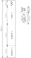
本発明の実施の形態に係る音声送受信システムの構成を図1に示す。図示するように、この音声送受信システムは、送受信機TR1及びTR2より構成されている。送受信機TR1及びTR2は、外部のパケット網などを含む外部の伝送路Lを介し、両者相互間で音声の送受信を行うものである。
Embodiments of the present invention will be described below with reference to the drawings, taking a voice transmission / reception system as an example.
FIG. 1 shows the configuration of an audio transmission / reception system according to an embodiment of the present invention. As shown in the figure, this voice transmission / reception system is composed of transceivers TR1 and TR2. The transceivers TR1 and TR2 perform voice transmission / reception between the two via an external transmission line L including an external packet network.
送受信機TR1及びTR2は互いに実質的に同一の構成を有しており、それぞれ、送信装置Tと、受信装置Rとを備えている。
送受信機TR1の送信装置Tは、音声を表すFSK(Frequency Shift Keying)変調波を生成して送受信機TR2の受信装置Rに宛てて送信し、送受信機TR2の受信装置Rは、このFSK変調波を受信して音声を再生する。同様に、送受信機TR2の送信装置Tは、音声を表すFSK変調波を生成して送受信機TR1の受信装置Rに宛てて送信し、送受信機TR1の受信装置Rは、このFSK変調波を受信して音声を再生する。
The transceivers TR1 and TR2 have substantially the same configuration, and each includes a transmission device T and a reception device R.
The transmitting device T of the transceiver TR1 generates an FSK (Frequency Shift Keying) modulated wave representing the sound and transmits it to the receiving device R of the transceiver TR2, and the receiving device R of the transceiver TR2 transmits this FSK modulated wave. Is received and the sound is played back. Similarly, the transmitting device T of the transceiver TR2 generates an FSK modulated wave representing sound and transmits it to the receiving device R of the transceiver TR1, and the receiving device R of the transceiver TR1 receives this FSK modulated wave. And play the sound.
送受信機TR1及びTR2の送信装置Tは互いに実質的に同一の構成を有しており、送受信機TR1及びTR2の受信装置Rも、互いに実質的に同一の構成を有している。
ただし、送受信機TR1及びTR2は、それぞれ、自己の送信装置Tが送信したFSK変調波が自己の受信装置Rにより受信されないような構成を有しているものとする。具体的には、例えば、送受信機TR1(又はTR2)の送信装置Tの送信周波数と受信装置Rの受信周波数とを互いに異ならせておくことが考えられる。あるいは、送受信機TR1及びTR2は、各自の送信装置Tが送信するFSK変調波に送信元及び/又は宛先の識別符号を付すものとし、一方で、各自の受信装置Rは、宛先として自己の識別符号が付されたFSK変調波、又は送信元として自己の識別符号が付されていないFSK変調波のみを、音声を再生する対象として扱うようにしてもよい。あるいは、送受信機TR1及びTR2がそれぞれ、自己のの送信装置TがFSK変調波を送信している間は自己の受信装置RがFSK変調波を受信する動作を停止させるようなPTT(Press To Talk)の機能を行う公知の機構を有するようにしてもよい。(ただしこの場合、送受信機TR1及びTR2は両者間では半二重通信を行うこととなる。)
The transmitters T of the transceivers TR1 and TR2 have substantially the same configuration, and the receivers R of the transceivers TR1 and TR2 have substantially the same configuration.
However, it is assumed that the transceivers TR1 and TR2 each have a configuration in which the FSK modulated wave transmitted by the own transmission device T is not received by the own reception device R. Specifically, for example, it is conceivable that the transmission frequency of the transmission device T of the transceiver TR1 (or TR2) is different from the reception frequency of the reception device R. Alternatively, the transceivers TR1 and TR2 attach the identification code of the transmission source and / or the destination to the FSK modulated wave transmitted by the respective transmission device T, while the respective reception device R identifies itself as the destination. Only the FSK modulated wave to which the code is attached or the FSK modulated wave to which the self identification code is not attached as the transmission source may be handled as a target for reproducing the sound. Alternatively, the PTT (Press To Talk) in which each of the transceivers TR1 and TR2 stops the operation of the receiving device R receiving the FSK modulated wave while the transmitting device T is transmitting the FSK modulated wave. It is also possible to have a known mechanism that performs the function of (However, in this case, the transceivers TR1 and TR2 perform half-duplex communication between them.)
送受信機TR1及びTR2の送信装置Tは、それぞれ、図2に示すように、音声入力部T1と、通信品質判定部T2と、ボコーダ部T3と、インターリーブ処理部T4と、ベースバンド信号生成部T5と、変調部T6と、高周波出力部T7とより構成されている。 As shown in FIG. 2, each of the transmission devices T of the transceivers TR1 and TR2 includes a voice input unit T1, a communication quality determination unit T2, a vocoder unit T3, an interleave processing unit T4, and a baseband signal generation unit T5. And a modulation unit T6 and a high-frequency output unit T7.
音声入力部T1は、例えば、マイクロフォン、AF(Audio Frequency)増幅器、サンプラー、A/D(Analog-to-Digital)コンバータ、及びフレーム生成用の論理回路などより構成されている。 The audio input unit T1 includes, for example, a microphone, an AF (Audio Frequency) amplifier, a sampler, an A / D (Analog-to-Digital) converter, and a frame generation logic circuit.
音声入力部T1は、例えば、音声を集音してこの音声を表すアナログ形式の音声信号を生成し、この音声信号を増幅し、サンプリングしてA/D変換することにより、デジタル形式の音声データを生成する。そして、このデジタル形式の音声データを複数のフレームの列へと分解して、ボコーダ部T3に供給する。
音声入力部T1が生成する各々のフレームは、音声入力部T1が集音した音声を一定の周期で(例えば、20ミリ秒毎に)区切って得られる音片1個分の波形を表す音声データからなる。
For example, the audio input unit T1 collects audio, generates an analog audio signal representing the audio, amplifies the audio signal, performs sampling and A / D conversion, and thereby converts the audio data in digital format. Is generated. Then, the audio data in the digital format is decomposed into a plurality of frames, and supplied to the vocoder unit T3.
Each frame generated by the voice input unit T1 is voice data representing a waveform of one sound piece obtained by dividing the voice collected by the voice input unit T1 at a constant cycle (for example, every 20 milliseconds). Consists of.
通信品質判定部T2は、伝送路Lの品質(通信品質)を判定し、判定結果を示す通信品質データを生成してボコーダ部T3へと供給する。 The communication quality determination unit T2 determines the quality (communication quality) of the transmission line L, generates communication quality data indicating the determination result, and supplies the communication quality data to the vocoder unit T3.
通信品質判定部T2は、具体的には、例えば、当該通信品質判定部T2が送受信機TR1に属するものであるとすれば送受信機TR2の送信装置Tが送出するFSK変調波の強度を測定し、測定結果が所定の閾値を超えているか否かを示すデータを通信品質データとして生成し供給する。この場合、通信品質判定部T2は、例えば、同調回路と、高周波増幅回路と、コンパレータとより構成されていればよい。なお、受信装置Rを構成する同調回路や高周波増幅回路が、通信品質判定部T2の機能の少なくとも一部を行ってもよい。 Specifically, for example, if the communication quality determination unit T2 belongs to the transceiver TR1, the communication quality determination unit T2 measures the intensity of the FSK modulated wave transmitted by the transmission device T of the transceiver TR2. Then, data indicating whether or not the measurement result exceeds a predetermined threshold is generated and supplied as communication quality data. In this case, the communication quality determination unit T2 may be configured by, for example, a tuning circuit, a high frequency amplifier circuit, and a comparator. Note that a tuning circuit and a high-frequency amplifier circuit constituting the receiving device R may perform at least a part of the function of the communication quality determination unit T2.
通信品質判定部T2は、FSK変調波の強度の測定結果を示すデータを通信品質データとして生成する場合、より具体的には、例えば、FSK変調波の強度の測定値が、(1)所定の閾値Th1未満であるか、(2)閾値Th1以上であり、かつ、閾値Th1より値の大きな所定の閾値Th2未満であるか、又は(3)閾値Th2以上であるか、を判別し、判別結果が(1)〜(3)のいずれに合致するかを示すデータを、通信品質データとして生成する。 When the communication quality determination unit T2 generates data indicating the measurement result of the intensity of the FSK modulated wave as the communication quality data, more specifically, for example, the measured value of the intensity of the FSK modulated wave is (1) a predetermined value. It is determined whether it is less than the threshold Th1, (2) is greater than or equal to the threshold Th1, and is less than a predetermined threshold Th2 that is greater than the threshold Th1, or (3) is greater than or equal to the threshold Th2. Is generated as communication quality data indicating which of (1) to (3) matches.
ボコーダ部T3、インターリーブ処理部T4及びベースバンド信号生成部T5は、いずれも、DSP(Digital Signal Processor)やCPU(Central Processing Unit)等のプロセッサや、このプロセッサが実行するためのプログラムを記憶するメモリなどより構成されている。なお、ボコーダ部T3、インターリーブ処理部T4及びベースバンド信号生成部T5の一部又は全部の機能を単一のプロセッサが行うようにしてもよい。また、ボコーダ部T3、インターリーブ処理部T4及びベースバンド信号生成部T5の一部又は全部の機能を行うプロセッサが更に音声入力部T1のフレーム生成用の論理回路の機能を行うようにしてもよい。 The vocoder unit T3, the interleave processing unit T4, and the baseband signal generation unit T5 are all processors such as DSPs (Digital Signal Processors) and CPUs (Central Processing Units), and memories that store programs to be executed by the processors. Etc. Note that a single processor may perform a part or all of the functions of the vocoder unit T3, the interleave processing unit T4, and the baseband signal generation unit T5. Further, a processor that performs some or all of the functions of the vocoder unit T3, the interleave processing unit T4, and the baseband signal generation unit T5 may further perform the function of a logic circuit for frame generation of the audio input unit T1.
ボコーダ部T3は、音声入力部T1よりフレームを供給されると、供給された各々のフレームにつき、当該フレームを用いて後述のボコーダ出力データを生成し、上述のフレームの列内での各フレームの順序を特定できる態様でインターリーブ処理部T4へと供給する。(具体的には、例えば、各フレームをこの順序に従って順次に供給するようにしたり、あるいは、フレームの順序を示すデータをフレームと共に供給したりすればよい。) When a frame is supplied from the voice input unit T1, the vocoder unit T3 generates vocoder output data to be described later using the frame for each supplied frame, and the vocoder unit T3 It supplies to the interleave process part T4 in the aspect which can specify an order. (Specifically, for example, the frames may be sequentially supplied in this order, or data indicating the order of the frames may be supplied together with the frames.)
各々のボコーダ出力データは、例えば、データ構造を図3に示すように、18ビットの最重要音声データと、26ビットの非保護音声データと、23ビットの非重要データと、5ビットの誤り検出用データとを含んでいる。 Each vocoder output data includes, for example, the most important voice data of 18 bits, unprotected voice data of 26 bits, unimportant data of 23 bits, and error detection of 5 bits as shown in FIG. Data.
ボコーダ出力データの最重要音声データは、当該ボコーダ出力データの生成に用いたフレームが表す音片を符号化して得られる62ビットのデータ(以下、符号化音声データと呼ぶ)のうち、所定の基準に従って特定される聴覚上の重要度が最も高い18ビットの部分より構成されている。また、当該ボコーダ出力データの非保護音声データは、当該符号化音声データのうち、最重要音声データをなす部分に次いで聴覚上の重要度が高い26ビットの部分より構成されている。 The most important voice data of the vocoder output data is a predetermined standard out of 62-bit data (hereinafter referred to as encoded voice data) obtained by encoding a sound piece represented by a frame used to generate the vocoder output data. Is composed of an 18-bit portion having the highest auditory importance. The unprotected voice data of the vocoder output data is composed of a 26-bit portion having the highest auditory importance after the portion forming the most important voice data in the encoded voice data.
符号化音声データは、音声が含み得る成分(例えば、音圧やピッチなど)に対応付けられたビットより構成されており、これらのビットの各々は、値“0”をとる場合、当該ビットに対応付けられた成分が、当該ビットを含む符号化音声データが表す音片内に実質上存在しないことを示しているものである。 The encoded speech data is composed of bits associated with components that can be included in speech (for example, sound pressure, pitch, etc.). When each of these bits takes the value “0”, This indicates that the associated component does not substantially exist in the sound piece represented by the encoded speech data including the bit.
なお、ボコーダ部T3が音片を符号化する手法は、符号化の結果得られるデータをなす各ビットの聴覚上の重要度を所定の基準に従って特定し、最重要音声データ、非保護音声データ及びその他のうちいずれかへと振り分けることが可能な手法である必要がある。ただし、このような振り分けが可能である限り、ボコーダ部T3が音片を符号化する手法は任意である。具体的には、ボコーダ部T3は例えば、線形予測符号化などの手法を用いてこの符号化を行えばよい。この場合ボコーダ部T3は、聴覚上の重要度を、例えば非特許文献1の第2分冊p982−984に示すような公知の基準により特定すればよい。
The method in which the vocoder unit T3 encodes the sound piece specifies the auditory importance of each bit constituting the data obtained as a result of encoding according to a predetermined standard, and the most important voice data, unprotected voice data, and It must be a technique that can be assigned to one of the other. However, as long as such distribution is possible, the method by which the vocoder unit T3 encodes the sound piece is arbitrary. Specifically, the vocoder unit T3 may perform this encoding using a technique such as linear predictive encoding. In this case, the vocoder unit T3 may specify the auditory importance according to a known standard as shown in the second volume p982-984 of
一方、ボコーダ出力データの非重要データは、18ビットの共用データと、5ビットの誤り検出用データ保護データとより構成されている。このうち、誤り検出用データ保護データを構成する各ビットの値はいずれも“0”である。 On the other hand, the non-important data of the vocoder output data is composed of 18-bit shared data and 5-bit error detection data protection data. Among these, the value of each bit constituting the error detection data protection data is “0”.
これに対し、共用データの値は、通信品質判定部T2より供給される通信品質データが示す伝送路Lの通信品質に応じて変わる。具体的には、共用データは、例えば通信品質が所定の基準に達していない場合は、値がいずれも“0”である18ビットのデータより構成される。一方、通信品質が当該基準に達している場合は、例えば、当該ボコーダ出力データの生成に用いた符号化音声データのうち、当該ボコーダ出力データに含まれる最重要音声データ及び非保護音声データを除いた、聴覚上の重要度が最も低い18ビットの部分より構成される。 On the other hand, the value of the shared data changes according to the communication quality of the transmission path L indicated by the communication quality data supplied from the communication quality determination unit T2. Specifically, the shared data is composed of 18-bit data whose value is “0” when the communication quality does not reach a predetermined standard. On the other hand, when the communication quality has reached the standard, for example, the most important voice data and unprotected voice data included in the vocoder output data are excluded from the encoded voice data used to generate the vocoder output data. It is composed of an 18-bit portion having the lowest auditory importance.
一方、ボコーダ出力データの誤り検出用データは、当該ボコーダ出力データに含まれる最重要音声データを用いて得られる、当該最重要音声データの誤り検出を行うためのCRC(Cycle Redundancy Check)データより構成されている。 On the other hand, the error detection data of the vocoder output data is composed of CRC (Cycle Redundancy Check) data for performing error detection of the most important voice data obtained by using the most important voice data included in the vocoder output data. Has been.
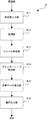
ボコーダ出力データ、特に非重要データの内容を上述した通りの内容とするため、ボコーダ部T3は、具体的には、例えば図4に示す手順でボコーダ出力データを作成し、インターリーブ処理部T4へと順次供給する。 In order to make the contents of the vocoder output data, particularly the unimportant data, as described above, the vocoder unit T3 specifically creates the vocoder output data by the procedure shown in FIG. 4, for example, and sends it to the interleave processing unit T4. Supply sequentially.
すなわち、ボコーダ部T3はまず、通信品質判定部T2が供給する通信品質データを取得し(図4,ステップS1)、この通信品質データが示すFSK変調波の強度の測定値が上述の閾値Th1以上であるか否か(つまり、上述の(2)又は(3)の条件に該当するか否か)を判別する(ステップS2)。そして、FSK変調波の強度の測定値が閾値Th1以上であると判別すると、ボコーダ部T3は処理をステップS6に移す。 That is, the vocoder unit T3 first acquires the communication quality data supplied by the communication quality determination unit T2 (FIG. 4, step S1), and the measured value of the intensity of the FSK modulated wave indicated by the communication quality data is equal to or greater than the above-described threshold Th1. (That is, whether or not the condition (2) or (3) described above is met) is determined (step S2). If it is determined that the measured value of the intensity of the FSK modulated wave is greater than or equal to the threshold Th1, the vocoder unit T3 moves the process to step S6.
一方、FSK変調波の強度の測定値が閾値Th1未満であるとステップS2で判別すると、ボコーダ部T3は、まだボコーダ出力データの作成に用いられていないフレームのうち先頭のフレームを用いて、非重要データを構成する各ビットの値がいずれも“0”であるようなボコーダ出力データを生成し、インターリーブ処理部T4へと供給する(ステップS3)。 On the other hand, if it is determined in step S2 that the measured value of the intensity of the FSK modulated wave is less than the threshold value Th1, the vocoder unit T3 uses the first frame among the frames not yet used for creating the vocoder output data. Vocoder output data in which the value of each bit constituting the important data is “0” is generated and supplied to the interleave processing unit T4 (step S3).
ステップS3の処理の次に、ボコーダ部T3は、通信品質判定部T2より通信品質データを取得し(ステップS4)、この通信品質データが示すFSK変調波の強度の測定値が上述の閾値Th2以上であるか否か(つまり、上述の(3)の条件に該当するか否か)を判別する(ステップS5)。そしてボコーダ部T3は、FSK変調波の強度の測定値が閾値Th2未満であるとステップS5で判別すると処理をステップS3に戻し、一方で閾値Th2以上であると判別すると、処理をステップS6に進める。 Following the processing in step S3, the vocoder unit T3 acquires communication quality data from the communication quality determination unit T2 (step S4), and the measured value of the intensity of the FSK modulated wave indicated by the communication quality data is equal to or greater than the above-described threshold Th2. (That is, whether or not the condition (3) is met) is determined (step S5). If the vocoder T3 determines that the measured value of the intensity of the FSK modulated wave is less than the threshold Th2 in Step S5, the process returns to Step S3. If the vocoder T3 determines that the measured value of the FSK modulated wave is greater than or equal to the threshold Th2, the process proceeds to Step S6. .
ステップS6でボコーダ部T3は、まだボコーダ出力データの作成に用いられていないフレームのうち先頭のフレームを用いてボコーダ出力データを生成し、インターリーブ処理部T4へと供給し(ステップS6)、ステップS1へと処理を戻す。ただしステップS6では、当該フレームを用いて生成した符号化音声データのうち、当該最重要音声データ及び当該非保護音声データをなす部分を除いた部分を、非重要データとして扱う。 In step S6, the vocoder unit T3 generates vocoder output data using the first frame among the frames not yet used for creating the vocoder output data, and supplies it to the interleave processing unit T4 (step S6), step S1. Return processing to. However, in step S6, the encoded audio data generated using the frame, except for the most important audio data and the portion that forms the non-protected audio data, is handled as non-important data.
インターリーブ処理部T4は、ボコーダ部T3より供給されたボコーダ出力データにインターリーブを施す。そして、インターリーブされたボコーダ出力データ(以下、インターリーブ済みフレームと記す)を、ベースバンド信号生成部T5へと供給する。 The interleave processing unit T4 performs interleaving on the vocoder output data supplied from the vocoder unit T3. Then, the interleaved vocoder output data (hereinafter referred to as an interleaved frame) is supplied to the baseband signal generation unit T5.
すなわち、インターリーブ処理部T4は、ボコーダ部T3よりボコーダ出力データを供給されると、まず、このボコーダ出力データに基づいて、4値FSKにおけるシンボルに相当する2ビットのデータを生成する。具体的には、インターリーブ処理部T4は、例えば図5にも示すように、以下(A1)〜(A3)として示す処理を行う。つまり、
(A1) このボコーダ出力データに含まれる最重要音声データを構成する各ビットと、共用データを構成する各ビットとを1対1に結合することにより、2ビットのデータを18個生成する。ただし、図5(b)に示すように、これら18個のデータは、いずれも、共用データを構成する方のビットが下位ビットとなるように結合されるものとする。
(A2) このボコーダ出力データに含まれる誤り検出用データを構成する各ビットと、誤り検出用データ保護データを構成する各ビットとを1対1に結合することにより、2ビットのデータを5個生成する。ただし、図5(b)に示すように、これら5個のデータは、いずれも、誤り検出用データ保護データを構成する方のビットが下位ビットとなるように結合されるものとする。
(A3) このボコーダ出力データに含まれる非保護音声データを、図5(a)に示すように、2ビットのデータ13個へと分解する。
That is, when interleave processing unit T4 is supplied with vocoder output data from vocoder unit T3, first, based on this vocoder output data, interleave processing unit T4 generates 2-bit data corresponding to a symbol in quaternary FSK. Specifically, the interleave processing unit T4 performs the processes indicated as (A1) to (A3) below, for example, as shown in FIG. That means
(A1) Eighteen pieces of 2-bit data are generated by one-to-one coupling each bit constituting the most important voice data included in the vocoder output data and each bit constituting the shared data. However, as shown in FIG. 5B, these 18 pieces of data are all combined so that the bit constituting the shared data becomes the lower bit.
(A2) By combining each bit constituting error detection data included in this vocoder output data and each bit constituting error protection data protection data in a one-to-one relationship, five pieces of 2-bit data Generate. However, as shown in FIG. 5B, these five pieces of data are all combined so that the bit constituting the error detection data protection data becomes the lower bit.
(A3) The unprotected voice data included in the vocoder output data is decomposed into 13 pieces of 2-bit data as shown in FIG.
そして、インターリーブ処理部T4は、(A1)〜(A3)の処理の結果得られた合計36個の2ビットデータを、例えば図5(c)に示すように、(A1)又は(A2)の処理で得られた2ビットデータと(A3)の処理で得られた2ビットデータとが交互に並ぶ部分を含むような所定の順序で、ベースバンド信号生成部T5へと供給する。 Then, the interleave processing unit T4 generates a total of 36 pieces of 2-bit data obtained as a result of the processes (A1) to (A3), as shown in FIG. 5C, for example, as shown in (A1) or (A2). The 2-bit data obtained by the process and the 2-bit data obtained by the process (A3) are supplied to the baseband signal generation unit T5 in a predetermined order including a portion in which the 2-bit data are alternately arranged.
インターリーブ処理部T4が上述の処理を行って生成する2ビットデータは、誤り検出用データ及び誤り検出用データ保護データより得られるものについては、いずれも下位1桁が“0”である。また、共用データの全ビットの値が“0”である場合は、最重要音声データ及び共用データより得られるものについても、いずれも下位1桁が“0”となる。これに対し、非保護音声データより得られる2ビットデータは、下位1桁が“0”又は“1”のいずれでもあり得る。 As for the 2-bit data generated by the interleave processing unit T4 performing the above-described processing, the lower one digit is “0” for data obtained from the error detection data and the error detection data protection data. When the value of all the bits of the shared data is “0”, both the most important voice data and the data obtained from the shared data have “0” in the lower one digit. On the other hand, 2-bit data obtained from unprotected audio data may have either “0” or “1” in the lower 1 digit.
ベースバンド信号生成部T5は、インターリーブ処理部T4よりインターリーブ済みフレームを供給されると、このインターリーブ済みフレームを、4値のルートナイキストFSKにおけるベースバンド信号へと変換し、このベースバンド信号を変調部T6へと供給する。なお、ベースバンド信号生成部T5は、ベースバンド信号に、例えば、1個のインターリーブ済みフレームを表す部分の始点及び終点を識別するためのマーカーとなる信号を挿入してもよい。 When the interleaved frame is supplied from the interleave processing unit T4, the baseband signal generation unit T5 converts the interleaved frame into a baseband signal in quaternary root Nyquist FSK, and the baseband signal is modulated by the modulation unit. Supply to T6. Note that the baseband signal generation unit T5 may insert, for example, a signal serving as a marker for identifying a start point and an end point of a portion representing one interleaved frame into the baseband signal.
図6は、ベースバンド信号生成部T5が生成するベースバンド信号のアイパターンの一例を示す図である。図示するように、このベースバンド信号は、1シンボル区間(シンボル1個分の情報を表す区間)内の一定の位相の点(ナイキスト点)で、瞬時値が4個の値のいずれかへと収束する。これらの4個の値(以下、シンボル値と呼ぶ)は、大きい方から2番目の値を(+1)とすると、例えば、図6に示すように値が大きい方から順に(+3),(+1),(−1),(−3)の各値をとって等間隔で並ぶものである。 FIG. 6 is a diagram illustrating an example of an eye pattern of a baseband signal generated by the baseband signal generation unit T5. As shown in the figure, this baseband signal has a constant phase point (Nyquist point) in one symbol section (section representing information for one symbol), and the instantaneous value becomes one of four values. Converge. Of these four values (hereinafter referred to as symbol values), assuming that the second value from the largest value is (+1), for example, as shown in FIG. ), (-1), and (-3) are taken at equal intervals.
そして、ベースバンド信号生成部T5は例えば、図6に示すように、インターリーブ済みフレームに含まれるシンボル“00”(つまり、値“00”を有する2ビットデータ)を、シンボル値が(−3)であるシンボル区間へと変換し、シンボル“01”を、シンボル値が(−1)であるシンボル区間へと変換し、シンボル“11”を、シンボル値が(+1)であるシンボル区間へと変換し、シンボル“10”を、シンボル値が(+3)であるシンボル区間へと変換するものとする。 Then, for example, as illustrated in FIG. 6, the baseband signal generation unit T5 uses the symbol “00” (that is, 2-bit data having the value “00”) included in the interleaved frame, and the symbol value is (−3). Is converted to a symbol interval having a symbol value of (−1), and the symbol “11” is converted to a symbol interval having a symbol value of (+1). It is assumed that the symbol “10” is converted into a symbol interval whose symbol value is (+3).
インターリーブ済みフレームからベースバンド信号への変換が上述の規則に従って行われる結果、下位1桁が“0”であるシンボルは、シンボル値が(−3)又は(+3)であるシンボル区間へと変換される。従って、誤り検出用データや、通信品質が所定の基準を満たさないような悪い状態における最重要音声データを表すシンボルは、いずれも、シンボル値が(+3)又は(−3)であるシンボル区間へと変換されることとなる。これに対し、非保護音声データや、通信品質が良い状態における最重要音声データを表すシンボルは、(+3),(+1),(−1)又は(−3)のいずれのシンボル値をとるシンボル区間へも変換され得る。 As a result of the conversion from the interleaved frame to the baseband signal in accordance with the above-mentioned rule, the symbol having the lower one digit “0” is converted into a symbol interval whose symbol value is (−3) or (+3). The Therefore, both the error detection data and the symbol representing the most important voice data in a bad state where the communication quality does not satisfy the predetermined standard are all to the symbol interval whose symbol value is (+3) or (-3). Will be converted. On the other hand, the symbol representing unprotected voice data or the most important voice data in a state where the communication quality is good takes any symbol value of (+3), (+1), (−1) or (−3). It can also be converted to an interval.
なお、以上より明らかなように、インターリーブ済みフレームからベースバンド信号への変換を上述の規則に従って行う場合、これら4種類のシンボルは、シンボル値が高い順(又は低い順)に配列すると、グレイ符号の系列をなすようになっている(つまり、この配列内で隣り合うシンボル間のハミング距離がいずれも1である)。 As is clear from the above, when the conversion from the interleaved frame to the baseband signal is performed according to the above-described rules, these four types of symbols are arranged in the order of increasing symbol values (or in ascending order). (That is, the hamming distance between adjacent symbols in this array is 1).
変調部T6は、公知の周波数変調回路や、搬送波を生成する発振回路などより構成されており、ベースバンド信号生成部T5より供給されたベースバンド信号を用いて搬送波を周波数変調し、得られたFSK(ルートナイキストFSK)変調波を、高周波出力部T7へと供給する。 The modulation unit T6 includes a known frequency modulation circuit, an oscillation circuit that generates a carrier wave, and the like, and is obtained by frequency-modulating the carrier wave using the baseband signal supplied from the baseband signal generation unit T5. An FSK (Root Nyquist FSK) modulated wave is supplied to the high-frequency output unit T7.
なお、変調部T6も、プロセッサや、このプロセッサが実行するためのプログラムを記憶するメモリなどより構成されていてよい。また、音声入力部T1、ボコーダ部T3、インターリーブ処理部T4及びベースバンド信号生成部T5の一部又は全部の機能を行うプロセッサが更に変調部T6の機能を行うようにしてもよい。 Note that the modulation unit T6 may also include a processor, a memory that stores a program to be executed by the processor, and the like. Further, a processor that performs a part or all of the functions of the voice input unit T1, the vocoder unit T3, the interleave processing unit T4, and the baseband signal generation unit T5 may further perform the function of the modulation unit T6.
高周波出力部T7は、高周波増幅回路やアンテナ等より構成されており、変調部T6より供給された変調波を増幅して伝送路Lへと送出する。 The high-frequency output unit T7 includes a high-frequency amplifier circuit, an antenna, and the like. The high-frequency output unit T7 amplifies the modulated wave supplied from the modulation unit T6 and sends it to the transmission line L.
送信装置Tは、以上説明した動作を行うことにより、自己が集音した音声を表す、ルートナイキスト特性を有するFSK変調波を生成して送信する。
このFSK変調波のベースバンド信号が表すシンボルは、符号化音声データの最重要部分を表す第1の種類のシンボルと、符号化音声データの最重要部分の誤り検出用のデータを表す第2の種類のシンボルと、符号化音声データの最重要部分以外を表す第3の種類のシンボルと、に分類され得る。そして、第2の種類のシンボルを表すシンボル区間のシンボル値は、ベースバンド信号のシンボル区間がとり得る4個のシンボル値のうちの最大値又は最小値となる。また、伝送路Lの通信品質が所定の基準を満たさないときは、第1の種類のシンボルを表すシンボル区間のシンボル値も、とり得る4個の値のうちの最大値又は最小値となる。このため、第2の種類のシンボル(又は、伝送路Lの通信品質が所定の基準を満たさない場合における第1及び第2の種類のシンボル)のみについてみれば、符号化音声データの最重要部分又はその誤り検出用のデータをなすビットに冗長なビットが付加された形となっている結果、とり得るシンボル値が2個となる一方で、シンボル値の間隔が実質的に拡大されており、この結果として信号対雑音比が向上する。
By performing the operation described above, the transmission device T generates and transmits an FSK modulated wave having root Nyquist characteristics that represents the sound collected by itself.
The symbols represented by the baseband signal of the FSK modulated wave include a first type symbol representing the most important part of the encoded speech data and a second symbol representing data for error detection of the most important part of the encoded speech data. It can be classified into a type of symbol and a third type of symbol representing other than the most important part of the encoded audio data. The symbol value of the symbol interval representing the second type symbol is the maximum value or the minimum value of the four symbol values that can be taken by the symbol interval of the baseband signal. Further, when the communication quality of the transmission line L does not satisfy a predetermined standard, the symbol value of the symbol section representing the first type symbol is also the maximum value or the minimum value among the four possible values. Therefore, if only the second type symbols (or the first and second type symbols when the communication quality of the transmission line L does not satisfy the predetermined standard) are considered, the most important part of the encoded speech data Or, as a result of redundant bits added to the bits constituting the error detection data, the possible symbol values are two, while the interval between the symbol values is substantially expanded. As a result, the signal-to-noise ratio is improved.
また、上述した本実施の形態の送信装置Tは、第1の種類のシンボルを表すシンボル区間と、第3の種類のシンボルを表すシンボル区間とが交互に並ぶ部分を含むように、ベースバンド信号を生成する結果、重要度の高い第1の種類のシンボルがベースバンド信号内に分散する。このため、伝送される変調波がフェージング等の影響を受けても、重要度の高い第1の種類のシンボルが多数まとめて欠落する危険が少ない。 In addition, the transmission apparatus T according to the present embodiment described above includes a baseband signal so as to include a portion in which a symbol period representing the first type symbol and a symbol period representing the third type symbol are alternately arranged. As a result, the first type symbols having high importance are dispersed in the baseband signal. For this reason, even if the modulated wave to be transmitted is affected by fading or the like, there is little risk that a large number of first-type symbols having high importance will be lost.
また、伝送路Lの通信品質が所定の基準を満たすときは、第1の種類のシンボルは、符号化音声データの最重要部分に加え、この符号化音声データのうち重要度が最も低い部分の内容も表すように設定される。このため、伝送路Lの通信品質が良いときは、音声の伝送のビットレートが実質上増大し、通信品質に応じた適切な態様での伝送が行われる。 In addition, when the communication quality of the transmission line L satisfies a predetermined standard, the first type symbol is not only the most important part of the encoded audio data but also the least important part of the encoded audio data. It is set to represent the contents. For this reason, when the communication quality of the transmission line L is good, the bit rate of audio transmission is substantially increased, and transmission is performed in an appropriate manner according to the communication quality.
また、伝送路Lの通信品質が所定の基準を満たさない場合において、第1の種類のシンボルを生成するために符号化音声データの最重要部分に付加されるビットの値(上述した例では“0”)は、符号化音声データを構成するビットが音片内に特定の成分が不存在であることを示している場合の値と同一である。
このため、送信装置Tが送信したFSK変調波を受信する装置(例えば、本実施の形態の受信装置R)は、第1の種類のシンボルを生成するために符号化音声データの最重要部分に付加されたビットを、当該符号化音声データのうち重要度が最も低い部分の内容を表すものと無条件に見なして音声再生に用いても差し支えなく、従って、このビットがいかなる種類の情報を表しているかを判別する必要もない。
Further, when the communication quality of the transmission line L does not satisfy a predetermined standard, the value of the bit added to the most important part of the encoded speech data in order to generate the first type symbol (in the above example, “ 0 ″) is the same as the value in the case where the bits constituting the encoded audio data indicate that a specific component is not present in the sound piece.
For this reason, a device that receives the FSK modulated wave transmitted by the transmitting device T (for example, the receiving device R of the present embodiment) is the most important part of the encoded speech data in order to generate the first type of symbol. The added bit can be used for audio reproduction by unconditionally considering it as the content of the least important part of the encoded audio data, and therefore this bit represents any kind of information. There is no need to determine whether or not
次に受信装置Rの説明に移ると、送受信機TR1及びTR2の受信装置Rは、それぞれ、図7に示すように、高周波入力部R1と、復調部R2と、シンボル判定部R3と、デインターリーブ処理部R4と、音声データ復元部R5と、音声出力部R6とより構成されている。 Turning now to the description of the receiving device R, the receiving devices R of the transceivers TR1 and TR2, respectively, as shown in FIG. 7, are a high frequency input unit R1, a demodulating unit R2, a symbol determining unit R3, and a deinterleaver. The processing unit R4, the audio data restoration unit R5, and the audio output unit R6 are configured.
高周波入力部R1は、アンテナや、同調回路や、高周波増幅回路より構成されており、送信装置T等が伝送路Lへと送出したFSK変調波を伝送路Lより受信し、増幅して復調部R2へと供給する。なお、送受信機TR1又はTR2が備える1個のアンテナが、当該送受信機の高周波入力部R1のアンテナの機能と、当該送受信機の高周波出力部T7のアンテナの機能とを兼ねるようにしてもよい。 The high-frequency input unit R1 includes an antenna, a tuning circuit, and a high-frequency amplifier circuit. The high-frequency input unit R1 receives the FSK modulated wave transmitted from the transmission device T or the like to the transmission line L from the transmission line L, amplifies it, and demodulates it. Supply to R2. Note that one antenna included in the transceiver TR1 or TR2 may serve as the antenna function of the high-frequency input unit R1 of the transceiver and the antenna function of the high-frequency output unit T7 of the transceiver.
復調部R2は、周波数変調波を検波する公知の検波回路より構成されており、高周波入力部R1より供給されたFSK変調波を検波することにより、ベースバンド信号を復元する。そして、復元されたベースバンド信号をシンボル判定部R3へと供給する。なお、復調部R2は、プロセッサや、このプロセッサが実行するためのプログラムを記憶するメモリなどより構成されていてもよい。 The demodulator R2 includes a known detection circuit that detects a frequency-modulated wave, and restores the baseband signal by detecting the FSK-modulated wave supplied from the high-frequency input unit R1. Then, the restored baseband signal is supplied to the symbol determination unit R3. Note that the demodulator R2 may include a processor, a memory that stores a program to be executed by the processor, and the like.
シンボル判定部R3、デインターリーブ処理部R4及び音声データ復元部R5は、いずれも、プロセッサや、このプロセッサが実行するためのプログラムを記憶するメモリなどより構成されている。なお、シンボル判定部R3、デインターリーブ処理部R4及び音声データ復元部R5の一部又は全部の機能を単一のプロセッサが行うようにしてもよい。また、復調部R1や送信装置Tの一部又は全部の機能を行うプロセッサが更にシンボル判定部R3、デインターリーブ処理部R4及び音声データ復元部R5の一部又は全部の機能を行うようにしてもよい。 Each of the symbol determination unit R3, the deinterleave processing unit R4, and the audio data restoration unit R5 includes a processor and a memory that stores a program to be executed by the processor. A single processor may perform some or all of the functions of the symbol determination unit R3, the deinterleave processing unit R4, and the audio data restoration unit R5. Further, a processor that performs a part or all of the functions of the demodulation unit R1 and the transmission device T may further perform a part or all of the functions of the symbol determination unit R3, the deinterleave processing unit R4, and the audio data restoration unit R5. Good.
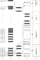
シンボル判定部R3は、図8(a)及び(b)に模式的に示すように、復調部R2より供給されたベースバンド信号の各ナイキスト点における瞬時値に基づいて、それぞれのナイキスト点を含むシンボル区間が表すシンボルを判定し、判定結果に基づいて、送信装置Tのインターリーブ処理部T4が生成するインターリーブ済みフレームに相当するデータ(図8(b))を再生する。そして、再生されたデータをデインターリーブ処理部R4へと供給する。 As schematically shown in FIGS. 8A and 8B, the symbol determination unit R3 includes each Nyquist point based on the instantaneous value at each Nyquist point of the baseband signal supplied from the demodulation unit R2. The symbol represented by the symbol section is determined, and based on the determination result, the data corresponding to the interleaved frame generated by the interleave processing unit T4 of the transmission device T (FIG. 8B) is reproduced. Then, the reproduced data is supplied to the deinterleave processing unit R4.
具体的には、シンボル判定部R3は、例えばまず、復調部R2より供給されたベースバンド信号に含まれるそれぞれのナイキスト点について、当該ナイキスト点におけるベースバンド信号の瞬時値が第1の閾値(Th+)以上であるか、第2の閾値(Th0)以上()Th+)未満であるか、第3の閾値(Th−)以上(Th0)未満であるか、又は(Th−)未満であるか、を判別する。
ただし、(Th+)の値は(+1)を超え(+3)未満であり、(Th0)の値は(−1)を超え(+1)未満であり、(Th−)の値は(−3)を超え(−1)未満であるものとする。従って具体的には、(Th+)の値は例えば(+2)、(Th0)の値は例えば(0)、(Th−)の値は例えば(−2)であればよい。
Specifically, for example, for each Nyquist point included in the baseband signal supplied from the demodulation unit R2, the symbol determination unit R3 first sets the instantaneous value of the baseband signal at the Nyquist point to the first threshold (Th + ) Or more, a second threshold value (Th0) or more and less than () Th +), a third threshold value (Th−) or more and less than (Th0), or less than (Th−), Is determined.
However, the value of (Th +) is greater than (+1) and less than (+3), the value of (Th0) is greater than (−1) and less than (+1), and the value of (Th−) is (−3) And less than (-1). Therefore, specifically, the value of (Th +) may be (+2), the value of (Th0) may be (0), for example, and the value of (Th−) may be (−2), for example.
そして、シンボル判定部R3は、ナイキスト点におけるベースバンド信号の瞬時値が(Th+)以上であると判別すると、当該ナイキスト点を含むシンボル区間のシンボル値が(+3)であり(図8(a))、従って当該シンボル区間がシンボル“10”を表すものである、と判定する。
同様に、(Th0)以上(Th+)未満であると判別すると、当該ナイキスト点を含むシンボル区間のシンボル値が(+1)であり、従って当該シンボル区間がシンボル“11”を表すものである、と判定する。また、(Th−)以上(Th0)未満であると判別すると、当該ナイキスト点を含むシンボル区間のシンボル値が(−1)であり、従って当該シンボル区間がシンボル“01”を表すものである、と判定する。また、(Th−)未満であると判別すると、当該ナイキスト点を含むシンボル区間のシンボル値が(−3)であり、従って当該シンボル区間がシンボル“00”を表すものである、と判定する。
When the symbol determination unit R3 determines that the instantaneous value of the baseband signal at the Nyquist point is equal to or greater than (Th +), the symbol value of the symbol section including the Nyquist point is (+3) (FIG. 8A). Therefore, it is determined that the symbol section represents the symbol “10”.
Similarly, if it is determined that it is greater than or equal to (Th0) and less than (Th +), the symbol value of the symbol section including the Nyquist point is (+1), and therefore the symbol section represents the symbol “11”. judge. If it is determined that the value is greater than or equal to (Th−) and less than (Th0), the symbol value of the symbol interval including the Nyquist point is (−1), and thus the symbol interval represents the symbol “01”. Is determined. If it is determined that it is less than (Th−), it is determined that the symbol value of the symbol section including the Nyquist point is (−3), and therefore the symbol section represents the symbol “00”.
そして、インターリーブ済みフレーム1個分のシンボルをすべて判定すると、シンボル判定部R3は、これらのシンボルの列を、再生されたインターリーブ済みフレーム1個に相当するデータとして、デインターリーブ処理部R4へと供給する。 When all symbols for one interleaved frame have been determined, the symbol determination unit R3 supplies the sequence of these symbols as data corresponding to one reproduced interleaved frame to the deinterleave processing unit R4. To do.
デインターリーブ処理部R4は、シンボル判定部R3より供給されたデータがインターリーブ済みフレームであるものとして、当該インターリーブ済みフレームを用い、ボコーダ出力データを復元する。そして、復元されたボコーダ出力データを音声データ復元部R5へと供給する。 The deinterleave processing unit R4 restores the vocoder output data using the interleaved frame, assuming that the data supplied from the symbol determination unit R3 is an interleaved frame. Then, the restored vocoder output data is supplied to the audio data restoration unit R5.
具体的には、デインターリーブ処理部R4は、インターリーブ済みフレームに相当するデータをシンボル判定部R3より供給されると、図8(b)〜(e)にも示すように、例えば以下に記す(B1)〜(B5)の処理を行う。すなわち、
(B1) シンボル判定部R3より供給された当該インターリーブ済みフレームに含まれる各シンボルのうち、非保護音声データを含む13個のシンボルを、全体として26ビットの非保護音声データであると特定する。なお、デインターリーブ処理部R4は、例えば、当該インターリーブ済みフレーム内での各々のシンボルの順序に基づいて、当該シンボルが含んでいるデータの種類を特定するようにすればよい。
(B2) また、当該インターリーブ済みフレームに含まれる各シンボルのうち、最重要音声データを含む18個のシンボルを、それぞれ、上位1ビットと下位1ビットとに分離する。そして、上位1ビットのデータ18個からなる18ビットのデータを最重要音声データとして特定する。
(B3) (B2)の処理で分離した下位1ビットのデータ18個からなる18ビットのデータを、非重要データのうちの共用データ(ただし、1個の符号化音声データのうち(a)の処理で特定した非保護音声データと(B2)の処理で特定した最重要音声データとを除いた部分からなるデータ)として特定する。
(B4) また、当該インターリーブ済みフレームに含まれる各シンボルのうち、誤り検出用データを含む5個のシンボルの下位1ビットをそれぞれ破棄し、残った上位1ビットのデータ5個からなる5ビットのデータを、誤り検出用データとして特定する。
(B5) (B1)〜(B4)の処理で特定された最重要音声データ、非保護音声データ、非重要データ及び誤り検出用データを互いに対応付け、ボコーダ出力データに相当するデータとして、音声データ復元部R5に供給する。
Specifically, when the data corresponding to the interleaved frame is supplied from the symbol determination unit R3, the deinterleave processing unit R4 is described below, for example, as shown in FIGS. 8B to 8E ( Processes B1) to (B5) are performed. That is,
(B1) Of the symbols included in the interleaved frame supplied from the symbol determination unit R3, 13 symbols including unprotected audio data are identified as 26-bit unprotected audio data as a whole. Note that the deinterleave processing unit R4 may specify the type of data included in the symbol based on the order of each symbol in the interleaved frame, for example.
(B2) Also, among the symbols included in the interleaved frame, 18 symbols including the most important audio data are separated into upper 1 bit and lower 1 bit, respectively. Then, 18-bit data composed of 18 upper 1-bit data is specified as the most important voice data.
(B3) 18-bit data consisting of 18 lower-order 1-bit data separated in the process of (B2) is converted into shared data of non-important data (however, in (a) of one encoded audio data) The unprotected voice data specified by the process and the data excluding the most important voice data specified by the process (B2) are specified.
(B4) Further, among the symbols included in the interleaved frame, the lower 1 bit of the 5 symbols including the error detection data is discarded, and the remaining 5 bits of 5 bits of the upper 1 bit data are discarded. The data is specified as error detection data.
(B5) The most important voice data, unprotected voice data, non-important data, and error detection data specified in the processes (B1) to (B4) are associated with each other, and voice data is obtained as data corresponding to vocoder output data. This is supplied to the restoration unit R5.
音声データ復元部R5は、デインターリーブ処理部R4より供給された、ボコーダ出力データに相当するデータを取得し、このデータに含まれる最重要音声データのうち誤っているビットを、当該データに含まれる誤り検出用データを用いて検出し、検出されたビットに、所定のバッドフレームマスキング処理を施す。 The voice data restoration unit R5 obtains data corresponding to the vocoder output data supplied from the deinterleave processing unit R4, and the erroneous bit of the most important voice data included in the data is included in the data. Detection is performed using error detection data, and a predetermined bad frame masking process is performed on the detected bits.
上述のバッドフレームマスキング処理は、具体的には、例えば、誤っているビットを、当該ビットの直前又はその他所定の条件を満たす位置のビットの値と同じ値へと変更する処理であればよい。あるいは、誤っているビットの値を、当該ビットの前後を所定の規則(例えば、ラグランジェ補間など)に従って補間するような値へと変更する処理であってもよい。あるいは、誤っているビットの値を、当該ビットに対応付けられた成分が不存在ないし破棄されたことを示す値(例えば、上述の送信装置Tが生成するボコーダ出力データの例では“0”)や、その他所定の値へと変更する処理であってもよい。 Specifically, the above-described bad frame masking process may be, for example, a process for changing an erroneous bit to the same value as the value of the bit immediately before the bit or other position satisfying a predetermined condition. Alternatively, a process of changing the value of an erroneous bit to a value that interpolates before and after the bit according to a predetermined rule (for example, Lagrange interpolation) may be performed. Alternatively, the value of the erroneous bit is a value indicating that the component associated with the bit is absent or discarded (for example, “0” in the example of the vocoder output data generated by the transmission device T described above) Alternatively, the process may be changed to a predetermined value.
そして、音声データ復元部R5は、最重要音声データの誤り検出(及び、誤りが検出された場合は更にバッドフレームマスキング処理)が完了したボコーダ出力データに含まれる当該最重要音声データ、非保護音声データ及び非重要データより構成される符号化音声データを、公知の手法により、当該符号化音声データが示す音声の波形を表すデジタル形式の音声データへと変換し、音声出力部R6へと供給する。 Then, the voice data restoration unit R5 includes the most important voice data and the unprotected voice included in the vocoder output data for which the error detection of the most important voice data (and the bad frame masking process when an error is detected) is completed. Encoded audio data composed of data and non-important data is converted into digital audio data representing the waveform of the audio indicated by the encoded audio data by a known method, and supplied to the audio output unit R6. .
符号化音声データを音声信号へと変換する手法としては、例えば、符号化音声データを構成する符号と音声データとの対応関係を記述するルックアップテーブルと、音声データのデータベースとをあらかじめ記憶しておき、このルックアップを参照して、符号化音声データ内の符号に相当する音声データを特定し、特定された音声データをデータベース等から読み出して互いに結合する、などの手法が考えられる。 As a method for converting encoded audio data into an audio signal, for example, a lookup table describing a correspondence relationship between codes constituting the encoded audio data and audio data and an audio data database are stored in advance. In addition, referring to this lookup, it is possible to identify speech data corresponding to a code in the encoded speech data, read the identified speech data from a database or the like, and combine them.
なお、上述したように、最重要音声データ内のビットと共に1個のシンボルを構成するビットは、符号化音声データのうち重要度が最も低い部分をなすビットであるか、又は、音片内の特定の成分が不存在であることを示す値を有するビットである。このため、受信装置Rは、上述の(B3)の処理で特定したデータを、当該符号化音声データのうち重要度が最も低い部分の内容を表すものと無条件に見なしても差し支えなく、換言すれば、このデータがいかなる種類のデータであるかを判別する必要はない。 As described above, the bits that form one symbol together with the bits in the most important voice data are the bits that form the least important part of the encoded voice data, or A bit having a value indicating that a particular component is absent. For this reason, the receiving apparatus R may unconditionally consider the data specified in the above-described process (B3) as representing the content of the least important part of the encoded audio data. Thus, it is not necessary to determine what kind of data this data is.
音声出力部R6は、例えば、D/A(Digital-to-Analog)コンバータ、AF増幅器及びスピーカーなどより構成されている。
音声出力部R6は、音声データ復元部R5よりデジタル形式の音声データを供給されると、例えば、この音声データをD/A変換することにより、アナログ形式の音声信号を生成する。そしてこの音声信号を増幅し、増幅された音声信号によりスピーカーを駆動することにより、この音声信号が表す音声を再生する。
The audio output unit R6 includes, for example, a D / A (Digital-to-Analog) converter, an AF amplifier, and a speaker.
When the audio output unit R6 is supplied with the digital audio data from the audio data restoration unit R5, for example, the audio output unit R6 performs D / A conversion on the audio data to generate an analog audio signal. Then, the audio signal is amplified and the speaker is driven by the amplified audio signal, thereby reproducing the audio represented by the audio signal.
受信装置Rは、以上説明した動作を行うことにより、送信装置T等が送信したFSK変調波を受信し、このFSK変調波が表す音声を再生する。
送信装置Tが送信するFSK変調波は、上述の通り、符号化音声データの最重要部分の誤り検出用のデータを表すシンボル(伝送路Lの通信品質が所定の基準を満たさない場合は、更に、当該最重要部分を表すシンボル)のとり得るシンボル値が2個となる一方で、シンボル値の間隔が実質的に拡大されている。このため、受信装置Rはこれらのシンボルを良好に復元できる。また、伝送路Lの通信品質が所定の基準を満たすときは、このFSK変調は更に、この符号化音声データのうち重要度が最も低い部分の内容も表すものとなっている。そして受信装置Rはこの部分も音声の再生に用いることができる。
By performing the operation described above, the receiving device R receives the FSK modulated wave transmitted by the transmitting device T and reproduces the sound represented by the FSK modulated wave.
As described above, the FSK modulated wave transmitted by the transmitting apparatus T is a symbol representing the error detection data of the most important part of the encoded voice data (if the communication quality of the transmission line L does not satisfy a predetermined standard, , The symbol representing the most important part) can have two symbol values, while the interval between the symbol values is substantially expanded. For this reason, the receiving apparatus R can restore these symbols satisfactorily. Further, when the communication quality of the transmission line L satisfies a predetermined standard, the FSK modulation further represents the content of the least important part of the encoded audio data. The receiving device R can also use this part for audio reproduction.
従って、送信装置T等が送信したFSK変調波を受信装置Rが受信して音声を再生した場合、例えば図9にグラフPとして示すような音声の特性が得られる。なお、図9におけるグラフP1は、符号化音声データの最重要部分やその誤り検出用のデータが、通信品質に関係なく一律に、冗長なビットを付加する上述の手順によってシンボル値が(+3)又は(−3)のシンボルへと変換されている場合における、通信品質と音質との関係を示すグラフである。また、グラフP2は、符号化音声データの最重要部分をなすビットと最も重要度が低い部分をなすビットとを、通信品質に関係なく一律に、上述した手順によって1個のシンボルとして表した場合における通信品質と音質との関係を示すグラフである。(なお、図9は、通信品質判定部T2が測定したFSK変調波の強度を通信品質の尺度として用い、また、上述した閾値Th1及びTh2が、Th1=Th2=xという関係にある場合を例示するものである。) Therefore, when the receiving device R receives the FSK modulated wave transmitted by the transmitting device T or the like and reproduces the sound, for example, a sound characteristic as shown by a graph P in FIG. In the graph P1 in FIG. 9, the symbol value is (+3) according to the above procedure in which redundant bits are uniformly added to the most important portion of the encoded speech data and the error detection data regardless of the communication quality. Or it is a graph which shows the relationship between communication quality and sound quality in the case of converting into the symbol of (-3). In the graph P2, the bit that forms the most important part of the encoded speech data and the bit that forms the least important part are uniformly represented as one symbol by the above-described procedure regardless of the communication quality. It is a graph which shows the relationship between the communication quality and sound quality in. (Note that FIG. 9 illustrates the case where the intensity of the FSK modulated wave measured by the communication quality determination unit T2 is used as a measure of communication quality, and the above-described threshold values Th1 and Th2 have a relationship of Th1 = Th2 = x. To do.)
図9から分かるように、受信装置Rは、伝送路Lの通信品質がxより悪い場合は、この場合においてグラフP2の特性より優れたグラフP1の特性で音声を再生する。一方、伝送路Lの通信品質がxより良い場合は、この場合においてグラフP1の特性より優れたグラフP2の特性で音声を再生する。このように、この音声送受信システムは、通信品質に応じて最適な音質が得られる手法で音声の伝送を行う。 As can be seen from FIG. 9, when the communication quality of the transmission line L is worse than x, the receiving device R reproduces the sound with the characteristic of the graph P1 superior to the characteristic of the graph P2 in this case. On the other hand, when the communication quality of the transmission line L is better than x, in this case, the voice is reproduced with the characteristic of the graph P2 superior to the characteristic of the graph P1. As described above, the voice transmission / reception system transmits voice by a technique that can obtain an optimum sound quality according to the communication quality.
なお、この音声送受信システムの構成は、上述のものに限られない。
例えば、送信装置T及び受信装置Rの各部のうちプロセッサより構成される部分は、プロセッサに代えて専用の電子回路より構成されていてもよい。また、音声を表す上述の各種データや、誤り検出用データのビット数は任意である。
また、伝送路Lの通信品質が所定の基準を満たすときは、共用データと同様、誤り訂正用データ保護用データも、符号化音声データのうち重要度が最も低い部分をなすビットから構成されていてよい。
In addition, the structure of this audio | voice transmission / reception system is not restricted to the above-mentioned thing.
For example, a portion configured by the processor among the units of the transmission device T and the reception device R may be configured by a dedicated electronic circuit instead of the processor. Further, the number of bits of the above-described various data representing voice and error detection data is arbitrary.
In addition, when the communication quality of the transmission line L satisfies a predetermined standard, the error correction data protection data is composed of the least significant bits of the encoded voice data as well as the shared data. It's okay.
また、ボコーダ部T3が音声を符号化する規則も任意であり、ボコーダ部T3は、符号化された音声に更にFEC(Forward Error Correction:前方向誤り訂正)等の処理を施してもよい。また、誤り検出用データは必ずしもCRC符号からなっている必要はなく、チェックサムやパリティ符号あるいはその他任意の手法により作成されてよい。あるいは、誤り検出用データに代えて誤り訂正符号が用いられてもよい。 Further, the rules for encoding the speech by the vocoder unit T3 are also arbitrary, and the vocoder unit T3 may further perform processing such as FEC (Forward Error Correction) on the encoded speech. Further, the error detection data does not necessarily have to be a CRC code, and may be created by a checksum, a parity code, or any other method. Alternatively, an error correction code may be used instead of the error detection data.
また、上述のボコーダ部T3は、共用データに含まれる音声符号化データの成分のビット数を、通信品質データが示す伝送路Lの通信品質が所定の基準に達していれば最重要音声データのビット数と同数とし、達していなければ0個とする、というように2段階に変化させている。
しかし、ボコーダ部T3は、共用データに含まれる音声符号化データの成分のビット数を、伝送路Lの通信品質が良好であるほど(例えば上述の例では、通信品質データが示すFSK変調波の強度が大きいほど)多くなるよう、3段階以上に変化させてもよい。ボコーダ部T3はこの場合、共用データのうち音声符号化データの成分を表さない残りのビットの値を、音声の特定の成分の不存在を示す値(上述の例では“0”)とすればよい。
In addition, the vocoder T3 described above determines the number of bits of the speech encoded data component included in the shared data, if the communication quality of the transmission path L indicated by the communication quality data reaches a predetermined standard. The number of bits is the same as the number of bits, and if not reached, the number is changed to two, such as 0.
However, the vocoder unit T3 sets the number of bits of the speech encoded data component included in the shared data so that the communication quality of the transmission line L is better (for example, in the above example, the FSK modulated wave indicated by the communication quality data). You may change in three steps or more so that it may increase, so that intensity | strength is large. In this case, the vocoder unit T3 sets the value of the remaining bits that do not represent the component of the speech encoded data in the shared data as a value (“0” in the above example) indicating the absence of a specific component of speech. That's fine.
また、伝送する対象のデータは必ずしも音声を表すものでなくてもよく、符号の列として表せるデータである限り任意である。従って、例えば画像を表すデータでもよい。そして、ボコーダ部T3は、伝送対象のデータのいかなる部分を最重要部分(あるいは、最も重要度が低い部分)として扱うかを、任意の基準に従って決定してよい。 The data to be transmitted does not necessarily represent voice, and is arbitrary as long as it can be represented as a code string. Therefore, for example, data representing an image may be used. Then, the vocoder unit T3 may determine which part of the transmission target data is to be treated as the most important part (or the part with the lowest importance) according to an arbitrary criterion.
また、音声入力部T1は、伝送する対象のデータを任意の手法で取得してよく、例えば、音声入力部T1はUSB(Universal Serial Bus)やIEEE1394あるいはEthernet(登録商標)等のシリアルインターフェース回路を備えるものとして、外部よりシリアル伝送されるデータをシリアルインターフェース等を介して取得してもよい。あるいは、音声入力部T1はCD(Compact Disc)−ROM(Read Only Memory)ドライブ等の記録媒体ドライブ装置を備えるものとして、伝送する対象のデータを記録した記録媒体から当該データを読み取るようにしてもよい。 The voice input unit T1 may acquire data to be transmitted by an arbitrary method. For example, the voice input unit T1 uses a serial interface circuit such as USB (Universal Serial Bus), IEEE 1394, or Ethernet (registered trademark). As a provision, data serially transmitted from the outside may be acquired via a serial interface or the like. Alternatively, the audio input unit T1 includes a recording medium drive device such as a CD (Compact Disc) -ROM (Read Only Memory) drive, and reads the data from a recording medium on which data to be transmitted is recorded. Good.
また、ベースバンド信号は、4値を超えるシンボルを表すものであってもよい。また、伝送対象のデータに冗長なビットを付加して得られるシンボルのシンボル値は、必ずしも、とり得る複数の値のうちの最大値又は最小値となる必要はなく、互いに異なる2個のシンボルのシンボル値の差の最小値が、冗長なビットを付加せずにシンボルを生成した場合における最小値より大きくなっていればよい。
また、ベースバンド信号が表すシンボルは必ずしも、シンボル値が高い順(又は低い順)に配列した場合にグレイ符号の系列をなすように定められていなくてもよい。
Further, the baseband signal may represent symbols exceeding four values. In addition, the symbol value of a symbol obtained by adding redundant bits to data to be transmitted does not necessarily have to be the maximum value or the minimum value among a plurality of possible values. It is only necessary that the minimum value of the symbol value difference is larger than the minimum value when a symbol is generated without adding redundant bits.
Further, the symbols represented by the baseband signal do not necessarily have to be determined so as to form a Gray code sequence when the symbol values are arranged in descending order (or in ascending order).
また、送信装置T−受信装置R間で送受される変調波は、必ずしもルートナイキスト特性を有するFSK変調波である必要はなく、例えばガウシアン特性やその他任意の特性を有していてよい。また、この変調波は、ベースバンド信号生成部T5が生成するベースバンド信号を何らかの形で表すものであればよく、従って例えばPSK(Phase Shift Keying)変調波であってもよい。 Further, the modulated wave transmitted and received between the transmitting apparatus T and the receiving apparatus R is not necessarily an FSK modulated wave having the root Nyquist characteristic, and may have, for example, a Gaussian characteristic or other arbitrary characteristics. The modulated wave only needs to represent the baseband signal generated by the baseband signal generation unit T5 in some form, and thus may be, for example, a PSK (Phase Shift Keying) modulated wave.
また、通信品質判定部T2が伝送路Lの通信品質を判定する手法は任意であり、例えば、伝送路L上で伝送されているデータを取得し、このデータのEVM(Error Vector Magnitude)、BER(Bit Error Rate)あるいはその他データの品質を示す任意のパラメータを特定し、このパラメータに基づいて通信品質データを作成してもよい。 In addition, the communication quality determination unit T2 may use any method for determining the communication quality of the transmission line L. For example, the data transmitted on the transmission line L is acquired, and the EVM (Error Vector Magnitude), BER of this data is acquired. (Bit Error Rate) or any other parameter indicating the quality of data may be specified, and communication quality data may be created based on this parameter.
また、受信装置Rのシンボル判定部R3は、冗長ビットが付加されたシンボルを表す区間については、1個の閾値を用いて、当該区間のシンボル値が2値(本来とり得る4値のうちの最大値及び最小値)のいずれであるかを判定するようにしてもよい。 Further, the symbol determination unit R3 of the receiving device R uses a single threshold for a section representing a symbol to which a redundant bit is added, and the symbol value of the section is binary (of the four possible values). It may be determined whether the maximum value or the minimum value.
また、伝送路Lは必ずしもパケット網を備えている必要はなく、送受信機TR1及びTR2は、両者間で直接に変調波の送受信を行ってもよい(すなわち、伝送路Lは電磁波が伝搬する空間であってもよいし、送受信機TR1−送受信機TR2間を直接に接続する通信回線からなっていてもよい)。あるいは、伝送路Lはインターネット等のネットワークより構成されていてもよい。 Further, the transmission line L does not necessarily include a packet network, and the transceivers TR1 and TR2 may directly transmit and receive modulated waves between them (that is, the transmission line L is a space in which electromagnetic waves propagate). Or a communication line that directly connects the transceiver TR1 and the transceiver TR2). Or the transmission line L may be comprised from networks, such as the internet.
以上、この発明の実施の形態を説明したが、この発明にかかるベースバンド信号生成装置は、専用のシステムによらず、通常のコンピュータシステムを用いて実現可能である。
例えば、マイクロフォン、AF増幅器、サンプラー、A/コンバータ及び高周波増幅回路などを備えたコンピュータに上述の送信装置Tの動作を実行させるためのプログラムを格納した記録媒体(CD−ROM、フレキシブルディスク等)から該プログラムをインストールすることにより、上述の処理を実行する送信装置Tを構成することができる。また、例えば、スピーカ、AF増幅器、D/Aコンバータ及び高周波増幅回路などを備えたコンピュータに上述の受信装置Rの動作を実行させるためのプログラムを格納した記録媒体(CD−ROM、フレキシブルディスク等)から該プログラムをインストールすることにより、上述の処理を実行する受信装置Rを構成することができる。なお、1個のコンピュータが送信装置Tの少なくとも一部の機能と受信装置Rの少なくとも一部の機能とを兼ねてもよい。
Although the embodiment of the present invention has been described above, the baseband signal generation apparatus according to the present invention can be realized using a normal computer system, not a dedicated system.
For example, from a recording medium (CD-ROM, flexible disk, etc.) storing a program for causing a computer equipped with a microphone, an AF amplifier, a sampler, an A / converter, a high-frequency amplifier circuit, etc. to execute the operation of the transmission device T described above. By installing the program, it is possible to configure the transmission apparatus T that executes the above-described processing. Further, for example, a recording medium (CD-ROM, flexible disk, etc.) storing a program for causing a computer equipped with a speaker, an AF amplifier, a D / A converter, a high-frequency amplifier circuit, etc. to execute the operation of the receiving device R described above By installing the program from the above, it is possible to configure the receiving device R that executes the above-described processing. One computer may serve as at least a part of functions of the transmission apparatus T and at least a part of functions of the reception apparatus R.
また、例えば、通信回線のBBSにこれらのプログラムをアップロードし、これらを通信回線を介して配信してもよく、また、これらのプログラムを表す信号により搬送波を変調し、得られた変調波を伝送し、この変調波を受信した装置が変調波を復調して該プログラムを復元するようにしてもよい。
そして、これらのプログラムを起動し、OSの制御下に、他のアプリケーションプログラムと同様に実行することにより、上述の処理を実行することができる。
In addition, for example, these programs may be uploaded to the BBS of the communication line and distributed via the communication line. Also, the carrier wave is modulated with a signal representing these programs, and the obtained modulated wave is transmitted. The apparatus that receives the modulated wave may demodulate the modulated wave to restore the program.
The above-described processing can be executed by starting up these programs and executing them under the control of the OS in the same manner as other application programs.
なお、OSが処理の一部を分担する場合、あるいは、OSが本願発明の1つの構成要素の一部を構成するような場合には、記録媒体には、その部分を除いたプログラムを格納してもよい。この場合も、この発明では、その記録媒体には、コンピュータが実行する各機能又はステップを実行するためのプログラムが格納されているものとする。 When the OS shares a part of the processing, or when the OS constitutes a part of one component of the present invention, a program excluding the part is stored in the recording medium. May be. Also in this case, in the present invention, it is assumed that the recording medium stores a program for executing each function or step executed by the computer.
TR1,TR2 送受信機
T 送信装置
T1 音声入力部
T2 通信品質判定部
T3 ボコーダ部
T4 インターリーブ処理部
T5 ベースバンド信号生成部
T6 変調部
T7 高周波出力部
R 受信装置
R1 高周波入力部
R2 復調部
R3 シンボル判定部
R4 デインターリーブ処理部
R5 音声データ復元部
R6 音声出力部
TR1, TR2 Transceiver T Transmitter T1 Voice input unit T2 Communication quality determination unit T3 Vocoder unit T4 Interleave processing unit T5 Baseband signal generation unit T6 Modulation unit T7 High frequency output unit R Reception unit R1 High frequency input unit R2 Demodulation unit R3 Symbol determination Unit R4 deinterleave processing unit R5 audio data restoration unit R6 audio output unit
Claims (16)
前記ベースバンド信号を伝送する外部の伝送路の通信品質が所定の基準に達しているか否かを判定する通信品質判定手段と、より構成され、
前記データを構成するビット列の少なくとも一部は、保護対象部分として区別されており、
前記ベースバンド信号生成手段は、
前記伝送路の通信品質が前記基準に達していないと判定されている状態においては、前記シンボルの列に属する少なくとも一部のシンボルが、前記保護対象部分に属するビット、及び所定の冗長ビットを含むように、前記データを前記ベースバンド信号へと変換し、
前記伝送路の通信品質が前記基準に達していると判定されている状態においては、前記シンボルの列に属する少なくとも一部のシンボルが、前記保護対象部分に属するビット、及び、前記データと共に前記ベースバンド信号へと変換する追加データを含むように、前記データを前記ベースバンド信号へと変換するものであり、
前記冗長ビットの値は、前記ベースバンド信号内の、当該冗長ビットを含んでいるシンボルを表す点の瞬時値が、当該瞬時値が収束し得る4値のうちの最大値又は最小値へと常に収束することとなるような値である、
ことを特徴とするベースバンド信号生成装置。 Baseband signal generating means for converting data into a baseband signal representing a sequence of four-valued symbols;
Communication quality determining means for determining whether or not the communication quality of the external transmission path for transmitting the baseband signal has reached a predetermined standard, and
At least a part of the bit string constituting the data is distinguished as a protection target part,
The baseband signal generation means includes
In a state where it is determined that the communication quality of the transmission path does not reach the reference, at least some symbols belonging to the symbol sequence include bits belonging to the protection target portion and predetermined redundant bits. Converting the data into the baseband signal,
In a state in which it is determined that the communication quality of the transmission path has reached the reference, at least a part of the symbols belonging to the symbol sequence includes the base and the bits belonging to the protection target portion and the data. Converting the data into the baseband signal to include additional data to be converted into a band signal;
The value of the redundant bit is always the maximum value or the minimum value of the four values that can be converged by the instantaneous value of the point representing the symbol including the redundant bit in the baseband signal. A value that will converge,
A baseband signal generator characterized by the above.
前記ベースバンド信号を伝送する外部の伝送路の通信品質が所定の基準に達しているか否かを判定する通信品質判定手段と、より構成され、
前記データを構成するビット列の少なくとも一部は、保護対象部分として区別されており、
前記ベースバンド信号生成手段は、
前記伝送路の通信品質が前記基準に達していないと判定されている状態においては、前記シンボルの列に属する少なくとも一部のシンボルが、前記保護対象部分に属するビット、及び所定の冗長ビットを含むように、前記データを前記ベースバンド信号へと変換し、
前記伝送路の通信品質が前記基準に達していると判定されている状態においては、前記シンボルの列に属する少なくとも一部のシンボルが、前記保護対象部分に属するビット、及び、前記データと共に前記ベースバンド信号へと変換する追加データを含むように、前記データを前記ベースバンド信号へと変換するものであり、
前記冗長ビットの値は、前記ベースバンド信号内の、当該冗長ビットを含んでいて値が互いに異なる2個のシンボルを表す2個の点の瞬時値の差の最小値が、当該冗長ビットを含まない互いに異なる2個のシンボルを表す2個の点の瞬時値の差の最小値より大きくなるような値である、
ことを特徴とするベースバンド信号生成装置。 Baseband signal generation means for converting data into a baseband signal representing a sequence of multi-valued symbols;
Communication quality determining means for determining whether or not the communication quality of the external transmission path for transmitting the baseband signal has reached a predetermined standard, and
At least a part of the bit string constituting the data is distinguished as a protection target part,
The baseband signal generation means includes
In a state where it is determined that the communication quality of the transmission path does not reach the reference, at least some symbols belonging to the symbol sequence include bits belonging to the protection target portion and predetermined redundant bits. Converting the data into the baseband signal,
In a state in which it is determined that the communication quality of the transmission path has reached the reference, at least a part of the symbols belonging to the symbol sequence includes the base and the bits belonging to the protection target portion and the data. Converting the data into the baseband signal to include additional data to be converted into a band signal;
The value of the redundant bit is the minimum value of the difference between the instantaneous values of two points representing the two symbols having the redundant bit and different values in the baseband signal. A value that is greater than the minimum difference between the instantaneous values of two points that represent two different symbols
A baseband signal generator characterized by the above.
前記ベースバンド信号を伝送する外部の伝送路の通信品質を判定する通信品質判定手段と、より構成され、
前記データを構成するビット列の少なくとも一部は、保護対象部分として区別されており、
前記ベースバンド信号生成手段は、前記シンボルの列に属する少なくとも一部のシンボルが、前記保護対象部分に属するビットと、所定の冗長ビット若しくは前記データと共に前記ベースバンド信号へと変換する追加データと、を含み、且つ、前記伝送路の通信品質が良好であるほど、前記追加データを含むシンボルが多くなるように、前記データを前記ベースバンド信号へと変換するものであって、
前記冗長ビットの値は、前記ベースバンド信号内の、当該冗長ビットを含んでいて値が互いに異なる2個のシンボルを表す2個の点の瞬時値の差の最小値が、当該冗長ビットを含まない互いに異なる2個のシンボルを表す2個の点の瞬時値の差の最小値より大きくなるような値である、
ことを特徴とするベースバンド信号生成装置。 Baseband signal generation means for converting data into a baseband signal representing a sequence of multi-valued symbols;
Communication quality determination means for determining communication quality of an external transmission path for transmitting the baseband signal, and
At least a part of the bit string constituting the data is distinguished as a protection target part,
The baseband signal generation means includes at least a part of symbols belonging to the symbol sequence, bits belonging to the protection target portion, and additional data to be converted into the baseband signal together with predetermined redundant bits or the data; And the data is converted into the baseband signal such that the better the communication quality of the transmission path, the more symbols including the additional data,
The value of the redundant bit is the minimum value of the difference between the instantaneous values of two points representing the two symbols having the redundant bit and different values in the baseband signal. A value that is greater than the minimum difference between the instantaneous values of two points that represent two different symbols
A baseband signal generator characterized by the above.
ことを特徴とする請求項1、2又は3に記載のベースバンド信号生成装置。 The data is composed of bits associated with components that can be included in the object represented by the data, and the bits indicate that the component associated with the bit does not exist in the object, Takes the same value as the value of the redundant bit,
The baseband signal generation device according to claim 1, 2, or 3.
ことを特徴とする請求項1乃至4のいずれか1項に記載のベースバンド信号生成装置。 The baseband signal generation means includes a portion in which the symbol sequence represented by the baseband signal is an alternating arrangement of symbols including the redundant bits or the additional data and symbols not including the redundant bits and the additional data. Converting the data into the baseband signal to include
The baseband signal generation device according to claim 1, wherein the baseband signal generation device is a baseband signal generation device.
ことを特徴とする請求項1乃至5のいずれか1項に記載のベースバンド信号生成装置。 The data includes a part of a bit string obtained by encoding speech, and the additional data includes another part of the bit string.
The baseband signal generation device according to claim 1, wherein the baseband signal generation device is a baseband signal generation device.
ことを特徴とする請求項1乃至5のいずれか1項に記載のベースバンド信号生成装置。 The data includes a portion having the highest importance determined based on a predetermined criterion in the bit string, and the additional data includes a portion having the lowest importance in the bit string.
The baseband signal generation device according to claim 1, wherein the baseband signal generation device is a baseband signal generation device.
前記伝送路上で伝送されている信号の強度を測定する手段と、
測定された前記信号の強度に基づいて、前記伝送路の通信品質を判定する手段と、を備える、
ことを特徴とする請求項1乃至7のいずれか1項に記載のベースバンド信号生成装置。 The communication quality determination means includes
Means for measuring the intensity of a signal being transmitted on the transmission path;
Means for determining communication quality of the transmission path based on the measured signal strength,
The baseband signal generation device according to claim 1, wherein the baseband signal generation device is a baseband signal generation device.
前記ベースバンド信号生成手段は、前記伝送路の通信品質の判定結果に係らず、前記シンボルの列に属する少なくとも一部のシンボルが、前記誤り検出用のデータを構成するビット、及び前記冗長ビットを含むように、前記データを前記ベースバンド信号へと変換する、
ことを特徴とする請求項1乃至8のいずれか1項に記載のベースバンド信号生成装置。 At least a part of the data includes data for error detection of the protection target part,
The baseband signal generation means includes at least a part of the symbols belonging to the symbol sequence, the bits constituting the error detection data, and the redundant bits regardless of the determination result of the communication quality of the transmission path. Converting the data into the baseband signal to include,
The baseband signal generation device according to claim 1, wherein the baseband signal generation device is a baseband signal generation device.
ことを特徴とする請求項1乃至9のいずれか1項に記載のベースバンド信号生成装置。 Further comprising modulation means for generating a modulated wave using the baseband signal generated by the baseband signal generating means and sending the modulated wave to the transmission line;
The baseband signal generation device according to claim 1, wherein the baseband signal generation device is a baseband signal generation device.
前記ベースバンド信号を伝送する外部の伝送路の通信品質が所定の基準に達しているか否かを判定する通信品質判定ステップと、より構成され、
前記データを構成するビット列の少なくとも一部は、保護対象部分として区別されており、
前記ベースバンド信号生成ステップは、
前記伝送路の通信品質が前記基準に達していないと判定されている状態においては、前記シンボルの列に属する少なくとも一部のシンボルが、前記保護対象部分に属するビット、及び所定の冗長ビットを含むように、前記データを前記ベースバンド信号へと変換し、
前記伝送路の通信品質が前記基準に達していると判定されている状態においては、前記シンボルの列に属する少なくとも一部のシンボルが、前記保護対象部分に属するビット、及び、前記データと共に前記ベースバンド信号へと変換する追加データを含むように、前記データを前記ベースバンド信号へと変換するステップであり、
前記冗長ビットの値は、前記ベースバンド信号内の、当該冗長ビットを含んでいるシンボルを表す点の瞬時値が、当該瞬時値が収束し得る4値のうちの最大値又は最小値へと常に収束することとなるような値である、
ことを特徴とするベースバンド信号生成方法。 A baseband signal generation step of converting the data into a baseband signal representing a sequence of quaternary symbols;
A communication quality determination step for determining whether or not the communication quality of an external transmission path for transmitting the baseband signal has reached a predetermined standard, and
At least a part of the bit string constituting the data is distinguished as a protection target part,
The baseband signal generation step includes:
In a state where it is determined that the communication quality of the transmission path does not reach the reference, at least some symbols belonging to the symbol sequence include bits belonging to the protection target portion and predetermined redundant bits. Converting the data into the baseband signal,
In a state in which it is determined that the communication quality of the transmission path has reached the reference, at least a part of the symbols belonging to the symbol sequence includes the base and the bits belonging to the protection target portion and the data. Converting the data into the baseband signal to include additional data to convert into a band signal;
The value of the redundant bit is always the maximum value or the minimum value of the four values that can be converged by the instantaneous value of the point representing the symbol including the redundant bit in the baseband signal. A value that will converge,
And a baseband signal generation method.
前記ベースバンド信号を伝送する外部の伝送路の通信品質が所定の基準に達しているか否かを判定する通信品質判定ステップと、より構成され、
前記データを構成するビット列の少なくとも一部は、保護対象部分として区別されており、
前記ベースバンド信号生成ステップは、
前記伝送路の通信品質が前記基準に達していないと判定されている状態においては、前記シンボルの列に属する少なくとも一部のシンボルが、前記保護対象部分に属するビット、及び所定の冗長ビットを含むように、前記データを前記ベースバンド信号へと変換し、
前記伝送路の通信品質が前記基準に達していると判定されている状態においては、前記シンボルの列に属する少なくとも一部のシンボルが、前記保護対象部分に属するビット、及び、前記データと共に前記ベースバンド信号へと変換する追加データを含むように、前記データを前記ベースバンド信号へと変換するステップであり、
前記冗長ビットの値は、前記ベースバンド信号内の、当該冗長ビットを含んでいて値が互いに異なる2個のシンボルを表す2個の点の瞬時値の差の最小値が、当該冗長ビットを含まない互いに異なる2個のシンボルを表す2個の点の瞬時値の差の最小値より大きくなるような値である、
ことを特徴とするベースバンド信号生成方法。 A baseband signal generation step for converting the data into a baseband signal representing a sequence of multi-valued symbols;
A communication quality determination step for determining whether or not the communication quality of an external transmission path for transmitting the baseband signal has reached a predetermined standard, and
At least a part of the bit string constituting the data is distinguished as a protection target part,
The baseband signal generation step includes:
In a state where it is determined that the communication quality of the transmission path does not reach the reference, at least some symbols belonging to the symbol sequence include bits belonging to the protection target portion and predetermined redundant bits. Converting the data into the baseband signal,
In a state in which it is determined that the communication quality of the transmission path has reached the reference, at least a part of the symbols belonging to the symbol sequence includes the base and the bits belonging to the protection target portion and the data. Converting the data into the baseband signal to include additional data to convert into a band signal;
The value of the redundant bit is the minimum value of the difference between the instantaneous values of two points representing the two symbols having the redundant bit and different values in the baseband signal. A value that is greater than the minimum difference between the instantaneous values of two points that represent two different symbols
And a baseband signal generation method.
前記ベースバンド信号を伝送する外部の伝送路の通信品質を判定する通信品質判定ステップと、より構成され、
前記データを構成するビット列の少なくとも一部は、保護対象部分として区別されており、
前記ベースバンド信号生成ステップは、前記シンボルの列に属する少なくとも一部のシンボルが、前記保護対象部分に属するビットと、所定の冗長ビット若しくは前記データと共に前記ベースバンド信号へと変換する追加データと、を含み、且つ、前記伝送路の通信品質が良好であるほど、前記追加データを含むシンボルが多くなるように、前記データを前記ベースバンド信号へと変換するステップであって、
前記冗長ビットの値は、前記ベースバンド信号内の、当該冗長ビットを含んでいて値が互いに異なる2個のシンボルを表す2個の点の瞬時値の差の最小値が、当該冗長ビットを含まない互いに異なる2個のシンボルを表す2個の点の瞬時値の差の最小値より大きくなるような値である、
ことを特徴とするベースバンド信号生成方法。 A baseband signal generation step for converting the data into a baseband signal representing a sequence of multi-valued symbols;
A communication quality determination step for determining communication quality of an external transmission path for transmitting the baseband signal, and
At least a part of the bit string constituting the data is distinguished as a protection target part,
In the baseband signal generation step, at least some symbols belonging to the symbol sequence include bits belonging to the protection target portion, predetermined redundant bits or additional data to be converted into the baseband signal together with the data, And converting the data into the baseband signal such that the better the communication quality of the transmission path, the greater the number of symbols including the additional data,
The value of the redundant bit is the minimum value of the difference between the instantaneous values of two points representing the two symbols having the redundant bit and different values in the baseband signal. A value that is greater than the minimum difference between the instantaneous values of two points that represent two different symbols
And a baseband signal generation method.
データを、4値のシンボルの列を表すベースバンド信号へと変換するベースバンド信号生成手段と、
前記ベースバンド信号を伝送する外部の伝送路の通信品質が所定の基準に達しているか否かを判定する通信品質判定手段と、して機能させるためのプログラムであって、
前記データを構成するビット列の少なくとも一部は、保護対象部分として区別されており、
前記ベースバンド信号生成手段は、
前記伝送路の通信品質が前記基準に達していないと判定されている状態においては、前記シンボルの列に属する少なくとも一部のシンボルが、前記保護対象部分に属するビット、及び所定の冗長ビットを含むように、前記データを前記ベースバンド信号へと変換し、
前記伝送路の通信品質が前記基準に達していると判定されている状態においては、前記シンボルの列に属する少なくとも一部のシンボルが、前記保護対象部分に属するビット、及び、前記データと共に前記ベースバンド信号へと変換する追加データを含むように、前記データを前記ベースバンド信号へと変換するものであり、
前記冗長ビットの値は、前記ベースバンド信号内の、当該冗長ビットを含んでいるシンボルを表す点の瞬時値が、当該瞬時値が収束し得る4値のうちの最大値又は最小値へと常に収束することとなるような値である、
ことを特徴とするプログラム。 Computer
Baseband signal generating means for converting data into a baseband signal representing a sequence of four-valued symbols;
A program for functioning as communication quality determination means for determining whether communication quality of an external transmission path for transmitting the baseband signal has reached a predetermined standard,
At least a part of the bit string constituting the data is distinguished as a protection target part,
The baseband signal generation means includes
In a state where it is determined that the communication quality of the transmission path does not reach the reference, at least some symbols belonging to the symbol sequence include bits belonging to the protection target portion and predetermined redundant bits. Converting the data into the baseband signal,
In a state in which it is determined that the communication quality of the transmission path has reached the reference, at least a part of the symbols belonging to the symbol sequence includes the base and the bits belonging to the protection target portion and the data. Converting the data into the baseband signal to include additional data to be converted into a band signal;
The value of the redundant bit is always the maximum value or the minimum value of the four values that can be converged by the instantaneous value of the point representing the symbol including the redundant bit in the baseband signal. A value that will converge,
A program characterized by that.
データを、多値のシンボルの列を表すベースバンド信号へと変換するベースバンド信号生成手段と、
前記ベースバンド信号を伝送する外部の伝送路の通信品質が所定の基準に達しているか否かを判定する通信品質判定手段と、して機能させるためのプログラムであって、
前記データを構成するビット列の少なくとも一部は、保護対象部分として区別されており、
前記ベースバンド信号生成手段は、
前記伝送路の通信品質が前記基準に達していないと判定されている状態においては、前記シンボルの列に属する少なくとも一部のシンボルが、前記保護対象部分に属するビット、及び所定の冗長ビットを含むように、前記データを前記ベースバンド信号へと変換し、
前記伝送路の通信品質が前記基準に達していると判定されている状態においては、前記シンボルの列に属する少なくとも一部のシンボルが、前記保護対象部分に属するビット、及び、前記データと共に前記ベースバンド信号へと変換する追加データを含むように、前記データを前記ベースバンド信号へと変換するものであり、
前記冗長ビットの値は、前記ベースバンド信号内の、当該冗長ビットを含んでいて値が互いに異なる2個のシンボルを表す2個の点の瞬時値の差の最小値が、当該冗長ビットを含まない互いに異なる2個のシンボルを表す2個の点の瞬時値の差の最小値より大きくなるような値である、
ことを特徴とするプログラム。 Computer
Baseband signal generation means for converting data into a baseband signal representing a sequence of multi-valued symbols;
A program for functioning as communication quality determination means for determining whether communication quality of an external transmission path for transmitting the baseband signal has reached a predetermined standard,
At least a part of the bit string constituting the data is distinguished as a protection target part,
The baseband signal generation means includes
In a state where it is determined that the communication quality of the transmission path does not reach the reference, at least some symbols belonging to the symbol sequence include bits belonging to the protection target portion and predetermined redundant bits. Converting the data into the baseband signal,
In a state in which it is determined that the communication quality of the transmission path has reached the reference, at least a part of the symbols belonging to the symbol sequence includes the base and the bits belonging to the protection target portion and the data. Converting the data into the baseband signal to include additional data to be converted into a band signal;
The value of the redundant bit is the minimum value of the difference between the instantaneous values of two points representing the two symbols having the redundant bit and different values in the baseband signal. A value that is greater than the minimum difference between the instantaneous values of two points that represent two different symbols
A program characterized by that.
データを、多値のシンボルの列を表すベースバンド信号へと変換するベースバンド信号生成手段と、
前記ベースバンド信号を伝送する外部の伝送路の通信品質を判定する通信品質判定手段と、して機能させるためのプログラムであって、
前記データを構成するビット列の少なくとも一部は、保護対象部分として区別されており、
前記ベースバンド信号生成手段は、前記シンボルの列に属する少なくとも一部のシンボルが、前記保護対象部分に属するビットと、所定の冗長ビット若しくは前記データと共に前記ベースバンド信号へと変換する追加データと、を含み、且つ、前記伝送路の通信品質が良好であるほど、前記追加データを含むシンボルが多くなるように、前記データを前記ベースバンド信号へと変換するものであって、
前記冗長ビットの値は、前記ベースバンド信号内の、当該冗長ビットを含んでいて値が互いに異なる2個のシンボルを表す2個の点の瞬時値の差の最小値が、当該冗長ビットを含まない互いに異なる2個のシンボルを表す2個の点の瞬時値の差の最小値より大きくなるような値である、
ことを特徴とするプログラム。 Computer
Baseband signal generation means for converting data into a baseband signal representing a sequence of multi-valued symbols;
A program for functioning as communication quality determination means for determining communication quality of an external transmission path for transmitting the baseband signal,
At least a part of the bit string constituting the data is distinguished as a protection target part,
The baseband signal generation means includes at least a part of symbols belonging to the symbol sequence, bits belonging to the protection target portion, and additional data to be converted into the baseband signal together with predetermined redundant bits or the data; And the data is converted into the baseband signal such that the better the communication quality of the transmission path, the more symbols including the additional data,
The value of the redundant bit is the minimum value of the difference between the instantaneous values of two points representing the two symbols having the redundant bit and different values in the baseband signal. A value that is greater than the minimum difference between the instantaneous values of two points that represent two different symbols
A program characterized by that.
Priority Applications (7)
| Application Number | Priority Date | Filing Date | Title |
|---|---|---|---|
| JP2004107774A JP4230953B2 (en) | 2004-03-31 | 2004-03-31 | Baseband signal generation apparatus, baseband signal generation method, and program |
| US10/594,984 US7823047B2 (en) | 2004-03-31 | 2005-03-30 | Device and method for generating a base band signal and program causing computer to execute the method |
| EP05728638A EP1734710A4 (en) | 2004-03-31 | 2005-03-30 | Device and method for generating a base band signal and program causing computer to execute the method |
| RU2006138219/09A RU2375830C2 (en) | 2004-03-31 | 2005-03-30 | Method of generating baseband signal and device to this end, as well as program which makes computer realise said method |
| DE05728638T DE05728638T1 (en) | 2004-03-31 | 2005-03-30 | DEVICE AND METHOD FOR GENERATING A BASEBAND SIGNAL AND A PROGRAM FOR EFFECTING A COMPUTER TO PERFORM THE METHOD |
| PCT/JP2005/006726 WO2005096576A1 (en) | 2004-03-31 | 2005-03-30 | Device and method for generating a base band signal and program causing computer to execute the method |
| CN2005800175838A CN1961552B (en) | 2004-03-31 | 2005-03-30 | Apparatus and method for generating baseband signal |
Applications Claiming Priority (1)
| Application Number | Priority Date | Filing Date | Title |
|---|---|---|---|
| JP2004107774A JP4230953B2 (en) | 2004-03-31 | 2004-03-31 | Baseband signal generation apparatus, baseband signal generation method, and program |
Publications (2)
| Publication Number | Publication Date |
|---|---|
| JP2005295225A true JP2005295225A (en) | 2005-10-20 |
| JP4230953B2 JP4230953B2 (en) | 2009-02-25 |
Family
ID=35064145
Family Applications (1)
| Application Number | Title | Priority Date | Filing Date |
|---|---|---|---|
| JP2004107774A Expired - Fee Related JP4230953B2 (en) | 2004-03-31 | 2004-03-31 | Baseband signal generation apparatus, baseband signal generation method, and program |
Country Status (7)
| Country | Link |
|---|---|
| US (1) | US7823047B2 (en) |
| EP (1) | EP1734710A4 (en) |
| JP (1) | JP4230953B2 (en) |
| CN (1) | CN1961552B (en) |
| DE (1) | DE05728638T1 (en) |
| RU (1) | RU2375830C2 (en) |
| WO (1) | WO2005096576A1 (en) |
Families Citing this family (4)
| Publication number | Priority date | Publication date | Assignee | Title |
|---|---|---|---|---|
| JP4497534B2 (en) * | 2004-09-21 | 2010-07-07 | 株式会社ケンウッド | Wireless communication apparatus and wireless communication method |
| EP2760245A3 (en) * | 2005-11-17 | 2015-05-06 | InterDigital Technology Corporation | Method and apparatus for transmitting voice over IP |
| JP5760585B2 (en) * | 2011-03-29 | 2015-08-12 | 富士通株式会社 | Storage system and abnormality location determination method |
| US12537622B2 (en) * | 2023-07-29 | 2026-01-27 | Cisco Technology, Inc. | Adaptive forward error correction in low-power wide area networks (LPWANS) |
Family Cites Families (21)
| Publication number | Priority date | Publication date | Assignee | Title |
|---|---|---|---|---|
| US5550809A (en) * | 1992-04-10 | 1996-08-27 | Ericsson Ge Mobile Communications, Inc. | Multiple access coding using bent sequences for mobile radio communications |
| JP2755210B2 (en) | 1995-04-11 | 1998-05-20 | 日本電気株式会社 | Automatic frequency control circuit |
| WO1998053454A1 (en) * | 1997-05-19 | 1998-11-26 | Sanyo Electric Co., Ltd. | Digital modulation and digital demodulation |
| JPH10336147A (en) * | 1997-06-03 | 1998-12-18 | Oki Electric Ind Co Ltd | CDMA transmitting / receiving apparatus and variable transmission rate method |
| JP3338374B2 (en) * | 1997-06-30 | 2002-10-28 | 松下電器産業株式会社 | Arithmetic processing method and apparatus |
| JP3205723B2 (en) * | 1997-12-12 | 2001-09-04 | 松下電器産業株式会社 | Data transmission method and apparatus for CDMA |
| JP3305644B2 (en) | 1998-01-30 | 2002-07-24 | 株式会社エヌ・ティ・ティ・ドコモ | Radio paging coding controller |
| US6535497B1 (en) * | 1998-05-11 | 2003-03-18 | Telefonaktiebolaget Lm Ericsson (Publ) | Methods and systems for multiplexing of multiple users for enhanced capacity radiocommunications |
| RU2232473C2 (en) * | 1998-08-21 | 2004-07-10 | Эволоджикс Гмбх | Data transfer method and system |
| EP0984596A1 (en) * | 1998-09-03 | 2000-03-08 | Sony International (Europe) GmbH | Adpative PSK system and timing offset compensation circuit |
| DE10035086A1 (en) * | 2000-07-17 | 2002-01-31 | Reinhold Noe | Receiver and method for optical information transmission |
| KR100898879B1 (en) * | 2000-08-16 | 2009-05-25 | 돌비 레버러토리즈 라이쎈싱 코오포레이션 | An audio or video perceptual coding system for modulating one or more parameters in response to side information |
| US6684366B1 (en) * | 2000-09-29 | 2004-01-27 | Arraycomm, Inc. | Multi-rate codec with puncture control |
| US7165102B2 (en) * | 2000-12-18 | 2007-01-16 | Raza Microelectronics, Inc. | Adaptive link quality management for wireless medium |
| US20030112896A1 (en) * | 2001-07-11 | 2003-06-19 | Raghavan Sreen A. | Multi-channel communications transceiver |
| US7295623B2 (en) * | 2001-07-11 | 2007-11-13 | Vativ Technologies, Inc. | High-speed communications transceiver |
| JP3591726B2 (en) | 2001-12-07 | 2004-11-24 | ソニー株式会社 | Data communication control system, transmitter and transmission method |
| JP3815344B2 (en) * | 2002-02-21 | 2006-08-30 | 株式会社日立製作所 | Codeword mapping method suitable for multilevel modulation |
| US7194047B2 (en) * | 2002-09-20 | 2007-03-20 | Ati Technologies Inc. | Receiver for robust data extension for 8VSB signaling |
| JP2004288283A (en) * | 2003-03-20 | 2004-10-14 | Hitachi Ltd | Information recording format, information recording / reproducing encoding method / circuit, magnetic disk recording / reproducing device using the same, information recording / reproducing device, and information communication device |
| JP4388366B2 (en) * | 2003-12-26 | 2009-12-24 | 株式会社ケンウッド | Transmission device, reception device, data transmission method, data reception method, and program |
-
2004
- 2004-03-31 JP JP2004107774A patent/JP4230953B2/en not_active Expired - Fee Related
-
2005
- 2005-03-30 WO PCT/JP2005/006726 patent/WO2005096576A1/en not_active Ceased
- 2005-03-30 EP EP05728638A patent/EP1734710A4/en not_active Withdrawn
- 2005-03-30 US US10/594,984 patent/US7823047B2/en active Active
- 2005-03-30 DE DE05728638T patent/DE05728638T1/en active Pending
- 2005-03-30 RU RU2006138219/09A patent/RU2375830C2/en active
- 2005-03-30 CN CN2005800175838A patent/CN1961552B/en not_active Expired - Fee Related
Also Published As
| Publication number | Publication date |
|---|---|
| CN1961552A (en) | 2007-05-09 |
| CN1961552B (en) | 2010-06-16 |
| JP4230953B2 (en) | 2009-02-25 |
| WO2005096576A1 (en) | 2005-10-13 |
| US20080253475A1 (en) | 2008-10-16 |
| EP1734710A4 (en) | 2012-08-08 |
| EP1734710A1 (en) | 2006-12-20 |
| RU2006138219A (en) | 2008-05-10 |
| US7823047B2 (en) | 2010-10-26 |
| DE05728638T1 (en) | 2007-08-02 |
| RU2375830C2 (en) | 2009-12-10 |
Similar Documents
| Publication | Publication Date | Title |
|---|---|---|
| CN1098585C (en) | Diversity PI/4-DQPSK demodulation | |
| US7281195B2 (en) | Receiving apparatus and receiving method in CDMA communication system | |
| EP1675295A2 (en) | System and method for forward error correction decoding using soft information | |
| JP3238448B2 (en) | Signal transmission equipment | |
| JP6096316B2 (en) | Enhanced decoding and demapping method and apparatus for QAM data signals | |
| TWI692752B (en) | Multiresolution coding and modulation system | |
| JP2018533048A (en) | Soft decision audio decoding system | |
| JPH07505276A (en) | Error detection circuit for a receiver operating to receive a discretely encoded signal | |
| JP4220365B2 (en) | Transmitting apparatus, receiving apparatus, data transmitting method, and data receiving method | |
| CN1902849B (en) | Apparatus and method for transmitting or receiving data | |
| CN1165440A (en) | Data decording apparatus | |
| JP4287778B2 (en) | Communication quality determination apparatus and communication quality determination method | |
| JP4230953B2 (en) | Baseband signal generation apparatus, baseband signal generation method, and program | |
| JP2010504653A (en) | Demodulation method | |
| TWI238607B (en) | Digital wireless receiver | |
| JP4562575B2 (en) | COMMUNICATION SYSTEM, COMMUNICATION DEVICE, COMMUNICATION METHOD, AND COMMUNICATION CONTROL PROGRAM | |
| US20090193309A1 (en) | Device and method for correcting a data error in communication path | |
| US7272131B2 (en) | TFCI decoding circuit and decoding method | |
| US20210344443A1 (en) | Wireless communication system, wireless communication device, receiver, control circuit, and storage medium | |
| JP4983754B2 (en) | Transmitting apparatus, receiving apparatus, data transmitting method, data receiving method, and wireless communication system | |
| JP2017092825A (en) | Transmitter, receiver, system, and error detection method for digital wireless microphone | |
| JP4299436B2 (en) | Speech coding system and speech transmission system using Hamming distance | |
| JP2008182393A (en) | Baseband signal generation apparatus, baseband signal generation method, and program | |
| JP5729139B2 (en) | ASK modulation type digital data transmitting / receiving apparatus and method | |
| JP2008533891A (en) | Error handling method |
Legal Events
| Date | Code | Title | Description |
|---|---|---|---|
| A621 | Written request for application examination |
Free format text: JAPANESE INTERMEDIATE CODE: A621 Effective date: 20060517 |
|
| A521 | Request for written amendment filed |
Free format text: JAPANESE INTERMEDIATE CODE: A523 Effective date: 20060622 |
|
| TRDD | Decision of grant or rejection written | ||
| A01 | Written decision to grant a patent or to grant a registration (utility model) |
Free format text: JAPANESE INTERMEDIATE CODE: A01 Effective date: 20081111 |
|
| A01 | Written decision to grant a patent or to grant a registration (utility model) |
Free format text: JAPANESE INTERMEDIATE CODE: A01 |
|
| A61 | First payment of annual fees (during grant procedure) |
Free format text: JAPANESE INTERMEDIATE CODE: A61 Effective date: 20081204 |
|
| R150 | Certificate of patent or registration of utility model |
Ref document number: 4230953 Country of ref document: JP Free format text: JAPANESE INTERMEDIATE CODE: R150 Free format text: JAPANESE INTERMEDIATE CODE: R150 |
|
| FPAY | Renewal fee payment (event date is renewal date of database) |
Free format text: PAYMENT UNTIL: 20111212 Year of fee payment: 3 |
|
| FPAY | Renewal fee payment (event date is renewal date of database) |
Free format text: PAYMENT UNTIL: 20111212 Year of fee payment: 3 |
|
| S111 | Request for change of ownership or part of ownership |
Free format text: JAPANESE INTERMEDIATE CODE: R313111 |
|
| FPAY | Renewal fee payment (event date is renewal date of database) |
Free format text: PAYMENT UNTIL: 20111212 Year of fee payment: 3 |
|
| R350 | Written notification of registration of transfer |
Free format text: JAPANESE INTERMEDIATE CODE: R350 |
|
| FPAY | Renewal fee payment (event date is renewal date of database) |
Free format text: PAYMENT UNTIL: 20121212 Year of fee payment: 4 |
|
| FPAY | Renewal fee payment (event date is renewal date of database) |
Free format text: PAYMENT UNTIL: 20121212 Year of fee payment: 4 |
|
| FPAY | Renewal fee payment (event date is renewal date of database) |
Free format text: PAYMENT UNTIL: 20131212 Year of fee payment: 5 |
|
| LAPS | Cancellation because of no payment of annual fees |