JP2005295094A - Mobile communication device - Google Patents
Mobile communication device Download PDFInfo
- Publication number
- JP2005295094A JP2005295094A JP2004105678A JP2004105678A JP2005295094A JP 2005295094 A JP2005295094 A JP 2005295094A JP 2004105678 A JP2004105678 A JP 2004105678A JP 2004105678 A JP2004105678 A JP 2004105678A JP 2005295094 A JP2005295094 A JP 2005295094A
- Authority
- JP
- Japan
- Prior art keywords
- modulation
- antenna
- unit
- satellite
- antenna beam
- Prior art date
- Legal status (The legal status is an assumption and is not a legal conclusion. Google has not performed a legal analysis and makes no representation as to the accuracy of the status listed.)
- Granted
Links
Images

Landscapes
- Mobile Radio Communication Systems (AREA)
- Radio Relay Systems (AREA)
Abstract
Description
この発明は、静止衛星等の通信衛星を介して他の通信装置との通信を行う移動体通信装置に関する。 The present invention relates to a mobile communication device that communicates with another communication device via a communication satellite such as a geostationary satellite.
近年、通信衛星を利用した様々な衛星通信システムが開発されている。例えば、静止軌道上を移動する静止衛星は、地上から眺めると常に上空に静止しているように見えるので、常時通信することができる等のメリットがあり、インマルサット等の衛星移動通信、BS、CS等を用いた衛星放送、さらにVSAT(Very Small Aperture Terminal)等の衛星通信システムに利用されている。このような衛星通信等においては、降雨等の気象条件によって信号が減衰したり、通信装置自体が発生するノイズ等のため、C/N比と呼ばれる信号対雑音比が低下する。 In recent years, various satellite communication systems using communication satellites have been developed. For example, geostationary satellites that move in geostationary orbit appear to be stationary at all times when viewed from the ground, so there is an advantage that they can always communicate, such as satellite mobile communications such as Inmarsat, BS, CS Are used for satellite communication systems such as VSAT (Very Small Aperture Terminal). In such satellite communications, the signal-to-noise ratio, called the C / N ratio, decreases due to the attenuation of signals due to weather conditions such as rain or noise generated by the communication device itself.
例えば、このような回線状況の劣化によって送信信号のC/Nの値が低下した場合に、送信電力をアップしてC/N値を高くするという方法があるが、送信信号の送信電力を上げるためには高出力のハイパワー増幅器を設ける必要があり、信号の受信誤り率を低減することが可能であるものの、設備規模が大きくなり、余分なコストも必要である。 For example, when the C / N value of the transmission signal decreases due to such deterioration of the line condition, there is a method of increasing the transmission power and increasing the C / N value. However, the transmission power of the transmission signal is increased. Therefore, it is necessary to provide a high-power high-power amplifier, and although it is possible to reduce the signal reception error rate, the equipment scale becomes large and an extra cost is also required.
これに対し、受信信号から抽出したビーコン信号のレベルを検出し、このレベル信号と予め設定した閾値とを比較することにより通信衛星との間の回線状況を判断し、回線状況が劣化したと判断した場合は伝送レートを低速に設定してC/N比を大きくするというものが提案されている。この手法によれば、例えば、降雨等の気象条件によって回線状況が劣化するような場合に、高出力のハイパワー増幅器等を設けていなくてもC/Nの値を大きくすることができ、より確実な通信を行うことができる。 On the other hand, the level of the beacon signal extracted from the received signal is detected, and the status of the communication satellite is determined by comparing the level signal with a preset threshold value. In such a case, it has been proposed to increase the C / N ratio by setting the transmission rate to a low speed. According to this method, for example, when the line condition deteriorates due to weather conditions such as rainfall, the C / N value can be increased without providing a high-power high-power amplifier or the like. Reliable communication can be performed.
なお、衛星通信等に用いられるアンテナとしては、パラボナアンテナのような回転型のアンテナやフェーズドアレイアンテナのような電子走査型のアンテナ等があり、用途や目的に応じて使い分けられているが、航空機等や搭載スペースが制限される車両等の移動体において使用される移動体通信装置においては、軽量化、薄型化が図れることから、パラボナアンテナのような回転型のアンテナよりもフェーズドアレイアンテナのような電子走査型のアンテナを用いることが望ましい。 In addition, as antennas used for satellite communication and the like, there are rotating antennas such as parabona antennas and electronic scanning antennas such as phased array antennas. In a mobile communication device used in a mobile body such as a vehicle whose mounting space is limited, it can be reduced in weight and thickness, so that it is more like a phased array antenna than a rotary antenna such as a parabona antenna. It is desirable to use a simple electronic scanning antenna.
しかし、従来の移動体通信装置では、移動体の位置や姿勢が変化するため、電子走査型のアンテナを用いた場合には、衛星に指向するアンテナビームの指向方向が移動体の位置や姿勢の変化に応じて法線方向から大きく傾き、アンテナビームの走査利得ひいては送信信号のC/N比が大幅に低下するという問題点があった。 However, in the conventional mobile communication device, since the position and orientation of the mobile body change, when the electronic scanning antenna is used, the pointing direction of the antenna beam directed to the satellite is the position and orientation of the mobile body. In accordance with the change, there is a problem that the inclination is greatly tilted from the normal direction, and the scanning gain of the antenna beam and thus the C / N ratio of the transmission signal are greatly reduced.
すなわち、電子走査型のアンテナでは、アンテナビームの指向方向が送受信面の法線方向から傾くに従って走査利得が低下するという傾向があり、アンテナビームの走査利得が低下すると送信信号のC/Nの値も低下する。従って、電子走査型のアンテナを用いた場合には、回線状況に応じて伝送速度を変更したとしても、アンテナビームの走査利得が低下している状態では確実な通信を行うことが困難となる。 That is, in an electronic scanning antenna, the scanning gain tends to decrease as the antenna beam directivity direction tilts from the normal direction of the transmission / reception surface. When the antenna beam scanning gain decreases, the C / N value of the transmission signal is reduced. Also decreases. Therefore, when an electronic scanning antenna is used, even if the transmission rate is changed according to the line condition, it is difficult to perform reliable communication in a state where the scanning gain of the antenna beam is reduced.
例えば、静止衛星の場合、衛星は赤道上空の静止軌道上を移動しているので、日本のような高緯度地域においては衛星が低仰角方向に位置することとなり、アンテナビームが法線方向から大幅に傾き、走査利得も大幅に低下する。 For example, in the case of a geostationary satellite, the satellite is moving in a geostationary orbit above the equator, so in high latitude areas such as Japan, the satellite is positioned in a low elevation direction, and the antenna beam is greatly increased from the normal direction. The tilt and scanning gain are also greatly reduced.
また、航空機等の場合には、運用制限、例えば、航空機の移動範囲やバンク(傾き)等が所定の角度以上になると通信継続が不可になるという条件を設定し、その運用制限の範囲内であれば確実に通信を行うことができる伝送速度(固定)を設定することにより、航空機等の位置や姿勢の変化にかかわらず確実な通信を確保しているが、この場合は、伝送速度が固定のため、走査利得が高くなる飛行姿勢であっても伝送速度を上げることができず、通信回線のマージンが増え、効率的な通信を行うことができないという問題点があった。 In the case of an aircraft, etc., set operational restrictions, for example, a condition that communication continuation is not possible if the aircraft movement range or bank (tilt) etc. exceeds a predetermined angle, and within the scope of the operational restrictions. By setting a transmission rate (fixed) that enables reliable communication if there is, reliable communication is ensured regardless of changes in the position or attitude of the aircraft, etc. In this case, the transmission rate is fixed. For this reason, there is a problem that the transmission speed cannot be increased even in a flight posture in which the scanning gain is high, the margin of the communication line is increased, and efficient communication cannot be performed.
この発明は、上記のような課題を解消するためになされたものであり、高出力の増幅器等を設けることなく、アンテナ走査利得の変化に応じて効率的かつ確実な通信を行うことができる新規な移動体通信装置を得ることを目的とする。 The present invention has been made to solve the above-described problems, and is capable of performing efficient and reliable communication according to a change in antenna scanning gain without providing a high-power amplifier or the like. An object of the present invention is to obtain a simple mobile communication device.
この発明に係る移動体通信装置は、移動体に搭載され、衛星に送信する通信信号に変調処理を施して変調信号を出力する変復調部と、送信面の法線方向から所定角度の範囲にアンテナビームを指向して前記変復調部から出力された変調信号を送信するアンテナ部と、このアンテナ部に位相情報に基づく位相量を与えて前記アンテナビームの指向方向を変化させる位相制御部と、前記移動体の位置及び姿勢を検出する状態検出部から出力された位置情報及び姿勢情報から前記アンテナビームを前記衛星に指向させる方向を検出し、その指向方向に応じた位相情報を前記位相制御部に出力するビーム方向検出部と、このビーム方向検出部より検出された前記アンテナビームの指向方向に応じて前記変復調部における伝送速度を切り換える伝送速度制御部とを備えたものである。 A mobile communication device according to the present invention includes a modem that is mounted on a mobile and outputs a modulated signal by performing a modulation process on a communication signal transmitted to a satellite, and an antenna within a predetermined angle range from the normal direction of the transmission surface. An antenna unit for directing a beam and transmitting a modulated signal output from the modulation / demodulation unit; a phase control unit for changing a direction of the antenna beam by giving a phase amount based on phase information to the antenna unit; A direction in which the antenna beam is directed to the satellite is detected from position information and posture information output from a state detection unit that detects the position and posture of the body, and phase information corresponding to the pointing direction is output to the phase control unit. And a transmission rate for switching the transmission rate in the modulation / demodulation unit according to the directivity direction of the antenna beam detected by the beam direction detection unit. It is obtained by a control unit.
この発明によれば、アンテナビームの走査利得の変化に応じて変復調部における伝送速度を切り換えるので、移動体の位置や姿勢が変化し、アンテナビームの走査利得の変化に応じて送信信号のC/Nが変化したとしても、C/Nの値に応じた最適な伝送速度を選択することができ、通信衛星を介した効率的かつ確実な通信を行うことができる。 According to the present invention, since the transmission speed in the modulation / demodulation unit is switched in accordance with the change in the scanning gain of the antenna beam, the position and orientation of the moving body change, and the C / V of the transmission signal is changed in accordance with the change in the scanning gain of the antenna beam. Even if N changes, it is possible to select an optimum transmission rate according to the value of C / N, and it is possible to perform efficient and reliable communication via a communication satellite.
実施の形態1.
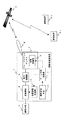
以下、この発明の実施の形態1について図1及び図4を用いて説明する。図1は実施形態1による移動体通信装置の構成等を示すブロック図、図2は図1に示す変復調部5の具体的構成を示す部分ブロック図、図3は図1に示す移動体装置1を搭載した移動体の例を示す移動体概要図である。図1に示すように、この実施の形態1による移動体通信装置は、通信衛星2を介して他の通信装置3a等と通信を行う。図1において、1は航空機、車両等の移動体に搭載する移動体通信装置、2は静止衛星、周回衛星等の通信衛星、3a,3bは他の通信装置であり、図3において、13は移動体装置1を搭載した航空機である。なお、通信衛星2としては、静止軌道上を移動する静止衛星に限らず、低高度の周回軌道上を周回する周回衛星、その他準天頂衛星等を利用することできる。他の通信装置3a,3bとしては、移動体通信装置に限らず、パラボラアンテナ等を用いた固定の通信装置であってもよく、衛星通信が可能に構成された通信装置全般を対象とするものである。
また、図1において、4は音声信号やデータ信号等の衛星に送信する通信信号を出力する通信手段、5は複数の変復調処理部を有する可変レートモデム等の変復調部、6は変復調部5から出力された変調信号を所定の信号レベルまで増幅して出力する増幅部、7はフェーズドアレイアンテナ等の電子走査型のアンテナであって、アンテナビームを指向して増幅部6から出力された変調信号を送信するアンテナ部、8はアンテナ部7のアンテナ素子より構成された送受信面上に形成されたアンテナビーム、9はアンテナ素子の位相量を調節してアンテナビーム8を所定の方向に指向させる位相制御部、10は移動体通信装置1が搭載された移動体の位置、姿勢等の状態を検出する慣性航法装置等の状態検出部、11は状態検出部から出力された移動体の位置情報及び姿勢情報からアンテナビーム8を通信衛星2に指向させる方向を検出し、その指向方向に応じた位相情報を位相制御部9に出力するビーム方向検出部、12はビーム方向検出部11より検出されたアンテナビーム8の指向方向に応じて変復調部5に設けられた変調処理部を切り換える伝送速度制御部である。
In FIG. 1, 4 is a communication means for outputting a communication signal to be transmitted to a satellite such as an audio signal and a data signal, 5 is a modulation / demodulation unit such as a variable rate modem having a plurality of modulation / demodulation processing units, and 6 is a modulation /
なお、図1においては、移動体の位置、姿勢等を検出する状態検出部10を移動体通信装置1内に設けているが、大型の航空機等の場合は、慣性航法装置等の移動体の位置等を検出する手段を別に設けている場合があり、その場合は、別に設けられた状態検出部から移動体の位置情報及び姿勢情報を取得すればよく、移動体通信装置1内に状態検出部を設ける必要はない。ビーム方向検出部11はそのような別に設けられた状態検出部から出力された移動体の位置情報及び姿勢情報からアンテナビーム8を通信衛星2に指向させる方向を検出することができる。
In FIG. 1, a
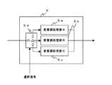
また、図2において、5aは高速の伝送速度に設定された変復調処理部、5bは中速の伝送速度に設定された変復調処理部、5cは低速の伝送速度に設定された変復調処理部、5dは変復調部5に設けられた変復調処理部5a乃至5cの中からいずれかの変復調処理部を選択する選択手段である。実施の形態1では3つの変復調処理部を設けるものについて説明するが、2つの場合でも4つの場合でもよく、これに限られるものではない。なお、実施の形態1では選択手段5dを用いて複数の変復調処理部からいずれか1つの変復調処理部を選択する構成としたが、伝送速度を可変にできる1つの変復調処理部を設け、断続的又は連続的に伝送速度を切り換えるように構成してもよい。
In FIG. 2, 5a is a modulation / demodulation processing unit set to a high transmission rate, 5b is a modulation / demodulation processing unit set to a medium transmission rate, 5c is a modulation / demodulation processing unit set to a low transmission rate, and 5d. Is a selection means for selecting any modulation / demodulation processing unit from among the modulation / demodulation processing units 5a to 5c provided in the modulation /
次に動作について説明する。移動体通信装置1の利用者は、図3に示すような移動体13によって移動しながら他の通信装置3a,3b等との通信を行う。図3において、13aは航空機13のアンテナ搭載位置を示しており、移動体の種類、形等に応じて適宜適当な箇所に移動体通信装置1のアンテナ部7を配置する。なお、図3では移動体装置1を搭載する移動体の例として航空機13を示したが、自動車等の車両に搭載しても同様に通信することができるものである。
Next, the operation will be described. The user of the
まず、通信手段4は、音声信号やデータ信号等の衛星に送信する通信信号を出力する。変復調部5は、通信手段4から出力された通信信号に所定の変調処理を施して変調信号を出力する。具体的には、予め設けられた複数の変復調処理部のうち伝送速度制御部12によって選択された変復調処理部によって通信信号に変調処理を施して変調信号を出力する。変復調部5に設けられた各変復調処理部はそれぞれ異なる伝送レート、すなわち伝送速度が設定されており、変復調部5は各変調処理部に応じた伝送速度の変調信号を出力する。増幅部6は、変復調部5から出力された変調信号を所定のレベルまで増幅処理してアンテナ部7に出力する。
First, the communication unit 4 outputs a communication signal to be transmitted to the satellite such as an audio signal or a data signal. The
アンテナ部7は、位相制御部9によりアンテナ素子の位相量が調節され、通信衛星2の方向を指向するようにアンテナビーム8を形成し、増幅部6において増幅した変調信号を送信信号として通信衛星2に送信する。位相制御部9は、ビーム方向検出部11から出力された位相情報に基づいてアンテナ素子の位相量を調節する。ビーム方向検出部11は、状態検出部10において検出された移動体の位置情報及び姿勢情報等から通信衛星2にアンテナビーム8を指向させる方向を算出し、その方向にアンテナビーム8を指向させるための位相情報を位相制御部9に出力する。なお、状態検出部10は、例えば、移動体に搭載された慣性航法装置(Inertial Navigation System:INS)等であり、この状態検出部10により移動体通信装置1が搭載された移動体の位置、姿勢(バンク角度、ピッチ角度)、速度、進行方向等を検出する。
The antenna unit 7 adjusts the phase amount of the antenna element by the phase control unit 9, forms an
また、アンテナビーム8を通信衛星2に指向させるためには、移動体の位置情報等だけでなく通信衛星2の位置情報も把握しておく必要があるが、通信衛星2が静止衛星の場合は通信衛星2の位置が変化しないので、ビーム方向検出部11は、予め記憶部等に記憶した静止衛星の位置情報と移動体通信装置1が搭載された移動体の位置情報及び姿勢情報からアンテナビーム8を指向させる方向を検出する。なお、通信衛星2が周回衛星等の場合は、通信衛星の位置が常に変化するため、対応する周回衛星の周回情報を予め記憶部に記憶しておき、そのよう周回衛星の現在位置と移動体通信装置1が搭載された移動体の位置情報及び姿勢情報からアンテナビーム8を指向させる方向を検出する。
In addition, in order to direct the
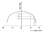
最後に、伝送速度制御部12の動作について図4を用いて詳細に説明する。図4はアンテナビーム8の指向方向とその走査利得との関係を示すデータテーブルであって、例えば、伝送速度制御部12の記憶手段(図示省略する。)に設けられた変換テーブルの例を示す変換テーブル説明図である。図4において、0°がアンテナ部7の送受信面の法線方向であり、横軸は法線方向からのアンテナビーム8の傾き(ビーム角度)、縦軸はアンテナビーム8のビーム角度、すなわちアンテナビーム8の指向方向に対するアンテナ部7の走査利得を示す。図4に示すように、アンテナビーム8が法線方向から傾くほど走査利得は低下する。なお、Raはアンテナビーム8の指向方向が45°の場合における走査利得、Rbはアンテナビーム8の指向方向が60°付近の場合における走査利得、Rcはアンテナビーム8の指向方向が70°付近の場合における走査利得である。
Finally, the operation of the transmission rate control unit 12 will be described in detail with reference to FIG. FIG. 4 is a data table showing the relationship between the directivity direction of the
伝送速度制御部12は、ビーム方向検出部11より検出されたアンテナビーム8の指向方向と図4に示すような変換テーブルとからアンテナ部7の走査利得を求め、その走査利得に応じた選択信号により変復調部5の切換手段5dを切り換える。例えば、走査利得がRa以上の場合は高速の変復調処理部5A、Ra〜Rbの間の場合は中速の変復調処理部5B、Rb〜Rcの間の場合は低速の変復調処理部5Cをそれぞれ選択するように変復調部5の切換手段5dを制御する。このように、伝送速度制御部12によって通信信号に変調処理を施す変復調処理部が切り換えられ、切り換えられた変復調処理部により変調処理を施した通信信号が変調信号として増幅部6に出力される。なお、走査利得がRc以下の場合には、通信継続が困難な状態であり、通信継続が困難であることを表示部(図示省略する。)に表示するようにしてもよい。
The transmission rate control unit 12 obtains the scanning gain of the antenna unit 7 from the directivity direction of the
例えば、移動体通信装置1を搭載した移動体の位置又は姿勢が変化し、アンテナビーム8の指向方向を別の方向に変更する場合、ビーム方向検出部11が状態検出部10からの位置情報及び姿勢情報に基づいてアンテナビーム8を通信衛星2に指向させる方向を検出し、そのアンテナビームの指向方向の情報が伝送速度制御部12に出力される。伝送速度制御部12は、ビーム方向検出部11から出力されたアンテナビームの指向方向の情報と記憶部に予め記憶した変換テーブルとから、ビーム方向検出部11により検出された方向にアンテナビーム8を指向させた場合の走査利得を求め、この走査利得に応じた伝送速度の変復調処理部によって通信信号の変復調処理を施すよう変復調部5の切換手段5dを切り換える。変復調部5は切換手段5dにより変復調処理部が切り換えられると、切り換えた後の変復調処理部によって通信手段4から出力された通信信号に変調処理を施して変調信号を出力する。
For example, when the position or posture of the mobile body on which the
以上のように、実施の形態1による移動体通信装置では、移動体通信装置1を搭載した移動体の位置又は姿勢が変化し、アンテナビーム8の指向方向を別の方向に変更する場合に、ビーム方向検出部11においてアンテナビームを通信衛星2に指向させる方向を検出し、その情報と予め記憶した変換テーブルとからビーム方向検出部11により検出された方向にアンテナビーム8を指向させた場合の走査利得を求め、この走査利得に応じた伝送速度の変復調処理部によって通信信号の変復調処理を施すよう変復調部5の変復調処理部を切り換えるので、移動体の位置や姿勢が変化し、アンテナビームの走査利得の変化に応じて送信信号のC/Nが変化したとしても、C/Nの値に応じた最適な伝送速度を選択することができ、通信衛星を介した効率的かつ確実な通信を行うことができる。
As described above, in the mobile communication device according to the first embodiment, when the position or posture of the mobile body on which the
実施の形態2.
以下、この発明の実施の形態2について説明する。実施の形態1では、通信衛星2が静止衛星の場合を例に説明したが、日本のような高緯度地域においては静止衛星が低仰角方向に位置するため、アンテナ部7の送受信面を地上と平行に配置した場合にはアンテナビーム8の指向方向がほぼ低仰角方向となる。一般にC/Nが高くなる程、伝送速度を高くできるため、電子走査型のアンテナを用いる場合では、送受信面の法線方向にアンテナビームを指向させて通信衛星に送信信号を送信することが望ましい。そこで、実施の形態2では、アンテナビームの指向方向が送受信面のほぼ法線方向となる移動体通信装置について説明する。
The second embodiment of the present invention will be described below. In the first embodiment, the case where the
具体的には、通信衛星2として日本の天頂方向付近を移動する準天頂衛星を使用するものである。準天頂衛星システムは、複数の通信衛星から構成される通信衛星の少なくとも1機が常時日本の天頂方向付近に位置するように配置する衛星システムであり、送信信号を送信する通信衛星2はほぼ真上に位置することから、地上と平行にアンテナ部7の送受信面を配置することによりアンテナビーム8をほぼアンテナ部8の送受信面の法線方向に指向させることができる。
Specifically, a quasi-zenith satellite that moves near the zenith direction in Japan is used as the
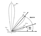
図5は、図1に示すような衛星システムにおいて、準天頂衛星を通信衛星2とした場合と静止衛星を通信衛星2とした場合とのそれぞれのアンテナビーム8の指向方向について比較した比較説明図である。図5において、7bはアンテナ部7の送受信面、8aは送受信面7bの法線方向に形成されたアンテナビーム、8jは準天頂衛星を通信衛星2とした場合の最低仰角方向に形成されたアンテナビーム、8sは静止衛星を通信衛星2とした場合の最低仰角方向に形成されたアンテナビームである。
FIG. 5 is a comparative explanatory diagram comparing the directivity directions of the
図5に示すように、準天頂衛星を通信衛星2とした場合は、最低仰角の角度が高仰角となるので、変復調部5に設けた複数の変復調処理部のうち、高速の伝送速度に設定された変復調処理部により変調処理を施すことができ、通信信号の高速伝送を実現することができる。また、移動体の姿勢(バンク角度、ピッチ角度)を大きくすることができるので、移動体の運用制限にも余裕を持たせることができる。なお、実施の形態2では、本発明に係る移動体通信装置を国内及びその周辺地域において使用する場合、いわゆる準天頂衛星について説明したが、海外の地域で使用する場合も同様であり、図1に示すような移動体通信装置1を使用する地域の天頂方向付近を移動する準天頂衛星と同様な通信衛星を用いる衛星システムに適用しても同様の効果を得ることができる。
As shown in FIG. 5, when the quasi-zenith satellite is the
1 移動体通信装置、2 通信衛星、3 他の通信装置、4 通信手段、
5 変復調部、5a 変復調処理部A、5b 変復調処理部B、
5c 変復調処理部C、6 増幅部、7 アンテナ部、7b 送受信面、
8 アンテナビーム、9 位相制御部、10 状態検出部、11 ビーム方向検出部、
12 伝送速度制御部、13 移動体。
1 mobile communication device, 2 communication satellite, 3 other communication device, 4 communication means,
5 modulation / demodulation unit, 5a modulation / demodulation processing unit A, 5b modulation / demodulation processing unit B,
5c modulation / demodulation processing unit C, 6 amplification unit, 7 antenna unit, 7b transmission / reception surface,
8 antenna beam, 9 phase controller, 10 state detector, 11 beam direction detector,
12 Transmission rate control unit, 13 Mobile.
Claims (4)
The mobile communication device according to claim 1, wherein the satellite is a quasi-zenith satellite that moves in the vicinity of the zenith direction in Japan.
Priority Applications (1)
| Application Number | Priority Date | Filing Date | Title |
|---|---|---|---|
| JP2004105678A JP4222245B2 (en) | 2004-03-31 | 2004-03-31 | Mobile communication device |
Applications Claiming Priority (1)
| Application Number | Priority Date | Filing Date | Title |
|---|---|---|---|
| JP2004105678A JP4222245B2 (en) | 2004-03-31 | 2004-03-31 | Mobile communication device |
Publications (2)
| Publication Number | Publication Date |
|---|---|
| JP2005295094A true JP2005295094A (en) | 2005-10-20 |
| JP4222245B2 JP4222245B2 (en) | 2009-02-12 |
Family
ID=35327565
Family Applications (1)
| Application Number | Title | Priority Date | Filing Date |
|---|---|---|---|
| JP2004105678A Expired - Fee Related JP4222245B2 (en) | 2004-03-31 | 2004-03-31 | Mobile communication device |
Country Status (1)
| Country | Link |
|---|---|
| JP (1) | JP4222245B2 (en) |
Cited By (9)
| Publication number | Priority date | Publication date | Assignee | Title |
|---|---|---|---|---|
| GB2443463A (en) * | 2006-11-03 | 2008-05-07 | Vodafone Plc | Adjusting the size/shape of a radiation beam in dependence on the position of a user terminal in aerospace |
| JP2008278004A (en) * | 2007-04-26 | 2008-11-13 | Mitsubishi Electric Corp | Mobile satellite communication system |
| JP2009071497A (en) * | 2007-09-12 | 2009-04-02 | Oki Electric Ind Co Ltd | Radio communication apparatus |
| CN101858747A (en) * | 2010-03-26 | 2010-10-13 | 航天东方红卫星有限公司 | An Analytical Determination Method of the Attitude of the Satellite Sailboard to the Sun Orientation Target Using the Earth's Irradiation Energy Effectively |
| JP2011083040A (en) * | 2011-01-26 | 2011-04-21 | Mitsubishi Electric Corp | Helicopter satellite communication system and helicopter-mounted communication device employed therefor |
| JP2014187489A (en) * | 2013-03-22 | 2014-10-02 | Furuno Electric Co Ltd | Diversity receiver, diversity reception method and diversity reception program |
| JP2018085687A (en) * | 2016-11-25 | 2018-05-31 | 株式会社東芝 | Satellite communication apparatus and communication method thereof |
| CN112740059A (en) * | 2018-09-26 | 2021-04-30 | 京瓷株式会社 | Electronic device, control method for electronic device, and control program for electronic device |
| JP2022551503A (en) * | 2019-10-11 | 2022-12-09 | 大唐移▲動▼通信▲設▼▲備▼有限公司 | Terminal network access method, device, electronic device and storage medium |
-
2004
- 2004-03-31 JP JP2004105678A patent/JP4222245B2/en not_active Expired - Fee Related
Cited By (12)
| Publication number | Priority date | Publication date | Assignee | Title |
|---|---|---|---|---|
| GB2443463A (en) * | 2006-11-03 | 2008-05-07 | Vodafone Plc | Adjusting the size/shape of a radiation beam in dependence on the position of a user terminal in aerospace |
| GB2443463B (en) * | 2006-11-03 | 2010-12-08 | Vodafone Plc | Mobile telecommunications |
| JP2008278004A (en) * | 2007-04-26 | 2008-11-13 | Mitsubishi Electric Corp | Mobile satellite communication system |
| JP2009071497A (en) * | 2007-09-12 | 2009-04-02 | Oki Electric Ind Co Ltd | Radio communication apparatus |
| CN101858747A (en) * | 2010-03-26 | 2010-10-13 | 航天东方红卫星有限公司 | An Analytical Determination Method of the Attitude of the Satellite Sailboard to the Sun Orientation Target Using the Earth's Irradiation Energy Effectively |
| JP2011083040A (en) * | 2011-01-26 | 2011-04-21 | Mitsubishi Electric Corp | Helicopter satellite communication system and helicopter-mounted communication device employed therefor |
| JP2014187489A (en) * | 2013-03-22 | 2014-10-02 | Furuno Electric Co Ltd | Diversity receiver, diversity reception method and diversity reception program |
| JP2018085687A (en) * | 2016-11-25 | 2018-05-31 | 株式会社東芝 | Satellite communication apparatus and communication method thereof |
| CN112740059A (en) * | 2018-09-26 | 2021-04-30 | 京瓷株式会社 | Electronic device, control method for electronic device, and control program for electronic device |
| JP2022551503A (en) * | 2019-10-11 | 2022-12-09 | 大唐移▲動▼通信▲設▼▲備▼有限公司 | Terminal network access method, device, electronic device and storage medium |
| JP7379687B2 (en) | 2019-10-11 | 2023-11-14 | 大唐移▲動▼通信▲設▼▲備▼有限公司 | Terminal network access methods, devices, electronic devices and storage media |
| US12261681B2 (en) | 2019-10-11 | 2025-03-25 | Datang Mobile Communications Equipment Co., Ltd. | Network access method and apparatus for terminal, electronic device and storage medium |
Also Published As
| Publication number | Publication date |
|---|---|
| JP4222245B2 (en) | 2009-02-12 |
Similar Documents
| Publication | Publication Date | Title |
|---|---|---|
| US12107318B2 (en) | Device and method for reducing interference with adjacent satellites using a mechanically gimbaled asymmetrical-aperture antenna | |
| CN106954223B (en) | Communication method of communication-in-motion end station system and communication-in-motion end station system | |
| JP2019165459A (en) | Architecture for simultaneous spectrum usage by air-to-ground and terrestrial networks | |
| WO2012036896A1 (en) | System and method for dual-band antenna pointing, acquisition, and tracking | |
| EP1180855A1 (en) | Location based adaptive antenna scheme for wireless data applications | |
| JP2006333069A (en) | Antenna control apparatus for mobile body and antenna control method | |
| KR102613223B1 (en) | Low earth orbit satellite signal transmitting/receiving system and method containing hemisphere type antenna | |
| US8144067B2 (en) | Combination planar and parabolic reflector antenna to access satellite | |
| JP4222245B2 (en) | Mobile communication device | |
| JP2006333068A (en) | Antenna tracking device for mobile terminal and antenna tracking method for mobile terminal | |
| WO2020162817A1 (en) | An antenna terminal, a rotatable antenna platform and methods for maritime use | |
| EP3934129B1 (en) | Pointing unit | |
| EP4213408A1 (en) | Satellite receiver with dynamically selected switched antenna elements | |
| KR100392253B1 (en) | Mobile Active Antenna System and its Tracking Method for Multi-satellite signal reception | |
| KR102243296B1 (en) | Antenna operation control apparatus according to link margins in system using of dual antenna and method thereof | |
| CN117999745A (en) | System and method for initial positioning of electronically steerable antennas | |
| EP4213407A1 (en) | Dynamic selection of satellite attitude based on utilization or availability of terrestrial wireless communication network | |
| US11838098B2 (en) | Satellite communication system with high-ground elevation angle | |
| JP3122579U (en) | Antenna tracking device and antenna | |
| JPH0964800A (en) | Mobile SNG device | |
| JPH04307803A (en) | Antenna automatic tracking device | |
| JP2022135374A (en) | Mobile body | |
| JP4882815B2 (en) | Mobile communication device | |
| JPH09162627A (en) | Satellite communication antenna | |
| JPH05167486A (en) | Transmitter-receiver at earth station for satellite communication |
Legal Events
| Date | Code | Title | Description |
|---|---|---|---|
| A621 | Written request for application examination |
Free format text: JAPANESE INTERMEDIATE CODE: A621 Effective date: 20060119 |
|
| A977 | Report on retrieval |
Free format text: JAPANESE INTERMEDIATE CODE: A971007 Effective date: 20080115 |
|
| A131 | Notification of reasons for refusal |
Free format text: JAPANESE INTERMEDIATE CODE: A131 Effective date: 20080122 |
|
| A521 | Written amendment |
Free format text: JAPANESE INTERMEDIATE CODE: A523 Effective date: 20080320 |
|
| TRDD | Decision of grant or rejection written | ||
| A01 | Written decision to grant a patent or to grant a registration (utility model) |
Free format text: JAPANESE INTERMEDIATE CODE: A01 Effective date: 20081028 |
|
| A01 | Written decision to grant a patent or to grant a registration (utility model) |
Free format text: JAPANESE INTERMEDIATE CODE: A01 |
|
| A61 | First payment of annual fees (during grant procedure) |
Free format text: JAPANESE INTERMEDIATE CODE: A61 Effective date: 20081110 |
|
| FPAY | Renewal fee payment (prs date is renewal date of database) |
Free format text: PAYMENT UNTIL: 20111128 Year of fee payment: 3 |
|
| LAPS | Cancellation because of no payment of annual fees |