JP2005295090A - Satellite communication system and satellite communication apparatus - Google Patents
Satellite communication system and satellite communication apparatus Download PDFInfo
- Publication number
- JP2005295090A JP2005295090A JP2004105671A JP2004105671A JP2005295090A JP 2005295090 A JP2005295090 A JP 2005295090A JP 2004105671 A JP2004105671 A JP 2004105671A JP 2004105671 A JP2004105671 A JP 2004105671A JP 2005295090 A JP2005295090 A JP 2005295090A
- Authority
- JP
- Japan
- Prior art keywords
- csc
- line
- satellite
- communication
- uplink
- Prior art date
- Legal status (The legal status is an assumption and is not a legal conclusion. Google has not performed a legal analysis and makes no representation as to the accuracy of the status listed.)
- Withdrawn
Links
Images


Landscapes
- Radio Relay Systems (AREA)
- Mobile Radio Communication Systems (AREA)
Abstract
Description
本発明は、少なくとも一つの親局と複数の子局とを備えた衛星通信システムにおいて、子局が親局に対して上りCSC回線を用いて回線割当要求を送信し、親局が子局に対して下りCSC回線を用いて通信回線の割り当てを制御する衛星通信システムに関する。 The present invention provides a satellite communication system including at least one master station and a plurality of slave stations, wherein the slave station transmits a line allocation request to the master station using an uplink CSC line, and the master station transmits to the slave station. The present invention relates to a satellite communication system that controls assignment of communication lines using a downlink CSC line.
従来の要求時割当多元接続方式(DAMA方式)による衛星通信システムにおいては、子局は通信の都度、親局に対して上りCSC回線による回線割当要求を送信し、それを受信した親局は下りCSC回線による通信回線の割り当て制御を行う。子局は親局により割り当てられた通信回線による通信が終了すると、速やかにその旨を親局に対して通知し、割り当てられた通信回線を開放する。 In a satellite communication system using a conventional multiple access system upon request allocation (DAMA system), a slave station transmits a channel allocation request using an uplink CSC line to the master station each time communication is performed. The communication line assignment control is performed by the CSC line. When the communication via the communication line assigned by the master station is completed, the slave station promptly notifies the master station to that effect and releases the assigned communication line.
また、特許文献1には、位置情報に基づき通信を行うチャンネルを割り当てる衛星通信システムが記載されている。
従来の衛星通信システムにおいては、通信衛星からのシングルビーム又はマルチビームによるサービスエリアの全体に対し共通の上り及び下りCSC回線を設けるため、サービスエリア内の特定地域において子局からの回線割当要求が大量に発生した場合には、それによってサービスエリア全体における上り及び/又は下りCSC回線の輻輳状態が発生し、同一サービスエリア内のその他の地域に存在する子局におけるCSC回線による通信が困難となる。 In a conventional satellite communication system, a common uplink and downlink CSC line is provided for the entire service area of a single beam or multi-beam from a communication satellite, so that a line allocation request from a slave station is made in a specific area within the service area. When a large number of such errors occur, the congestion state of the upstream and / or downstream CSC lines in the entire service area occurs, and it becomes difficult to communicate with the CSC lines in the slave stations existing in other areas in the same service area. .
本発明はこのような事情に鑑みてなされたものであり、通信衛星からのシングルビーム又はマルチビームによるサービスエリアの一部の地域においてCSC回線の輻輳が生じた場合であっても、その輻輳が同じサービスエリア内の他の地域における上り及び/又は下りCSC回線の送受信に影響し難い衛星通信システムを提供することを目的とする。 The present invention has been made in view of such circumstances, and even when the CSC line is congested in a part of the service area of the single beam or multi-beam from the communication satellite, the congestion is not caused. It is an object of the present invention to provide a satellite communication system that is unlikely to affect transmission and reception of uplink and / or downlink CSC lines in other areas within the same service area.
本発明による衛星通信システムにおいては、通信衛星からのシングルビームによるサービスエリアを複数のサブエリアに分割し、それら複数のサブエリアの少なくとも二つのサブエリアの各々に諸元値の異なる上り及び/又は下りCSC回線を個別に設け、子局は自己位置を検出する自己位置検出手段と、自己位置検出手段の検出結果に基づきその位置における上り及び/又は下りCSC回線の諸元値を決定するCSC回線諸元値判定手段と、CSC回線諸元値判定手段により決定された諸元値による上り及び/又は下りCSC回線を用いて親局との通信回線割当に係る送受信を行う送受信手段とを備える。 In the satellite communication system according to the present invention, the service area by a single beam from the communication satellite is divided into a plurality of subareas, and at least two subareas of the plurality of subareas have uplink and / or different specification values. A downlink CSC line is provided separately, and the slave station detects self-position detecting means for detecting its own position, and a CSC line for determining the specification values of the uplink and / or downlink CSC lines at the position based on the detection result of the self-position detecting means. And a transmission / reception unit for performing transmission / reception related to communication line allocation with a master station using an uplink and / or a downlink CSC line based on the specification value determined by the CSC line specification value determination unit.
また、本発明による衛星通信システムにおいては、通信衛星からのマルチビームを構成する複数のビームの少なくとも二つのビームの各々に諸元値の異なる上り及び/又はCSC回線を個別に設け、子局は自己位置を検出する自己位置検出手段と、自己位置検出手段の検出結果に基づきその位置における上り及び/又は下りCSC回線の諸元値を決定するCSC回線諸元値判定手段と、CSC回線諸元値判定手段により決定された諸元値による上り及び/又は下りCSC回線を用いて親局との通信回線割当に係る送受信を行う送受信手段とを備える。 Further, in the satellite communication system according to the present invention, each of at least two beams of a plurality of beams constituting a multi-beam from the communication satellite is individually provided with upstream and / or CSC lines having different specification values, Self-position detecting means for detecting the self-position, CSC line specification value determining means for determining the specification value of the uplink and / or downlink CSC line at the position based on the detection result of the self-position detecting means, and the CSC line specification Transmission / reception means for performing transmission / reception related to communication line allocation with the master station using the uplink and / or downlink CSC lines based on the specification values determined by the value determination means.
本発明における衛星通信システムにおいては、通信衛星からのシングルビームによるサービスエリアを複数のサブエリアに分割し、それら複数のサブエリアの少なくとも二つのサブエリアの各々に諸元値の異なる上り及び/又は下りCSC回線を個別に設ける。これにより、サービスエリア内の特定地域に起因するCSC回線の輻輳が、同一サービスエリア内の他の地域のCSC回線による送受信に与える影響を抑制することができる。 In the satellite communication system according to the present invention, a service area by a single beam from a communication satellite is divided into a plurality of subareas, and at least two subareas of the plurality of subareas have uplink and / or different specification values. A downstream CSC line is provided individually. Thereby, it is possible to suppress the influence of the congestion of the CSC line caused by the specific area in the service area on the transmission / reception by the CSC line in another area in the same service area.
また、本発明における衛星通信システムにおいては、通信衛星からのマルチビームを構成する複数のビームの少なくとも二つのビームの各々に諸元値の異なる上り及び/又はCSC回線を個別に設ける。これによりサービスエリア内の特定地域に起因するCSC回線の輻輳が、同一サービスエリア内の他の地域のCSC回線の送受信に与える影響を抑制することができる。 In the satellite communication system according to the present invention, an uplink and / or CSC line having different specification values is individually provided for each of at least two beams of a plurality of beams constituting a multi-beam from the communication satellite. As a result, the influence of CSC line congestion caused by a specific area in the service area on transmission / reception of CSC lines in other areas in the same service area can be suppressed.
実施の形態1.
本実施の形態1においては、通信衛星からのシングルビームによるサービスエリアを複数のサブエリアに分割し、それら複数のサブエリアの各々に個別に上り及び/又は下りCSC回線を設けることにより、サービスエリア内の特定地域における上り及び/又は下りCSC回線の輻輳が、同一サービスエリア内の他の地域におけるCSC回線の送受信に与える影響を抑制する。
In the first embodiment, a service area by a single beam from a communication satellite is divided into a plurality of subareas, and an uplink and / or a downlink CSC line is individually provided in each of the plurality of subareas. The influence of the congestion of the upstream and / or downstream CSC line in a specific area within the area on the transmission / reception of the CSC line in another area within the same service area is suppressed.
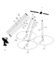
図1は本実施の形態1による衛星通信システムを例示する構成図である。図において、1は通信衛星、2a〜2cの各々は通信衛星1からのシングルビーム(不図示)によるサービスエリアを分割してなるサブエリア、3a〜3cはそれぞれサブエリア2a〜2c内に位置する子局、4a〜4cはそれぞれサブエリア2a〜2cに設けられる上りCSC回線、5a〜5cはそれぞれサブエリア2a〜2cに設けられる下りCSC回線である。これら上りCSC回線4a〜4c及び下りCSC回線5a〜5cのそれぞれは、通信衛星1に搭載されるトランスポンダ(不図示)を介して親局6に接続される。
FIG. 1 is a configuration diagram illustrating a satellite communication system according to the first embodiment. In the figure, 1 is a communication satellite, 2a to 2c are subareas obtained by dividing a service area by a single beam (not shown) from the
ここでCSC回線は、親局と子局との間で回線制御のための通信を行うための回線であり、共通線信号回線とも呼ばれる。子局から親局へのCSC回線は上りCSC回線と呼ばれ、親局から子局へのCSC回線は下りCSC回線と呼ばれる。上りCSC回線においては、子局が親局に対して通信回線の割り当てを要求するための回線割当要求等が送信さる。また、下りCSC回線においては、親局が子局に対して通信回線の割当制御を行うための制御信号が送信される。子局はCSC回線により回線制御を受ける局であり、親局はCSC回線により子局の回線制御を行う局である。 Here, the CSC line is a line for performing communication for line control between the master station and the slave station, and is also called a common line signal line. The CSC line from the slave station to the master station is called an uplink CSC line, and the CSC line from the master station to the slave station is called a downlink CSC line. In the uplink CSC line, a line assignment request for the slave station to request communication line assignment to the master station is transmitted. In the downlink CSC channel, a control signal for the master station to perform communication channel allocation control to the slave station is transmitted. The slave station is a station that receives line control via the CSC line, and the master station is a station that performs line control of the slave station via the CSC line.
親局は子局からの上りCSC回線による回線割当要求を受信して、当該子局と親局との間、当該子局とその他の子局との間、または当該子局と親局に接続されたその他の通信端未との間、などに音声やデータなどを送受信するための通信回線(不図示)を割り当てる。子局はその割当られた通信回線による通信が終了すると、速やかにその旨を親局に対して通知し、割り当てられた通信回線を開放する。 The master station receives a line allocation request from the slave station via the uplink CSC line, and connects between the slave station and the master station, between the slave station and another slave station, or between the slave station and the master station. A communication line (not shown) for transmitting and receiving voice, data, etc. is assigned to the other communication end that has been made. When the communication via the assigned communication line is completed, the slave station immediately notifies the master station to that effect, and releases the assigned communication line.
図1においては、通信衛星1からのシングルビーム(不図示)によるサービスエリアを分割してなるサブエリア2a〜2cの各々に互いに周波数の異なる上りCSC回線4a〜4c、及び/又は、互いに周波数の異なる下りCSC回線5a〜5cが設定される。子局3a〜3cの各々はGPSなどにより自己位置を検出するとともに当該位置における上りCSC回線の諸元値及び/又は下りCSC回線の諸元値を判別し、当該諸元値を有したCSC回線により回線制御に係る信号を送受信する。
In FIG. 1, each of sub-areas 2a to 2c obtained by dividing a service area by a single beam (not shown) from a
なお、上り又は下りCSC回線のいずれかにおいてサブエリア毎に周波数を異ならせない場合には、その異ならせない方のCSC回線については、サービスエリア全体で用いることができるCSC回線を設ければよい。また、子局の位置検出はGPSに限らず、その他どのような位置検出手段であってもよい。 If the frequency is not different for each subarea in either the uplink or downlink CSC line, a CSC line that can be used in the entire service area may be provided for the CSC line that does not differ. . The position detection of the slave station is not limited to GPS, and any other position detection means may be used.
また、ここでのサブエリアへのCSC回線の設定とは、必ずしも当該設定されたCSC回線がサブエリア内でのみ利用可能である場合に限るものではなく、そのCSC回線がサービスエリア全域から利用可能な状態ではあるものの、子局及び/又は親局がそのサブエリア外においてそのCSC回線を利用しないよう設定されている場合も含むものとする。 The setting of the CSC line to the subarea here is not necessarily limited to the case where the set CSC line can be used only within the subarea, and the CSC line can be used from the entire service area. In this state, the case where the slave station and / or the master station is set not to use the CSC line outside the subarea is included.
図2は本実施の形態1による衛星通信システムの上りCSC回線(FDMA)の諸元値を説明する概念図である。図において、図1と同一又は相当部分には同一符号を付して説明を省略する。図示するように、本実施の形態1においては、通信衛星1からのシングルビーム(不図示)によるサービスエリアを分割してなるサブエリア2a〜2cの各々に諸元値(周波数の値)の異なる上りCSC回線を割り当てる。なお、下りCSC回線についても同様にし得る点については既に説明の通りである。
FIG. 2 is a conceptual diagram illustrating specification values of the uplink CSC line (FDMA) of the satellite communication system according to the first embodiment. In the figure, the same or corresponding parts as in FIG. As shown in the figure, in the first embodiment, the specification values (frequency values) are different in each of the sub-areas 2a to 2c obtained by dividing the service area by a single beam (not shown) from the
図3は本実施の形態1による衛星通信システムにおける子局の構成を例示する機能的ブロック図である。図において、図1と同一又は相当部分には同一符号を付して説明を省略する。図において、3は子局、31はGPS等により子局3の現在位置を検出する地上端未位置検出部、32は異なる複数の位置の各々について上り及び/又は下りCSC回線の諸元値についての情報を記憶するCSC諸元値情報記憶部、33は位置検出部31における位置検出結果及びCSC諸元値情報記憶部32の記憶内容に基づき上り及び下りCSC回線の諸元値を決定するCSC諸元値決定部、35はCSC諸元値決定部33が決定した上り及び下りCSC回線の諸元値に対応して変復調を行うCSCモデム、36はアンテナ、37はアンテナ36を介して送受信される信号について増幅や中間周波数への変換・逆変換等を行う送受信部である。
FIG. 3 is a functional block diagram illustrating the configuration of the slave station in the satellite communication system according to the first embodiment. In the figure, the same or corresponding parts as in FIG. In the figure, 3 is a slave station, 31 is a ground-end non-position detecting unit that detects the current position of the
また、38は入力された送信すべき音声やデータを変調して送受信部37へ出力すると共に、送受信部37から入力される変調された音声やデータを復調して出力する通信モデム、39は回線割当要求を生成してCSCモデムへ出力すると共に、CSCモデムを介して入力される回線制御信号に基づき通信モデム38における変復調を制御する通信制御部である。
また、図4は本実施の形態1による衛星通信システムにおける親局を例示する機能的ブロック図である。図において6は親局、61はCSCモデムや通信モデムを備えた送受信部、62はサービスエリア内の各位置における上りCSC回線の諸元値と下りCSC回線の諸元値とを対応づけて記憶するCSC諸元値情報記憶部、63は子局に対する通信回線の割当を制御するための回線割当制御部である。
FIG. 4 is a functional block diagram illustrating a master station in the satellite communication system according to the first embodiment. In the figure, 6 is a master station, 61 is a transmission / reception unit equipped with a CSC modem or communication modem, and 62 is a table that associates the specification values of the upstream CSC line and the specification values of the downstream CSC line at each position in the service area. A CSC specification value
図3及び図4に示した子局3および親局6の動作について説明する。まず、子局3は通信要求が発生した場合、地上端未位置検出部31により自己位置を検出する。次にCSC諸元値決定部33により、当該検出された自己位置およびCSC諸元値情報記憶部32の記憶内容等に基づき上り及び下りCSC回線の諸元値を決定する。上り又は下りCSC回線のいずれかにおいてサブエリア毎に周波数を異ならせない場合には、その異ならせない方のCSC回線については、予め決められたサービスエリア全体で用いられるCSC回線の諸元値が用いられる。次にCSCモデムにおける変復調が当該CSC諸元値決定部により決定されたCSC回線の諸元値に応じて調整される。次に、通信制御部39において回線割当要求が生成され、その回線割当要求がCSCモデム35、送受信部37、およびアンテナ36、通信衛星1を介して親局6へ送信される。
Operations of the
この親局1へ送信された回線割当要求は、親局1の送受信部61を介して回線割当制御部63へ入力される。回線割当制御部63はこの回線割当要求に応答して子局3における通信回線の利用を制御するための回線制御信号を生成するとともに、その回線割当要求が送信されてきた上りCSC回線に対応した下りCSC回線の諸元値をCSC諸元値情報記憶部62に基づき決定する。次に、回線割当制御部63はこの決定された諸元値を有する下りCSC回線を用いて、前記回線制御信号を送信する。
The line assignment request transmitted to the
この親局6から送信された回線制御信号は、子局3においてアンテナ36、送受信部37、CSCモデム35を介して通信制御部39へ入力され、通信制御部39はこの回線制御信号に基づき、通信モデム38を調整する。その後、この通信モデム38を介して音声・データなどが、送受信部37、アンテナ36を介して送受信される。
The line control signal transmitted from the
ここでは、図1及び図2に示した衛星通信システムにおいて、複数のサブエリアの各々に設けられるCSC回線が互いに周波数分割多元接続(FDMA)の関係にある場合について例示したが、これに限るものではなく、時分割多元接続(TDMA)や符号分割多元接続(CDMA)の関係にあるCSC回線を用いてもよい。たとえば、複数のサブエリアの各々に設けられるCSC回線が互いに時分割多元接続(TDMA)の関係にある場合の例について図5に示す。図において、図1と同一又は相当部分については同一符号を付して説明を省略する。 Here, in the satellite communication system shown in FIG. 1 and FIG. 2, the case where the CSC lines provided in each of the plurality of subareas are in a frequency division multiple access (FDMA) relationship with each other is illustrated. Instead, a CSC line having a relationship of time division multiple access (TDMA) or code division multiple access (CDMA) may be used. For example, FIG. 5 shows an example in which CSC lines provided in each of a plurality of subareas are in a time division multiple access (TDMA) relationship. In the figure, the same or corresponding parts as in FIG.
以上のように、本実施の形態1においては、通信衛星からのシングルビームによるサービスエリアを複数のサブエリアに分割し、それら複数のサブエリアの少なくとも二つのサブエリアの各々に諸元値の異なる上り及び/又は下りCSC回線を個別に設け、子局は自己位置に基づき、送受信に用いる上り及び/又は下りCSC回線の諸元値を決定するので、サービスエリア内の特定地域に起因するCSC回線の輻輳が、同一サービスエリア内の他の地域におけるCSC回線の送受信に与える影響を抑制することができる。 As described above, in the first embodiment, a service area by a single beam from a communication satellite is divided into a plurality of subareas, and specification values are different in each of at least two subareas of the plurality of subareas. The uplink and / or downlink CSC lines are individually provided, and the slave station determines the specification values of the uplink and / or downlink CSC lines used for transmission / reception based on its own position, so that the CSC lines caused by a specific area in the service area The influence of the congestion on the transmission / reception of the CSC line in other areas in the same service area can be suppressed.
実施の形態2.
本実施の形態2による衛星通信システムにおいては、通信衛星からのマルチビームを構成する複数のビームの少なくとも二つのビームの各々に諸元値の異なる上り及び/又は下りCSC回線を個別に設けることにより、サービスエリア内の特定地域に起因するCSC回線の輻輳が、同一サービスエリア内の他の地域におけるCSC回線の送受信に与える影響を抑制する。
Embodiment 2. FIG.
In the satellite communication system according to the second embodiment, each of at least two beams of a plurality of beams constituting a multi-beam from a communication satellite is individually provided with an uplink and / or downlink CSC line having different specification values. The influence of CSC line congestion caused by a specific area in the service area on transmission / reception of the CSC line in other areas in the same service area is suppressed.
図6は、マルチビームを構成する複数のビーム21a〜21cの各々にCSC回線として異なるTDMAフレームを割り当てた例を示したものである。図において、図1と同一又は相当部分には同一符号を付して説明を省略する。この場合も、実施の形態1と同様に、子局において自己位置を検出し、その検出結果により上り及び/又は下りCSC回線の諸元値を決定するようにすれば、親局とCSC回線による通信が可能となる。
FIG. 6 shows an example in which different TDMA frames are assigned as CSC lines to the plurality of
以上のように本実施の形態2においては、通信衛星からのマルチビームを構成する複数のビームの少なくとも二つのビームの各々に諸元値の異なる上り及び/又はCSC回線を個別に設け、子局は自己位置に基づき、送受信に用いる上り及び/又は下りCSC回線の諸元値を変化させるので、サービスエリア内の特定地域に起因するCSC回線の輻輳が、同一サービスエリア内の他の地域におけるCSC回線の送受信に与える影響を抑制することができる。 As described above, in the second embodiment, each of at least two beams of a plurality of beams constituting a multi-beam from a communication satellite is individually provided with an uplink and / or CSC line having different specification values, and a slave station Changes the specification values of the uplink and / or downlink CSC lines used for transmission and reception based on the self-location, so that the congestion of the CSC lines caused by a specific area in the service area may cause CSC in other areas in the same service area. The influence on transmission / reception of a line can be suppressed.
実施の形態3.
本発明を準天頂衛星システムに適用した場合について説明する。準天頂衛星システムは、天頂付近を通過する複数の衛星(以下、各々の衛星を準天頂衛星と称す)を順次に切り替えて使用することにより、常時又は長時間に渡って天頂付近からの衛星サービスを提供するものである。以下、準天頂衛星を3機用いて日本付近をサービスエリアとした場合の準天頂衛星システムを例にとり説明する。
A case where the present invention is applied to a quasi-zenith satellite system will be described. The Quasi-Zenith Satellite System is a satellite service from near the zenith at all times or for a long time by switching and using multiple satellites that pass near the zenith (hereinafter each satellite is called the Quasi-Zenith Satellite). Is to provide. Hereinafter, a quasi-zenith satellite system in the case where three quasi-zenith satellites are used and the vicinity of Japan is used as a service area will be described as an example.
3機の準天頂衛星の軌道諸元は、例えば軌道長半径42164km,離心率0.099,軌道傾斜角45度,近地点引数270度,昇交点赤経120度等配とすることができる。但し、この軌道諸元下においては、2箇所の会合点(ペリジ+8H及びペリジ+16H)で2機の準天頂衛星が近接して交差するため、各衛星の軌道保持精度が低い場合には、それら衛星が衝突しないよう、各衛星の軌道保持範囲をずらず必要がある。例えば、上記軌道諸元において3機の各衛星の軌道保持範囲が±0.1度である場合、3機の衛星中、2機の衛星の軌道保持範囲を各衛星の進行方向にそれぞれ +0.36度、-0.36度程度ずらすことにより衝突を防止できる。 The orbital specifications of the three quasi-zenith satellites can be, for example, an orbital length radius of 42164 km, an eccentricity of 0.099, an orbital inclination angle of 45 degrees, a perimeter argument of 270 degrees, an ascending intersection red longitude of 120 degrees. However, under this orbital specification, two quasi-zenith satellites intersect closely at two meeting points (Perigi + 8H and Perigi + 16H). It is necessary to keep the orbit maintenance range of each satellite so that the satellites do not collide. For example, if the orbital holding range of each of the three satellites is ± 0.1 degrees in the above orbital specification, the orbital holding range of the two satellites in the three satellites is +0.36 degrees in the direction of travel of each satellite, Collision can be prevented by shifting about -0.36 degrees.
図7はこのような衝突防止策を施した準天頂衛星軌道の地表面軌跡を例示する概略図である。図中のAは日本から見た天頂付近(例えば、仰角が70度以上となる高仰角領域)であり、3機の準天頂衛星が天頂付近に入れ代わり立ち代り交代で進入し、それぞれ8時間以上のあいだ天頂付近A内に滞留する。このため、天頂付近A内には常に少なくとも1機の準天頂衛星が滞留し、地上端未はそれら3機の衛星を切り替えて使用することにより、常に天頂付近からの衛星サービスを受けることが可能となる。なお、各準天頂衛星の軌道は図7に示す8の字形のものに限らず、涙形のものなど、その他の衛星軌道とすることも可能である。 FIG. 7 is a schematic view illustrating the ground surface trajectory of the quasi-zenith satellite orbit subjected to such a collision prevention measure. A in the figure is the vicinity of the zenith as seen from Japan (for example, the high elevation angle region where the elevation angle is 70 degrees or more). It stays in A near the zenith. For this reason, at least one quasi-zenith satellite always stays in the vicinity of the zenith, and it is possible to always receive satellite services from the vicinity of the zenith by switching and using these three satellites on the ground edge. It becomes. Note that the orbit of each quasi-zenith satellite is not limited to the eight-shaped one shown in FIG. 7, but may be other satellite orbits such as a teardrop-shaped one.
図8は準天頂衛星1機あたりのビームカバレッジを例示したものである。101a〜101eは準天頂衛星からの不図示のマルチビームを構成する複数のビーム、102は準天頂衛星と親局105との間に設けられるスポットビームである。準天頂衛星103は、これらマルチビーム及びスポットビームを介して、マルチビーム内の子局と親局105との間の通信を中継する。
FIG. 8 illustrates the beam coverage per quasi-zenith satellite. 101 a to 101 e are a plurality of beams constituting a multi-beam (not shown) from the quasi-zenith satellite, and 102 is a spot beam provided between the quasi-zenith satellite and the
準天頂衛星は、天頂付近Aに滞留する約8時間以上の間、上述のビームカバレッジが地上に対して移動しないよう姿勢制御される。即ち、準天頂衛星からのマルチビーム101及びスポットビーム102は準天頂衛星が天頂付近に滞留するあいだ、地上に対して固定される。また3機の準天頂衛星の各々が天頂付近Aにおいて形成するビームカバレッジは地上に対して同一である。
The position of the quasi-zenith satellite is controlled so that the above-mentioned beam coverage does not move with respect to the ground for about 8 hours or more staying in the vicinity of the zenith A. That is, the multi-beam 101 and the
本実施の形態3においては、上述のマルチビーム1を構成する複数のビーム1a〜1eの各々に個別に上り及び下りCSC回線を設ける。図9は本実施の形態3による準天頂衛星システムを例示する概略図である。図において、103a〜103cの各々は準天頂衛星である。以下、3機の準天頂衛星103a〜103cの構成が同一で、準天頂衛星103aが天頂付近Aに存在する場合を例にとり説明する。
In the third embodiment, uplink and downlink CSC lines are individually provided for each of the plurality of beams 1a to 1e constituting the multi-beam 1 described above. FIG. 9 is a schematic view illustrating a quasi-zenith satellite system according to the third embodiment. In the figure, each of 103a to 103c is a quasi-zenith satellite. Hereinafter, the case where the three
図9において、101は準天頂衛星103aが形成するマルチビーム、101a〜101eはマルチビーム101を構成する各々のビーム、104は準天頂衛星と通信する機能を有した子局、105は親局、102は準天頂衛星103aと親局105が通信するためのスポットビーム、106は親局105に接続される地上ネットワーク、107は地上ネットワーク106に接続される通信端未である。また、1011a〜1011eはビーム101a〜101eの各々に設けられる上りCSC回線、1012a〜1012eはビーム101a〜101eの各々に設けられる下りCSC回線、1013a〜1013eはビーム101a〜101eの各々に設けられる通信/放送用回線である。ここで、準天頂衛星103aはベントタイプのトランスポンダを備えており、ビーム101a〜101eの各々に設けられた上りCSC回線1011a〜1011e、下りCSC回線1012a〜1012e、及び通信/放送用回線1013a〜1013eの各々は、当該トランスポンダ及びスポットビーム102により親局105へ接続される(不図示)。たとえば、マルチビームはKu帯、スポットビームはKa帯を用いるなど、マルチビームとスポットビームの用いる周波数帯を異ならせることも可能である。
In FIG. 9, 101 is a multi-beam formed by the
図10は図9に示した子局104の構成を例示する概略図である。図において、図3と同一又は相当部分には同一符号を付して説明を省略する。ここでは、CSC諸元値情報記憶部321に、ビーム101a〜101eの配置に対応した各位置におけるCSC回線の諸元値が記憶される。例えば、ビーム単位で利用できるCSC回線の諸元値が異なり、複数のビームが重複する位置においては、その重複するビームのいずれかのCSC回線を用いるように設定される。その他の点においては、基本的に図3に示したものの動作と同様である。なお、複数のビーム101a〜101eのうちの二つ以上が重複する位置において、いずれのビーム101a〜101eのCSC回線を用いるかは、準天頂衛星を介して親局から通知されてくる各CSC回線の混雑状況に基づき決定してもよい。
FIG. 10 is a schematic view illustrating the configuration of the slave station 104 shown in FIG. In the figure, the same or corresponding parts as in FIG. Here, the CSC specification value
また、図11は図9に示した親局の構成を例示する概略図である。図において図4と同一又は相当部分には、同一符号を付して説明を省略する。送受信部61に含まれる通信モデムが地上ネットワーム106を介して接続される通信端未107からのデータを送受信することがある点を除き、基本的に図4に示した親局の構成と同様である。
FIG. 11 is a schematic diagram illustrating the configuration of the master station shown in FIG. In the figure, the same or corresponding parts as in FIG. 4 is basically the same as the configuration of the master station shown in FIG. 4 except that the communication modem included in the transmission /
以上のように、本実施の形態3によれば、準天頂衛星からのマルチビームを構成する複数のビームの各々に対して、諸元値の異なるCSC回線を割り当てたので、首都圏など特定の地域におけるCSC回線の輻輳が、その他の地域における準天頂衛星マルチビームによるCSC回線の送受信に与える影響を抑制することができる。 As described above, according to the third embodiment, a CSC line having a different specification value is assigned to each of a plurality of beams constituting a multi-beam from a quasi-zenith satellite. The influence of the congestion of the CSC line in the region on the transmission / reception of the CSC line by the quasi-zenith satellite multi-beam in other regions can be suppressed.
本発明による衛星通信システムは、子局が子局−親局間の通信に用いるための通信回線の割当要求をCSC回線を用いて親局へ送信する場合のみならず、子局が当該親局以外の装置との通信を行うための通信回線の割当要求を、当該親局に対してCSC回線を用いて行う場合にも利用することができる。 The satellite communication system according to the present invention is not limited to a case where a slave station transmits a communication line assignment request for use in communication between the slave station and the master station to the master station using the CSC line. It is also possible to use a communication line assignment request for performing communication with a device other than the above-mentioned device using the CSC line to the master station.
1 通信衛星、2 サブエリア、3 子局、6 親局、4a〜4c 上りcsc回線、5a〜5c 下りCSC回線。
1 communication satellite, 2 sub-area, 3 slave station, 6 master station, 4a-4c upstream csc line, 5a-5c downstream CSC line.
Claims (5)
自己位置を検出する自己位置検出手段と、自己位置検出手段の検出結果に基づきその位置における上り及び/又は下りCSC回線の諸元値を決定するCSC回線諸元値判定手段と、CSC回線諸元値判定手段により決定された諸元値による上り及び/又は下りCSC回線を用いて親局と通信回線割当に係る送受信を行う送受信手段とを備えたことを特徴とする衛星通信装置。 A satellite in which a service area by a single beam from a communication satellite is divided into a plurality of sub-areas, and at least two sub-areas of the plurality of sub-areas are individually provided with uplink and / or downlink CSC lines having different specification values A satellite communication device used in a communication system,
Self-position detecting means for detecting the self-position, CSC line specification value determining means for determining the specification value of the uplink and / or downlink CSC line at the position based on the detection result of the self-position detecting means, and the CSC line specification A satellite communication apparatus comprising: a transmission / reception means for performing transmission / reception related to communication line allocation with a master station using an uplink and / or downlink CSC line based on a specification value determined by a value determination means.
自己位置を検出する自己位置検出手段と、自己位置検出手段の検出結果に基づきその位置における上り及び/又は下りCSC回線の諸元値を決定するCSC回線諸元値判定手段と、CSC回線諸元値判定手段により決定された諸元値による上り及び/又は下りCSC回線を用いて親局と通信回線割当に係る送受信を行う送受信手段とを備えたことを特徴とする衛星通信装置。 A satellite communication device used in a satellite communication system in which uplink and / or CSC lines having different specification values are individually provided in each of at least two of a plurality of beams constituting a multi-beam from a communication satellite,
Self-position detecting means for detecting the self-position, CSC line specification value determining means for determining the specification value of the uplink and / or downlink CSC line at the position based on the detection result of the self-position detecting means, and the CSC line specification A satellite communication apparatus comprising: a transmission / reception means for performing transmission / reception related to communication line allocation with a master station using an uplink and / or downlink CSC line based on a specification value determined by a value determination means.
A satellite communication system in which uplink and / or downlink CSC lines having different specification values are individually provided in at least two of a plurality of beams constituting a multi-beam from a communication satellite.
Priority Applications (1)
| Application Number | Priority Date | Filing Date | Title |
|---|---|---|---|
| JP2004105671A JP2005295090A (en) | 2004-03-31 | 2004-03-31 | Satellite communication system and satellite communication apparatus |
Applications Claiming Priority (1)
| Application Number | Priority Date | Filing Date | Title |
|---|---|---|---|
| JP2004105671A JP2005295090A (en) | 2004-03-31 | 2004-03-31 | Satellite communication system and satellite communication apparatus |
Publications (1)
| Publication Number | Publication Date |
|---|---|
| JP2005295090A true JP2005295090A (en) | 2005-10-20 |
Family
ID=35327561
Family Applications (1)
| Application Number | Title | Priority Date | Filing Date |
|---|---|---|---|
| JP2004105671A Withdrawn JP2005295090A (en) | 2004-03-31 | 2004-03-31 | Satellite communication system and satellite communication apparatus |
Country Status (1)
| Country | Link |
|---|---|
| JP (1) | JP2005295090A (en) |
Cited By (4)
| Publication number | Priority date | Publication date | Assignee | Title |
|---|---|---|---|---|
| JP2014175765A (en) * | 2013-03-07 | 2014-09-22 | Mitsubishi Electric Corp | Satellite communication system, satellite communication control method, and program |
| WO2019021648A1 (en) * | 2017-07-24 | 2019-01-31 | パナソニックIpマネジメント株式会社 | Transmitter and transmission method |
| JP2019511144A (en) * | 2016-01-28 | 2019-04-18 | クアルコム,インコーポレイテッド | Subdivision of asymmetric forward and reverse links into subframes |
| JP7108737B1 (en) | 2021-04-09 | 2022-07-28 | ソフトバンク株式会社 | COMMUNICATION REPAIR DEVICE, REMOTE CONTROL DEVICE, SYSTEM, AREA CONTROL METHOD AND PROGRAM |
-
2004
- 2004-03-31 JP JP2004105671A patent/JP2005295090A/en not_active Withdrawn
Cited By (9)
| Publication number | Priority date | Publication date | Assignee | Title |
|---|---|---|---|---|
| JP2014175765A (en) * | 2013-03-07 | 2014-09-22 | Mitsubishi Electric Corp | Satellite communication system, satellite communication control method, and program |
| JP2019511144A (en) * | 2016-01-28 | 2019-04-18 | クアルコム,インコーポレイテッド | Subdivision of asymmetric forward and reverse links into subframes |
| WO2019021648A1 (en) * | 2017-07-24 | 2019-01-31 | パナソニックIpマネジメント株式会社 | Transmitter and transmission method |
| JPWO2019021648A1 (en) * | 2017-07-24 | 2020-05-28 | パナソニックIpマネジメント株式会社 | Transmitter and transmission method |
| JP7203357B2 (en) | 2017-07-24 | 2023-01-13 | パナソニックIpマネジメント株式会社 | Transmitter and transmission method |
| JP7108737B1 (en) | 2021-04-09 | 2022-07-28 | ソフトバンク株式会社 | COMMUNICATION REPAIR DEVICE, REMOTE CONTROL DEVICE, SYSTEM, AREA CONTROL METHOD AND PROGRAM |
| WO2022215487A1 (en) * | 2021-04-09 | 2022-10-13 | ソフトバンク株式会社 | Communication relay device, remote control device, system, area control method, and program |
| JP2022161734A (en) * | 2021-04-09 | 2022-10-21 | ソフトバンク株式会社 | Communication relay device, remote control device, system, area control method, and program |
| US12494840B2 (en) | 2021-04-09 | 2025-12-09 | Softbank Corp. | Communication relay apparatus, remote control apparatus, system, area control method and program |
Similar Documents
| Publication | Publication Date | Title |
|---|---|---|
| US11546126B2 (en) | Asymmetric TDD in flexible use spectrum | |
| US8023939B2 (en) | Reusing frequencies of a fixed and/or mobile communications system | |
| US6539200B1 (en) | Method and apparatus for paging a user terminal within the “sweet spot” of a satellite | |
| US7068975B2 (en) | Systems and methods for sharing uplink bandwidth among satellites in a common orbital slot | |
| US8526941B2 (en) | Apparatus and methods for mobility management in hybrid terrestrial-satellite mobile communications systems | |
| US10411362B2 (en) | Synchronization for satellite system | |
| US8520561B2 (en) | Systems, methods and network components that provide different satellite spot beam return carrier groupings and reuse patterns | |
| US6424831B1 (en) | Apparatus and method for paging a user terminal in a satellite communication system | |
| JPH0779187A (en) | Method for covering shadow zone of mobile radio communication cellular system and radio repeater for implementing the same | |
| GB2303764A (en) | Communication with a mobile station in an unknown spot beam | |
| EP2947789A1 (en) | Satellite communication system with time-multiplexed communication from spot beam defined sub-regions | |
| JP4575182B2 (en) | Satellite communication terminal and management station | |
| EP1177644B1 (en) | Method and apparatus for minimizing the number of channels used in paging | |
| US9042809B2 (en) | Satellite communication having distinct low priority information broadcast into adjacent sub-regions | |
| JPH10327103A (en) | Transmission power control method | |
| KR20040029279A (en) | Satellite broadcasting method, and base station and mobile station for use with satellite broadcasting method | |
| JP2004304287A (en) | Satellite communication system, base station and mobile station | |
| WO2001011802A1 (en) | Satellite data system | |
| JPS6322693B2 (en) |
Legal Events
| Date | Code | Title | Description |
|---|---|---|---|
| A621 | Written request for application examination |
Free format text: JAPANESE INTERMEDIATE CODE: A621 Effective date: 20060112 |
|
| A761 | Written withdrawal of application |
Free format text: JAPANESE INTERMEDIATE CODE: A761 Effective date: 20070201 |