JP2005295072A - Arm-mounted radio - Google Patents
Arm-mounted radio Download PDFInfo
- Publication number
- JP2005295072A JP2005295072A JP2004105355A JP2004105355A JP2005295072A JP 2005295072 A JP2005295072 A JP 2005295072A JP 2004105355 A JP2004105355 A JP 2004105355A JP 2004105355 A JP2004105355 A JP 2004105355A JP 2005295072 A JP2005295072 A JP 2005295072A
- Authority
- JP
- Japan
- Prior art keywords
- arm
- communication device
- main body
- antenna unit
- antenna
- Prior art date
- Legal status (The legal status is an assumption and is not a legal conclusion. Google has not performed a legal analysis and makes no representation as to the accuracy of the status listed.)
- Pending
Links
Images

Landscapes
- Details Of Aerials (AREA)
- Support Of Aerials (AREA)
Abstract
【課題】 腕に装着する腕装着型無線機において、製造コストを増加させることなく、容易に取り扱うことができるようにする。
【解決手段】 信号の送受信を行う通信機本体3と、前記通信機本体3を腕Wに装着するための装着体5と、前記通信機本体3の側面3cから突出して設けられたアンテナ部13とを備え、前記アンテナ部13が、前記アンテナ部13の基端側から先端側に行くにしたがい、前記腕Wに接触する前記通信機本体3の裏面3aから離間する方向に延びていることを特徴とする腕装着型無線機1を提供する。
【選択図】 図2PROBLEM TO BE SOLVED: To easily handle an arm-mounted radio device mounted on an arm without increasing the manufacturing cost.
A communication device body 3 for transmitting and receiving signals, a mounting body 5 for mounting the communication device body 3 on an arm W, and an antenna portion 13 provided so as to protrude from a side surface 3c of the communication device body 3. The antenna portion 13 extends in a direction away from the back surface 3a of the communication device main body 3 that contacts the arm W as it goes from the proximal end side to the distal end side of the antenna portion 13. A featured arm-mounted radio device 1 is provided.
[Selection] Figure 2
Description
この発明は、腕に装着する腕装着型無線機に関するものである。 The present invention relates to an arm-mounted radio device mounted on an arm.
近年、腕時計と同様に、腕に装着できる携帯電話機等の無線通信機(腕装着型無線機)がある(例えば、特許文献1参照)。この無線通信機には、電波を送受信するホイップアンテナやヘリカルアンテナが設けられているが、人体や腕時計本体の内部に配された各種電子部品に近接してヘリカルアンテナ等が配される状態においては、アンテナの感度が劣化する。このため、従来では、ヘリカルアンテナ等を通信機本体の上面から垂直に突出させて設けていた。
また、この種の無線通信機としては、装着体により通信機本体を腕に装着した状態においても、アンテナ特性の劣化が少ないパッチアンテナを装着体の内部に設けたものもある(例えば、特許文献2参照。)。
Further, as this type of wireless communication device, there is also a wireless communication device in which a patch antenna with little deterioration in antenna characteristics is provided inside the mounting body even when the communication device body is mounted on the arm by the mounting body (for example, Patent Documents). 2).
しかしながら、特許文献1に記載の無線通信機においては、通信機本体の上面から突出するヘリカルアンテナの突出量が大きいため、この無線通信機を腕に装着した状態において、ヘリカルアンテナが引っ掛かる虞があり、無線通信機の取り扱いが面倒となる問題がある。
また、特許文献2に記載の無線通信機においては、パッチアンテナを装着体の内部に設けているが、パッチアンテナはヘリカルアンテナ等よりも高価であるため、無線通信機の製造コストが増加するという問題がある。
この発明は上述した事情に鑑みてなされたものであって、製造コストを増加させることなく、容易に取り扱うことができる腕装着型無線機を提供することを目的とする。
However, in the wireless communication device described in
In addition, in the wireless communication device described in Patent Document 2, the patch antenna is provided inside the mounting body. However, the patch antenna is more expensive than the helical antenna or the like, so that the manufacturing cost of the wireless communication device increases. There's a problem.
The present invention has been made in view of the above-described circumstances, and an object thereof is to provide an arm-mounted radio device that can be easily handled without increasing the manufacturing cost.
上記目的を達成するために、この発明は以下の手段を提供する。
本発明の腕装着型無線機は、信号の送受信を行う通信機本体と、前記通信機本体を腕に装着するための装着体と、前記通信機本体若しくは前記装着体の側面から突出して設けられたアンテナ部とを備え、前記アンテナ部が、前記アンテナ部の基端側から先端側に行くにしたがい、前記腕に接触する前記通信機本体若しくは前記装着体の裏面から離間する方向に延びていることを特徴とする。
この発明に係る腕装着型無線機によれば、アンテナ部が通信機本体や装着体の側面から突出し、裏面から離間する方向に延びるため、腕装着型無線機を腕に装着した状態において、アンテナ部の先端部が腕から離間した位置に配されることになり、アンテナ部の感度劣化を抑制することができる。
In order to achieve the above object, the present invention provides the following means.
An arm-mounted radio device of the present invention is provided with a communication device main body for transmitting and receiving signals, a mounting body for mounting the communication device main body on an arm, and protruding from a side surface of the communication device main body or the mounting body. The antenna unit extends in a direction away from the back surface of the communication device main body or the mounting body that contacts the arm as the antenna unit goes from the proximal end side to the distal end side of the antenna unit. It is characterized by that.
According to the arm-mounted radio device according to the present invention, the antenna unit protrudes from the side surface of the communication device main body or the mounting body and extends in a direction away from the back surface. The tip of the part is arranged at a position away from the arm, and the sensitivity deterioration of the antenna part can be suppressed.
また、アンテナ部は、通信機本体や装着体から外方に突出する所謂ホイップアンテナやヘリカルアンテナであるため、通信機本体や装着体の内部に設けるパッチアンテナよりも安価となり、腕装着型無線機の製造コストの増加を防止することができる。
また、前記アンテナ部の延出方向が、前記アンテナ部の取付位置に隣接する前記裏面の接線に対して鋭角をなす方向であることを特徴とする。
In addition, the antenna unit is a so-called whip antenna or helical antenna that protrudes outward from the communication device main body or the mounting body, so it is cheaper than the patch antenna provided inside the communication device main body or the mounting body, and the arm-mounted radio device An increase in manufacturing cost can be prevented.
Further, the extending direction of the antenna part is a direction that forms an acute angle with respect to a tangent to the back surface adjacent to the mounting position of the antenna part.
この発明に係る腕装着型無線機によれば、アンテナ部が通信機本体や装着体の裏面の接線に対して傾斜する方向に延びているため、アンテナ部の先端部を確実に前記裏面や腕から離間した位置に配することができると共に、前記裏面の反対側に位置する通信機本体や装着体の表面から突出するアンテナ部の突出長さを小さくすることができる。
また、前記裏面に対する前記アンテナ部の延出方向の傾斜角度をθ1として、0°<θ1≦45°、であることを特徴とする。
According to the arm-mounted radio device according to the present invention, since the antenna portion extends in a direction inclined with respect to the tangent to the back surface of the communication device main body or the mounting body, the tip portion of the antenna portion is securely attached to the back surface or the arm. In addition, the projecting length of the antenna unit projecting from the surface of the communication device main body or the mounting body located on the opposite side of the back surface can be reduced.
Further, the inclination angle of the antenna part in the extending direction with respect to the back surface is defined as 0 ° <θ1 ≦ 45 °, where θ1.
この発明に係る腕装着型無線機において、傾斜角度θ1を0°<θ1≦45°としたのは、傾斜角度θ1が0°である場合には、腕装着型無線機を腕に装着した状態において、アンテナ部の先端部と腕との距離が近くなることがあり、アンテナ部の感度が劣化するためである。また、傾斜角度θ1が45°よりも大きい場合には、腕装着型無線機を腕に装着した状態において、通信機本体や装着体の表面から突出するアンテナ部の突出長さが大きくなり、腕装着型無線機の取り扱いが面倒になるためである。
また、前記アンテナ部が、前記傾斜角度θ1の範囲において前記側面に揺動可能に取り付けられていることを特徴とする。
In the arm-mounted radio device according to the present invention, the inclination angle θ1 is set to 0 ° <θ1 ≦ 45 ° because the arm-mounted radio device is attached to the arm when the inclination angle θ1 is 0 °. In this case, the distance between the tip of the antenna unit and the arm may be close, and the sensitivity of the antenna unit is deteriorated. When the inclination angle θ1 is larger than 45 °, the length of the antenna portion protruding from the surface of the communication device main body or the mounting body becomes large when the arm-mounted radio is mounted on the arm, and the arm This is because the handling of the wearable wireless device becomes troublesome.
In addition, the antenna unit is swingably attached to the side surface in the range of the inclination angle θ1.
この発明に係る腕装着型無線機によれば、通信機本体や装着体の裏面との傾斜角度θ1が変化するようにアンテナ部を揺動させることにより、腕装着型無線機の使用状況に応じてアンテナ部の突出長さや感度を調整することができる。
すなわち、腕装着型無線機を腕に装着した状態において、使用者が通信機本体や装着体の表面から突出するアンテナ部の突出長さを小さくする場合には、傾斜角度θ1が小さくなる方向にアンテナ部を揺動させればよい。また、アンテナ部の感度を向上させる場合には、傾斜角度θ1が大きくなる方向にアンテナ部を揺動させればよい。
According to the arm-mounted radio apparatus according to the present invention, the antenna unit is swung so that the inclination angle θ1 with the back surface of the communication device main body or the mounting body changes, so that the arm-mounted radio apparatus can be used in accordance with the use situation of the arm-mounted radio apparatus. The projecting length and sensitivity of the antenna portion can be adjusted.
That is, in the state where the arm-mounted radio is mounted on the arm, when the user decreases the protruding length of the antenna unit protruding from the surface of the communication device main body or the mounting body, the inclination angle θ1 is decreased. The antenna portion may be swung. In order to improve the sensitivity of the antenna unit, the antenna unit may be swung in a direction in which the inclination angle θ1 increases.
また、前記アンテナ部が、前記アンテナ部の基端側から先端側に行くにしたがい、前記通信機本体若しくは前記装着体の側面から離間する方向に延びていることを特徴とする。
この発明に係る腕装着型無線機によれば、アンテナ部が通信機本体や装着体の側面から離間する方向に延びているため、アンテナ部の先端部が通信機本体や装着体から離間する位置に配されることになる。このため、通信機本体や装着体の内部に腕装着型無線機を動作させる各種電子部品が設けられていても、これら電子部品から発生する電磁波がアンテナ部の先端部に作用することを抑制できる。すなわち、アンテナ部の感度劣化を抑制することができる。
In addition, the antenna portion extends in a direction away from the side surface of the communication device main body or the mounting body as it goes from the proximal end side to the distal end side of the antenna portion.
According to the arm-mounted radio device according to the present invention, since the antenna portion extends in a direction away from the side surface of the communication device main body or the mounting body, the tip portion of the antenna portion is positioned away from the communication device main body or the mounting body. Will be placed. For this reason, even if various electronic components for operating the arm-mounted radio device are provided inside the communication device main body or the mounting body, it is possible to suppress the electromagnetic waves generated from these electronic components from acting on the tip of the antenna unit. . That is, it is possible to suppress deterioration in sensitivity of the antenna unit.
また、アンテナ部は、通信機本体や装着体から外方に突出する所謂ホイップアンテナやヘリカルアンテナであるため、通信機本体や装着体の内部に設けるパッチアンテナよりも安価となり、腕装着型無線機の製造コストの増加を防止することができる。
また、前記アンテナ部の延出方向が、前記アンテナ部の取付部分に位置する前記側面の接線に対して鋭角をなす方向であることを特徴とする。
この発明に係る腕装着型無線機によれば、アンテナ部は、アンテナ部が通信機本体や装着体の側面の接線に対して傾斜する方向に延びているため、通信機本体や装着体の側面から突出するアンテナ部の突出長さを小さくすることができる。
また、前記側面に対する前記アンテナの延出方向の傾斜角度をθ2として、0°<θ2≦45°、であることを特徴とする。
In addition, the antenna unit is a so-called whip antenna or helical antenna that protrudes outward from the communication device main body or the mounting body, so it is cheaper than the patch antenna provided inside the communication device main body or the mounting body, and the arm-mounted radio device An increase in manufacturing cost can be prevented.
Further, the extending direction of the antenna part is a direction that forms an acute angle with respect to a tangent line of the side surface located at a mounting portion of the antenna part.
According to the wrist-worn radio according to the present invention, the antenna portion extends in a direction in which the antenna portion is inclined with respect to the tangent to the side surface of the communication device main body or the mounting body. The projecting length of the antenna portion projecting from can be reduced.
The inclination angle of the antenna in the extending direction with respect to the side surface is defined as 0 ° <θ2 ≦ 45 °, where θ2 is 0 ° <θ2 ≦ 45 °.
この発明に係る腕装着型無線機において、傾斜角度θ2を0°<θ2≦45°としたのは、傾斜角度θ2が0°である場合には、アンテナ部の先端部が通信機本体や装着体の近接して位置するため、各種電子部品の影響によってアンテナ部の感度が劣化するためである。また、傾斜角度θ2が45°よりも大きい場合には、側面からのアンテナ部の突出長さが大きくなり、腕装着型無線機の小型化が困難となるためである。
また、前記アンテナ部が、傾斜角度θ2の範囲において揺動可能に取り付けられていることを特徴とする。
In the arm-mounted radio device according to the present invention, the inclination angle θ2 is set to 0 ° <θ2 ≦ 45 °. When the inclination angle θ2 is 0 °, the tip of the antenna portion is attached to the communication device main body or the attachment. This is because the sensitivity of the antenna portion deteriorates due to the influence of various electronic components because the body is located close to the body. Further, when the inclination angle θ2 is larger than 45 °, the projecting length of the antenna portion from the side surface becomes large, and it is difficult to reduce the size of the arm-mounted radio device.
In addition, the antenna unit is attached so as to be swingable within a range of an inclination angle θ2.
この発明に係る腕装着型無線機によれば、側面との傾斜角度θ2が変化するようにアンテナ部を揺動させることにより、腕装着型無線機の使用状況に応じてアンテナ部の突出長さや感度を調整することができる。
すなわち、腕に装着した状態において、使用者が通信機本体や装着体の側面から突出するアンテナ部の突出長さを小さくする場合には、傾斜角度θ2が小さくなる方向にアンテナ部を揺動させればよい。また、アンテナ部の感度を向上させる場合には、傾斜角度θ2が大きくなる方向にアンテナ部を揺動させればよい。
また、前記アンテナ部が、前記アンテナ部の取付位置に隣接する前記裏面の接線に沿って、前記通信機本体及び前記装着体の配列方向に延びるように配されていることを特徴とする。
According to the arm-mounted radio device according to the present invention, by swinging the antenna unit so that the inclination angle θ2 with respect to the side surface changes, the protruding length of the antenna unit can be changed according to the use situation of the arm-mounted radio device. Sensitivity can be adjusted.
That is, when the user reduces the protruding length of the antenna portion protruding from the side surface of the communication device main body or the mounting body with the arm mounted, the antenna portion is swung in the direction in which the inclination angle θ2 decreases. Just do it. In order to improve the sensitivity of the antenna unit, the antenna unit may be swung in a direction in which the inclination angle θ2 increases.
The antenna unit may be arranged so as to extend in an arrangement direction of the communication device main body and the mounting body along a tangent to the back surface adjacent to the mounting position of the antenna unit.
この発明に係る腕装着型無線機によれば、通信機本体及び装着体を腕の周方向に並べるように腕装着型無線機を腕に装着した状態においては、アンテナ部が腕の表面から離間する方向に延びるように配されることになるため、アンテナ部の先端部が確実に前記裏面や腕から離間した位置に配されることになる。したがって、アンテナ部の感度劣化を確実に抑制することができる。また、アンテナ部は、前記裏面の接線に沿って延びるように配されているため、通信機本体や装着体の表面から突出するアンテナ部の突出長さを小さくする、若しくは、通信機本体や装着体の表面からアンテナ部を突出させないように配することができる。 According to the arm-mounted radio device according to the present invention, in a state where the arm-mounted radio device is mounted on the arm so that the communication device main body and the mounted body are arranged in the circumferential direction of the arm, the antenna unit is separated from the arm surface. Therefore, the distal end portion of the antenna portion is surely disposed at a position away from the back surface and the arm. Therefore, it is possible to reliably suppress the sensitivity deterioration of the antenna unit. In addition, since the antenna portion is arranged so as to extend along the tangent line on the back surface, the protruding length of the antenna portion protruding from the surface of the communication device main body or the mounting body is reduced, or the communication device main body or the attachment The antenna portion can be arranged so as not to protrude from the surface of the body.
また、前記通信機本体若しくは前記装着体の表面から突出する前記アンテナ部の先端部の突出長さが0mm以上、かつ、10mm以下であることを特徴とする。
なお、突出長さが0mmとは、アンテナ部の先端部が通信機本体若しくは装着体の表面から突出しないことを示しており、アンテナ部の先端部が前記表面よりも下側に位置している状態も含んでいる。
Further, the protruding length of the tip of the antenna unit protruding from the surface of the communication device main body or the mounting body is 0 mm or more and 10 mm or less.
The protruding length of 0 mm indicates that the tip of the antenna portion does not protrude from the surface of the communication device main body or the mounting body, and the tip of the antenna portion is located below the surface. It also includes the state.
この発明に係る腕装着型無線機において、アンテナ部の先端部の突出長さを10mm以下としたのは、突出長さが10mmよりも大きい場合には、腕装着型無線機を腕に装着した状態において、腕装着型無線機の取り扱いが面倒になるためである。
また、前記アンテナ部の取付部分に位置する前記側面が、外方に膨出するように湾曲し、前記アンテナ部の延出方向が、前記取付部分における前記側面の接線方向に一致していることを特徴とする。
In the arm-mounted radio device according to the present invention, the projecting length of the tip of the antenna unit is set to 10 mm or less. When the projecting length is longer than 10 mm, the arm-mounted radio device is mounted on the arm. This is because the handling of the wrist-worn radio is troublesome in the state.
Further, the side surface located at the mounting portion of the antenna portion is curved so as to bulge outward, and the extending direction of the antenna portion coincides with the tangential direction of the side surface at the mounting portion. It is characterized by.
この発明に係る腕装着型無線機によれば、アンテナ部を取り付ける側面が湾曲すると共に、アンテナ部の延出方向が前記側面の接線方向に一致しているため、アンテナ部を取り付けた通信機本体や装着体から離間した位置にアンテナ部の先端部を確実に配することができる。したがって、通信機本体に設けられた各種電子部品から発生する電磁波によるアンテナ部の感度劣化を確実に抑制することができる。また、アンテナ部の延出方向が前記側面の接線方向に一致しているため、通信機本体や装着体の側面から突出するアンテナ部の突出長さを小さくすることができる。
また、前記アンテナ部が、その延出方向に伸縮可能であることを特徴とする。
According to the wrist-worn radio according to the present invention, the side surface to which the antenna unit is attached is curved, and the extending direction of the antenna unit coincides with the tangential direction of the side surface. In addition, the tip of the antenna portion can be reliably arranged at a position away from the mounting body. Therefore, it is possible to reliably suppress sensitivity deterioration of the antenna unit due to electromagnetic waves generated from various electronic components provided in the communication device main body. In addition, since the extending direction of the antenna portion coincides with the tangential direction of the side surface, the protruding length of the antenna portion protruding from the side surface of the communication device main body or the mounting body can be reduced.
In addition, the antenna portion can be expanded and contracted in the extending direction.
この発明に係る腕装着型無線機によれば、アンテナ部を伸縮させることにより、腕装着型無線機の使用状況に応じてアンテナ部の突出長さや感度を調整することができる。
すなわち、アンテナ部の感度を向上させる場合には、アンテナ部を伸ばして、アンテナ部の先端部を腕や通信機本体、装着体の裏面や側面からさらに離間させればよい。また、通信機本体や装着体の表面から突出するアンテナ部の突出長さを小さくする場合には、アンテナ部を縮めればよい。
According to the wrist-worn radio according to the present invention, the projecting length and sensitivity of the antenna can be adjusted according to the usage status of the arm-worn radio by extending and retracting the antenna.
That is, in order to improve the sensitivity of the antenna unit, the antenna unit may be extended and the tip of the antenna unit may be further separated from the arm, the communication device main body, and the back and side surfaces of the mounting body. Moreover, what is necessary is just to shrink | contract an antenna part, when reducing the protrusion length of the antenna part which protrudes from the surface of a communication apparatus main body or a mounting body.
また、前記装着体が、前記通信機本体の前記側面及び裏面の一端側に、前記通信機本体に回転可能に取り付けられた第1の筐体と、前記通信機本体の前記側面及び裏面の他端側に、前記通信機本体に回転可能に取り付けられた第2の筐体とからなり、前記第1の筐体に通話用のスピーカが設けられ、前記通信機本体若しくは前記第2の筐体の少なくともいずれか一方に通話用のマイクロフォンが設けられていることを特徴とする。
この発明に係る腕装着型無線機によれば、マイクロフォンが、スピーカを設けた第1の筐体とは別の通信機本体や第2の筐体に設けられているため、マイクロフォンとスピーカとを互いに離間させて配することができる。したがって、通話する際に、マイクロフォン及びスピーカをそれぞれ使用者の口及び耳に近接させて配することができる。したがって、良好な通話状態を確保することができる。
In addition, the mounting body includes a first housing rotatably attached to the communication device body on one end side of the side surface and the back surface of the communication device body, and the side surface and the back surface of the communication device body. The communication device main body or the second housing includes a second housing rotatably attached to the communication device main body on the end side, and a speaker for calling is provided in the first housing. A telephone microphone is provided on at least one of the above.
According to the wrist-worn radio device according to the present invention, since the microphone is provided in the communication device main body or the second housing different from the first housing provided with the speaker, the microphone and the speaker are connected. They can be spaced apart from each other. Therefore, when making a call, the microphone and the speaker can be arranged close to the user's mouth and ear, respectively. Therefore, a good call state can be ensured.
また、前記装着体が、前記通信機本体の前記側面及び裏面の一端側に、前記通信機本体に回転可能に取り付けられた第1の筐体と、前記通信機本体の前記側面及び裏面の他端側に、前記通信機本体に回転可能に取り付けられた第2の筐体とからなり、前記腕に取り付ける際に、前記第1の筐体及び第2の筐体により前記腕を挟むことを特徴とする。
この発明に係る腕装着型無線機によれば、装着体を構成する第1、第2の筐体により腕を挟むことにより、通信機本体を腕に固定することができる。すなわち、第1、第2の筐体を相互に係合させることなく、通信機本体を腕に固定できるため、腕装着型無線機を腕に対して容易に着脱することができる。
In addition, the mounting body includes a first housing rotatably attached to the communication device body on one end side of the side surface and the back surface of the communication device body, and the side surface and the back surface of the communication device body. A second casing rotatably attached to the communication device main body is provided on the end side, and the arm is sandwiched between the first casing and the second casing when attached to the arm. Features.
According to the arm-mounted radio device according to the present invention, the communication device main body can be fixed to the arm by sandwiching the arm between the first and second housings constituting the mounting body. That is, since the communication device main body can be fixed to the arm without engaging the first and second housings with each other, the arm-mounted radio can be easily attached to and detached from the arm.
本発明によれば、通信機本体や装着体の表面から突出するアンテナ部の突出長さが小さくなるため、腕装着型無線機を腕に装着した状態において、アンテナ部を引っ掛ける不具合を防止できる。また、アンテナ部の先端部を腕から離間した位置に配することができるため、アンテナ部の感度劣化を抑制することができる。したがって、腕装着型無線機の製造コストを増加させることなく、腕装着型無線機を容易に取り扱うことができる。
特に、通信機本体や装着体の表面から突出するアンテナ部の突出長さを10mm以下とすることにより、確実に腕装着型無線機を容易に取り扱うことができる。
According to the present invention, since the projecting length of the antenna unit projecting from the surface of the communication device main body or the mounting body is reduced, it is possible to prevent a problem that the antenna unit is caught when the arm-mounted radio device is mounted on the arm. Moreover, since the front-end | tip part of an antenna part can be distribute | arranged to the position spaced apart from the arm, the sensitivity degradation of an antenna part can be suppressed. Therefore, the arm-mounted radio can be easily handled without increasing the manufacturing cost of the arm-mounted radio.
In particular, by setting the protruding length of the antenna portion protruding from the surface of the communication device main body or the mounting body to 10 mm or less, it is possible to reliably handle the arm-mounted radio device reliably.
また、アンテナ部を通信機本体や装着体の側面から離間する方向に突出させた場合には、通信機本体や装着体の内部に設けられた各種電子部品から発生する電磁波がアンテナ部の先端部に影響することを抑制できるため、アンテナ部の感度劣化を抑制することができる。そして、通信機本体や装着体の側面から突出するアンテナ部の突出長さが小さくなるため、腕装着型無線機の小型化を図ることができる。 In addition, when the antenna unit is protruded in a direction away from the side surface of the communication device main body or the mounting body, electromagnetic waves generated from various electronic components provided inside the communication device main body or the mounting body are Therefore, it is possible to suppress deterioration in sensitivity of the antenna unit. And since the protrusion length of the antenna part which protrudes from the side surface of a communication apparatus main body or a mounting body becomes small, size reduction of an arm mounting type | mold radio | wireless machine can be achieved.
また、傾斜角度θ1を0°<θ1≦45°とした場合には、確実にアンテナ部の感度を抑制できると共に、腕装着型無線機を容易に取り扱うことができる。さらに、傾斜角度θ2を0°<θ2≦45°とした場合には、腕装着型無線機の小型化を図ることができると共に、アンテナ部の感度劣化を確実に抑制することができる。 Further, when the inclination angle θ1 is 0 ° <θ1 ≦ 45 °, the sensitivity of the antenna unit can be reliably suppressed, and the arm-mounted radio can be easily handled. Furthermore, when the inclination angle θ2 is 0 ° <θ2 ≦ 45 °, it is possible to reduce the size of the arm-mounted radio device and to reliably suppress deterioration in sensitivity of the antenna unit.
さらに、アンテナ部を通信機本体や装着体の側面に対して傾斜角度θ1,θ2の範囲において揺動可能に取り付けた場合や、アンテナ部を伸縮可能に構成した場合には、腕装着型無線機の使用状況に応じてアンテナの突出長さや感度を変化させることができるため、腕装着型無線機をさらに容易に取り扱うことができる。 Further, when the antenna unit is swingably attached to the side of the communication device main body or the mounting body within the range of the inclination angles θ1, θ2, or when the antenna unit is configured to be extendable / contractible, the arm-mounted radio device Since the projecting length and sensitivity of the antenna can be changed according to the usage situation, the arm-mounted radio can be handled more easily.
また、装着体が、通信機本体の両側に回転可能に設けられた第1、第2の筐体から構成されている場合には、第1の筐体にスピーカを設け、第1の筐体とは別の通信機本体や第2の筐体にマイクロフォンを設けることにより、良好な通話状態を確保することができる。
さらに、この場合には、第1、第2の筐体により腕を挟んで通信機本体を腕に固定できるため、腕に対する腕装着型無線機の着脱を容易に行うことが可能となる。
Further, in the case where the mounting body is composed of first and second casings that are rotatably provided on both sides of the communication device main body, a speaker is provided in the first casing, and the first casing By providing a microphone in a different communication device main body or in the second housing, a good call state can be ensured.
Further, in this case, since the communication device main body can be fixed to the arm with the arm sandwiched between the first and second housings, the arm-mounted radio can be easily attached to and detached from the arm.
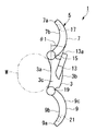
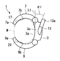
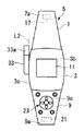
図1から図3はこの発明に係る一実施形態を示す図である。図1,2に示すように、この腕装着型電話機(腕装着型無線機)1は、無線回路を内蔵する通信機本体3と、通信機本体3を腕Wに装着するための装着体5とを備えている。
通信機本体3は、略矩形の板状に形成されており、装着の際に通信機本体3の裏面3aが腕Wに接触するように、側方からみて凹状に湾曲して形成されている。そして、裏面3aの反対側に位置する通信機本体3の表面3bには、時刻や電話番号等の各種情報を表示する表示部11が設けられている。また、裏面3a及び表面3bに隣接する通信機本体3の側面3cには略棒状のアンテナ部13が固定して設けられている。アンテナ部13は、通信機本体3の側面3cの中途部から突出するヘリカルアンテナやホイップアンテナからなる。
1 to 3 are views showing an embodiment according to the present invention. As shown in FIGS. 1 and 2, this arm-mounted telephone (arm-mounted radio) 1 includes a communication device
The communication device
このアンテナ部13は、側方から見てアンテナ部13の取付位置に隣接する裏面3aの接線L1に対して鋭角に傾斜する方向に延びており、通信機本体3の裏面3aに対して一定の傾斜角度θ1で傾斜している。また、アンテナ部13は、後述する第1アームホルダー7の先端部7a側に向かうように、側面3cに対して鋭角に傾斜する方向にも延びており、通信機本体3の側面3cに対して一定の傾斜角度θ2で傾斜している。
装着体5は、第1アームホルダー(第1の筐体)7と第2アームホルダー(第2の筐体)9とから構成されている。これら第1アームホルダー7及び第2アームホルダー9は、腕Wの表面との接触面積が大きくなるように、側方から見てその裏面7b,9bが湾曲して形成されている。
The
The mounting
第1アームホルダー7は、通信機本体3の裏面3a及び側面3cの一端側にヒンジ15によって回転可能に取り付けられている。また、第1アームホルダー7の先端部7aには、腕Wに接触する裏面7b側に露出する通話用のスピーカ17が設けられている。第2アームホルダー9は、通信機本体3の裏面3a及び側面3cの他端側にヒンジ19によって回転可能に取り付けられている。第2アームホルダー9の先端部9aには、腕Wに接触する裏面9b側に露出する通話用のマイクロフォン21が設けられている。また、第2アームホルダー9の表面9cには、通話キー、終話キー、方向キー等の複数の機能キーからなる操作部23が設けられている。
The
これら第1、第2アームホルダー7,9は、通信機本体3に対して回転可能に取り付けられているため、腕装着型無線機1を腕Wに取り付ける際に、腕Wを挟むことができるように構成されている。
そして、これら通信機本体3や第1、第2アームホルダー7,9の内部には、腕装着型電話機1を動作させるための各種電子部品(不図示)が設けられており、これら各種電子部品は、適宜表示部11、操作部23、スピーカ17、マイクロフォン21及びアンテナ部13と電気的に接続されている。
Since the first and
Various electronic parts (not shown) for operating the arm-mounted
以上のように構成された腕装着型無線機1を腕Wに装着する際には、図3に示すように、第1、第2アームホルダー7,9の先端部7a,9aを互いに近づける方向に、第1、第2アームホルダー7,9をそれぞれ通信機本体3に対して回転させる。この状態においては、第1、第2アームホルダー7,9が腕Wを挟んでいるため、通信機本体3が腕Wに固定され、また、通信機本体3及び第1、第2アームホルダー7,9の裏面3a,7b,9bが腕Wの表面に接触している。
When the arm-mounted
また、この状態から腕装着型電話機1により通話を行う際には、図2に示すように、第1、第2アームホルダー7,9の先端部7a,9aを互いに離間させる方向に、第1、第2アームホルダー9を通信機本体3に対して回転させて、腕装着型電話機1を腕Wから取り外す。そして、マイクロフォン21を使用者の口の近傍に配すると共にスピーカ17を使用者の耳の近傍に配するように、第2アームホルダー9や通信機本体3を手で把持する。ここで、アンテナ部13は、把持する手から離間する方向に突出するため、その先端部13aが前記手から離間する位置に配されることになる。
Further, when making a call from the arm-mounted
なお、通信機本体3の裏面3aに対するアンテナ部13の突出方向の傾斜角度θ1は、0°<θ1≦45°、とすることが好ましい。すなわち、傾斜角度θ1が0°である場合には、腕装着型電話機1を腕Wに装着した状態において、アンテナ部13の先端部13aと腕Wとの距離が近くなり、アンテナ部13の感度が劣化するためである。また、傾斜角度θ1が45°よりも大きい場合には、腕装着型電話機1を腕Wに装着した状態において、通信機本体3の表面3bから突出するアンテナ部13の突出長さが大きくなり、アンテナ部13を引っ掛ける不具合が発生して腕装着型電話機1の取り扱いが面倒になるためである。
In addition, it is preferable that the inclination angle θ1 in the protruding direction of the
また、通信機本体3の表面3bから突出するアンテナ部13の先端部13aの突出長さは、0mm以上、かつ、10mm以下とすることが好ましい。すなわち、突出長さが10mmよりも大きい場合には、腕装着型無線機1を腕Wに装着した状態において、腕装着型無線機1の取り扱いが面倒になるためである。なお、突出長さが0mmとは、アンテナ部13の先端部13aが通信機本体3や第1、第2アームホルダー7,9の表面3bから突出しないことを示しており、アンテナ部13の先端部13aが表面3bよりも下側に位置している状態も含んでいる。
Moreover, it is preferable that the protrusion length of the front-end | tip
また、通信機本体3の側面3cに対するアンテナ部13の突出方向の傾斜角度θ2は、0°<θ2≦45°、とすることが好ましい。すなわち、傾斜角度θ2が0°である場合には、アンテナ部13が通信機本体3に近づくことにより、各種電子部品から発生する電磁波がアンテナ部13の先端部13aに作用してアンテナ部13の感度が劣化するためである。また、傾斜角度θ2が45°よりも大きい場合には、通信機本体3の側面3cからのアンテナ部13の突出長さが大きくなり、腕装着型電話機1の小型化が困難となるためである。
Moreover, it is preferable that the inclination angle θ2 in the protruding direction of the
上記のように、この腕装着型電話機1によれば、腕装着型電話機1を腕Wに装着した状態において、アンテナ部13の先端部13aが腕Wから離間した位置に配されるため、アンテナ部13の感度劣化を抑制することができる。そして、このアンテナ部13は通信機本体3の裏面3aに対して傾斜する方向に傾斜角度θ1で突出するため、通信機本体3の表面3bから突出するアンテナ部13の突出長さを小さくすることができる。したがって、腕装着型電話機1を腕に装着した状態において、アンテナ部13を引っ掛ける不具合を防止でき、腕装着型電話機1を容易に取り扱うことができる。
また、アンテナ部13は、ホイップアンテナやヘリカルアンテナからなるため、通信機本体3や装着体5の内部に設けるパッチアンテナよりも安価となり、腕装着型電話機1の製造コストの増加を防止することができる。
As described above, according to the arm-mounted
In addition, since the
さらに、アンテナ部13が通信機本体3の側面3cから離間する方向に傾斜角度θ2で突出しているため、アンテナ部13の先端部13aが通信機本体3から離間する位置に配されることになる。このため、通信機本体3の内部に設けられた各種電子部品からの電磁波によるアンテナ部13の感度劣化を抑制することができる。また、アンテナ部13は、通信機本体3の側面3cに対して傾斜する方向に突出するため、通信機本体3の側面3cから突出するアンテナ部13の突出長さを小さくすることができ、腕装着型電話機1の小型化を図ることができる。
Furthermore, since the
また、スピーカ17及びマイクロフォン21が、それぞれ第1、第2アームホルダー7,9の先端部7a,9aにそれぞれ設けられているため、互いに十分に離間して配されることになる。したがって、通話する際に、マイクロフォン17及びスピーカ21をそれぞれ使用者の口及び耳に近接させて配することができる。したがって、良好な通話状態を確保することができる。
Further, since the
さらに、第1、第2アームホルダー7,9により腕Wを挟むことにより、通信機本体3を腕Wに固定することができる。すなわち、第1、第2アームホルダー7,9を相互に係合させることなく、腕装着型無線機1を腕Wに取り付けることができるため、腕装着型無線機1を腕Wに対して容易に着脱することができる。
また、腕装着型電話機1により通話する際には、アンテナ部13の先端部13aが、通信機本体3や第2アームホルダー9を把持する手から離間して位置するため、通話の際にもアンテナ部13の感度が劣化することを抑制でき、良好な通話状態を確保することができる。
Furthermore, the communication device
Further, when talking on the arm-mounted
なお、上記の実施形態においては、スピーカ17及びマイクロフォン21がそれぞれ第1、第2アームホルダー7,9の先端部7a,9aに設けられているとしたが、これに限ることはなく、少なくともマイクロフォン21が、スピーカ17を設けた第1アームホルダー7とは別の通信機本体3や第2アームホルダー9に設けられていればよい。この場合でも、スピーカ17とマイクロフォン21とを互いに離間させて配することができる。
また、アンテナ部13が、通信機本体3の側面3cから一定方向に突出して設けられるとしたが、これに限ることはなく、例えば、通信機本体3の側面3cに対して揺動可能に取り付けられるとしても構わない。ただし、この構成においては、アンテナ部13の揺動可能な範囲を傾斜角度θ1,θ2の範囲内において行うことが好ましい。この構成の場合には、腕装着型電話機1の使用状況に応じてアンテナ部13の突出長さや感度を調整することができるため、腕装着型電話機1をさらに容易に取り扱うことができる。
In the above embodiment, the
In addition, the
すなわち、腕装着型電話機1を腕Wに装着した状態において、使用者が通信機本体3の表面から突出するアンテナ部13の突出長さを小さくする場合には、傾斜角度θ1が小さくなる方向にアンテナ部13を揺動させればよい。また、使用者が通信機本体3の側面3cから突出するアンテナ部13の突出長さを小さくする場合には、傾斜角度θ2が小さくなる方向にアンテナ部13を揺動させればよい。さらに、アンテナ部13の感度を向上させる場合には、傾斜角度θ1,θ2が大きくなる方向にアンテナ部13を揺動させればよい。
また、例えば、上記の実施形態の構成に加えて、アンテナ部13が、その延出方向に伸縮可能に構成されるとしても構わない。この構成の場合には、アンテナ部13を伸縮させることにより、腕装着型無線機1の使用状況に応じてアンテナ部13の突出長さや感度を調整することができるため、腕装着型無線機1をさらに容易に取り扱うことができる。
That is, in the state where the arm-mounted
For example, in addition to the configuration of the above-described embodiment, the
すなわち、アンテナ部13の感度を向上させる場合には、アンテナ部13を伸ばして、アンテナ部13の先端部13aを腕Wや通信機本体3、第1、第2アームホルダー7,9の裏面3a,7b,9bや側面3cからさらに離間させればよい。また、通信機本体3や第1、第2アームホルダー7,9の表面3bから突出するアンテナ部13の突出長さを小さくする場合には、アンテナ部13を縮めればよい。
That is, in order to improve the sensitivity of the
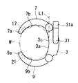
さらに、アンテナ部13は、取付位置に隣接する裏面3aの接線L1に対して鋭角に傾斜する方向に延びているとしたが、これに限ることはなく、少なくともアンテナ部13の基端側から先端側に行くにしたがい、裏面3aから離間する方向に延びていればよい。すなわち、例えば、図4に示すように、アンテナ部31の取付位置に隣接する裏面3aの接線L1に沿って通信機本体3、第1、第2アームホルダー7,9の配列方向に延びるようにアンテナ部31を配するとしても構わない。
Further, although the
この構成においても、腕装着型電話機1を腕Wに装着した状態において、アンテナ部31の先端部31aが腕Wから離間した位置に配されるため、アンテナ部13の感度劣化を抑制することができる。また、通信機本体3や第1、第2アームホルダー7,9の表面3bから突出するアンテナ部13の突出長さを小さくすることもできる。
Even in this configuration, when the arm-mounted
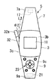
また、アンテナ部13は、通信機本体3の側面3cに対しても鋭角に傾斜する方向に延びているとしたが、少なくともアンテナ部13の取付部分に位置する側面3cの接線に対して鋭角に傾斜する方向に延びていればよい。すなわち、例えば、図5に示すように、通信機本体3の側面3cが外方に膨出して湾曲している場合には、アンテナ部32が、通信機本体3の表面3b側から見て湾曲した側面3cの接線L2に対して鋭角に傾斜する方向に延びるとしても構わない。
In addition, the
また、アンテナ部13,32は側面3cに対して鋭角に傾斜するとしたが、少なくともアンテナ部13の基端側から先端側に行くにしたがい、側面3cから離間する方向に延びていればよい。すなわち、例えば、図6に示すように、通信機本体3の側面3cが外方に膨出して湾曲している場合には、アンテナ部33を湾曲した側面3cの接線L2方向に延ばして配するとしてもよい。この構成においても、アンテナ部33の先端部33aを通信機本体3から離間した位置に配することができるため、アンテナ部33の感度劣化を確実に抑制できる。また、側面3cから突出するアンテナ部33の突出長さを小さくすることができるため、腕装着型無線機の小型化も図ることができる。
Further, although the
また、アンテナ部13は、2つの傾斜角度θ1,θ2で通信機本体3から延びているとしたが、アンテナ部13の先端部13aを腕Wの表面から離間させることのみを考慮する場合には、側面3cに対する傾斜角度θ2の範囲を限定しなくてもよい。また、アンテナ部13の先端部13aを通信機本体3や第1、第2アームホルダー7,9から離間させることのみを考慮する場合には、裏面3aに対する傾斜角度θ1の範囲を限定しなくてもよい。
In addition, although the
また、アンテナ部13,31〜33は、通信機本体3の側面3cに設けられるとしたが、これに限ることはなく、例えば、第1アームホルダー7や第2アームホルダー9の側面に設けられるとしても構わない。ここで、アンテナ部13,31〜33を第1アームホルダー7の側面に設けた場合には、アンテナ部13,31〜33は、上述の実施形態と同様に、第1アームホルダー7の先端部7a側に向けて傾斜することが好ましい。
In addition, the
また、アンテナ部13,31〜33を第2アームホルダー9の側面に設けた場合には、アンテナ部13,31〜33は第2アームホルダー9の先端部9a側に向けて傾斜することが好ましい。すなわち、通話の際には、腕装着型電話機1を腕Wから取り外して第2アームホルダー9や通信機本体3を手で把持するが、ここで、アンテナ部13は、把持する手から離間する方向に突出するため、その先端部13aが前記手から離間する位置に配されることになる。したがって、アンテナ部13の感度劣化を抑制して良好な通話状態を確保することができる。
Further, when the
さらに、無線回路は通信機本体3に内蔵されるとしたが、これに限ることはなく、第1、第2アームホルダー7,9に内蔵されるとしても構わない。
また、第1、第2アームホルダー7,9により装着体5が構成されるとしたが、これに限ることはなく、装着体は、少なくとも通信機本体3を腕Wに固定できるように、通信機本体3に対して回転可能に取り付けられていればよい。したがって、装着体は、例えば、1つのアームホルダーから構成されるとしてもよいし、3つ以上のアームホルダーを連結して構成されるとしても構わない。
Further, although the wireless circuit is built in the communication device
In addition, although the mounting
さらに、腕装着型電話機1について述べたが、これに限ることはなく、少なくとも各種情報を送受信するためのアンテナ部13を備えた腕装着型無線機であればよい。
以上、本発明の実施形態について図面を参照して詳述したが、具体的な構成はこの実施形態に限られるものではなく、本発明の要旨を逸脱しない範囲の設計変更等も含まれる。
Furthermore, although the arm-mounted
As mentioned above, although embodiment of this invention was explained in full detail with reference to drawings, the concrete structure is not restricted to this embodiment, The design change etc. of the range which does not deviate from the summary of this invention are included.
1 腕装着型電話機(腕装着型無線機)
3 通信機本体
3a 裏面
3c 側面
5 装着体
7 第1アームホルダー(第1の筐体)
9 第2アームホルダー(第2の筐体)
13,31〜33 アンテナ部
13a,31a〜33a 先端部
17 スピーカ
19 マイクロフォン
L1,L2 接線
θ1 傾斜角度
θ2 傾斜角度
1 Arm-mounted phone (arm-mounted radio)
3
9 Second arm holder (second housing)
13, 31 to 33
Claims (18)
前記通信機本体を腕に装着するための装着体と、
前記通信機本体若しくは前記装着体の側面から突出して設けられたアンテナ部とを備え、
前記アンテナ部が、前記アンテナ部の基端側から先端側に行くにしたがい、前記腕に接触する前記通信機本体若しくは前記装着体の裏面から離間する方向に延びていることを特徴とする腕装着型無線機。 A communication device that transmits and receives signals;
A mounting body for mounting the communication device body on an arm;
An antenna unit provided to project from the side surface of the communication device main body or the mounting body,
The arm portion extends in a direction away from the back surface of the communication device main body or the mounting body in contact with the arm as the antenna portion goes from the proximal end side to the distal end side of the antenna portion. Type radio.
前記通信機本体を腕に装着するための装着体と、
前記通信機本体若しくは前記装着体の側面から突出して設けられたアンテナ部とを備え、
前記アンテナ部が、前記アンテナ部の基端側から先端側に行くにしたがい、前記通信機本体若しくは前記装着体の側面から離間する方向に延びていることを特徴とする腕装着型無線機。 A communication device that transmits and receives signals;
A mounting body for mounting the communication device body on an arm;
An antenna unit provided to project from the side surface of the communication device main body or the mounting body,
The arm-mounted radio device, wherein the antenna unit extends in a direction away from a side surface of the communication device main body or the mounting body as it goes from the base end side to the front end side of the antenna unit.
前記アンテナ部の延出方向が、前記取付部分における前記側面の接線方向に一致していることを特徴とする請求項11に記載の腕装着型無線機。 The side surface located at the mounting portion of the antenna portion is curved so as to bulge outward,
The arm-mounted radio device according to claim 11, wherein an extending direction of the antenna unit coincides with a tangential direction of the side surface of the attachment portion.
前記第1の筐体に通話用のスピーカが設けられ、前記通信機本体若しくは前記第2の筐体の少なくともいずれか一方に通話用のマイクロフォンが設けられていることを特徴とする請求項1から請求項16のいずれか1項に記載の腕装着型無線機。 A first housing rotatably attached to the communication device main body on one end side of the side surface and the back surface of the communication device main body; and the other end side of the side surface and the back surface of the communication device main body. And a second housing rotatably attached to the communication device main body,
The speaker for a call is provided in the first casing, and a microphone for a call is provided in at least one of the communication device main body or the second casing. The arm-mounted radio device according to claim 16.
前記腕に取り付ける際に、前記第1の筐体及び第2の筐体により前記腕を挟むことを特徴とする請求項1から請求項16のいずれか1項に記載の腕装着型無線機。 A first housing rotatably attached to the communication device main body on one end side of the side surface and the back surface of the communication device main body; and the other end side of the side surface and the back surface of the communication device main body. And a second housing rotatably attached to the communication device main body,
The arm-mounted radio device according to any one of claims 1 to 16, wherein the arm is sandwiched between the first casing and the second casing when attached to the arm.
Priority Applications (1)
| Application Number | Priority Date | Filing Date | Title |
|---|---|---|---|
| JP2004105355A JP2005295072A (en) | 2004-03-31 | 2004-03-31 | Arm-mounted radio |
Applications Claiming Priority (1)
| Application Number | Priority Date | Filing Date | Title |
|---|---|---|---|
| JP2004105355A JP2005295072A (en) | 2004-03-31 | 2004-03-31 | Arm-mounted radio |
Publications (1)
| Publication Number | Publication Date |
|---|---|
| JP2005295072A true JP2005295072A (en) | 2005-10-20 |
Family
ID=35327546
Family Applications (1)
| Application Number | Title | Priority Date | Filing Date |
|---|---|---|---|
| JP2004105355A Pending JP2005295072A (en) | 2004-03-31 | 2004-03-31 | Arm-mounted radio |
Country Status (1)
| Country | Link |
|---|---|
| JP (1) | JP2005295072A (en) |
-
2004
- 2004-03-31 JP JP2004105355A patent/JP2005295072A/en active Pending
Similar Documents
| Publication | Publication Date | Title |
|---|---|---|
| ES2585752T3 (en) | Portable terminal | |
| US6212414B1 (en) | Wrist-carried radiotelephone | |
| EP1388910B1 (en) | Portable radio communication apparatus provided with boom portion with through hole | |
| WO2003103173A1 (en) | Portable wireless terminal | |
| TWI380502B (en) | Antennas for handheld electronic devices | |
| JP2518436B2 (en) | Mobile phone | |
| JP2003069441A (en) | Foldable mobile phone | |
| CN1773769B (en) | Antenna device for portable terminal | |
| JP2012248947A (en) | Portable wireless device | |
| US20140079240A1 (en) | Bluetooth headset | |
| CN101060722B (en) | Earset | |
| US5796822A (en) | Portable electronic device having a rotatable earpiece | |
| CA2523069C (en) | Extended antenna support for a wireless communications device | |
| EP2086054A1 (en) | Cellular phone | |
| JPH11331017A (en) | Portable mobile communication terminal | |
| JP4266100B2 (en) | Portable wireless terminal | |
| JP2001217627A (en) | Mobile phone | |
| JP2000286939A (en) | Portable wristwatch radio telephone set | |
| CN216120708U (en) | TWS earphone with double antennas | |
| JP4298285B2 (en) | Communication device | |
| JP2002171112A (en) | Mobile phone | |
| KR100619090B1 (en) | Bluetooth Headset with Bow Type Ear Hook | |
| JP3105875U (en) | Mobile phone | |
| KR100996110B1 (en) | Touch pen antenna | |
| JP2005005892A (en) | Portable information terminal device |