JP2005295020A - Television receiver provided with ground structure of tuner - Google Patents
Television receiver provided with ground structure of tuner Download PDFInfo
- Publication number
- JP2005295020A JP2005295020A JP2004104357A JP2004104357A JP2005295020A JP 2005295020 A JP2005295020 A JP 2005295020A JP 2004104357 A JP2004104357 A JP 2004104357A JP 2004104357 A JP2004104357 A JP 2004104357A JP 2005295020 A JP2005295020 A JP 2005295020A
- Authority
- JP
- Japan
- Prior art keywords
- tuner
- ground
- lead wire
- dbμv
- ground structure
- Prior art date
- Legal status (The legal status is an assumption and is not a legal conclusion. Google has not performed a legal analysis and makes no representation as to the accuracy of the status listed.)
- Pending
Links
- 230000010355 oscillation Effects 0.000 claims abstract description 44
- WABPQHHGFIMREM-UHFFFAOYSA-N lead(0) Chemical compound [Pb] WABPQHHGFIMREM-UHFFFAOYSA-N 0.000 claims abstract description 37
- 239000000758 substrate Substances 0.000 claims description 22
- 230000005855 radiation Effects 0.000 abstract description 28
- 238000005259 measurement Methods 0.000 description 13
- 230000000694 effects Effects 0.000 description 3
- 239000002184 metal Substances 0.000 description 3
- 230000007257 malfunction Effects 0.000 description 2
- 238000000034 method Methods 0.000 description 2
- 238000001228 spectrum Methods 0.000 description 2
- 230000002159 abnormal effect Effects 0.000 description 1
- 230000002411 adverse Effects 0.000 description 1
- 238000006243 chemical reaction Methods 0.000 description 1
- 238000007796 conventional method Methods 0.000 description 1
- 238000013461 design Methods 0.000 description 1
- 230000002542 deteriorative effect Effects 0.000 description 1
- 238000010892 electric spark Methods 0.000 description 1
- 238000007689 inspection Methods 0.000 description 1
- 238000005728 strengthening Methods 0.000 description 1
- 229920003002 synthetic resin Polymers 0.000 description 1
- 239000000057 synthetic resin Substances 0.000 description 1
Images


Landscapes
- Structure Of Receivers (AREA)
Abstract
Description
本発明は、発振回路が内蔵されたチュ−ナーの不要輻射を低減させることを目的としたチューナーのアース構造を備えたテレビ受信装置に関するものである。 The present invention relates to a television receiver having a tuner ground structure for the purpose of reducing unnecessary radiation of a tuner incorporating an oscillation circuit.
局部発振回路が内蔵されたチュ−ナーとは、たとえば、特許文献1の図1に示されたような構造をしている。この図のチューナーは入力端子や基板上の回路に及ぼす影響を配慮して後寄り上方に局部発振回路が配置されているが、前寄りや下方に局部発振回路が配置されたチューナーもある。チューナーの内部では受信した電波に局部発振回路で発生させた電波をぶつけて周波数を変換させる処理を行っている。変換後の周波数である中間周波数(IF周波数)はFMラジオでは10.7MHz、AMラジオでは約450KHz、テレビは日本では58.75MHz、アメリカでは45.75MHz、ドイツでは38.9MHzとなっている。この時の電波がチューナーから外に漏れて周囲に放射されると、様々な悪い影響を及ぼす不要輻射が発生する。チューナーを備えた電子装置は受信機と呼ばれているが、実際は電波を発射する送信機でもある。現在、不要輻射は大きな社会問題となっている。電子機器の高機能化、高品位化、高周波化、デジタル化、高速デジタル化、多機能化、パーソナル・携帯化、使用周波数の高域化にともない、電波環境が急速に悪化している。不要輻射による電波障害の事例としては、たとえば、ロボットの増設・点検中のアーク溶接機使用による暴走、クレーンの電気火花によるNC旋盤の誤作動、ノートパソコンの使用による飛行機の計器類の誤作動、民家のテレビブースタの異常発振による無線航空陸上局への妨害、走行中の移動電話によるエンジン停止、トラックの違法無線により隣の自動車のエンジンが高速回転を起こして暴走事故、などがある。 The tuner with the built-in local oscillation circuit has a structure as shown in FIG. In the tuner of this figure, the local oscillation circuit is arranged on the rear side and the upper side in consideration of the influence on the input terminal and the circuit on the substrate, but there is a tuner in which the local oscillation circuit is arranged on the front side and the lower side. Inside the tuner, the radio wave generated by the local oscillation circuit is collided with the received radio wave to convert the frequency. The intermediate frequency (IF frequency) after conversion is 10.7 MHz for FM radio, about 450 KHz for AM radio, 58.75 MHz for Japan, 45.75 MHz for the United States, and 38.9 MHz for Germany. If radio waves at this time leak out from the tuner and are radiated to the surroundings, unnecessary radiation having various adverse effects is generated. An electronic device equipped with a tuner is called a receiver, but is actually a transmitter that emits radio waves. Currently, unwanted radiation is a major social problem. The radio wave environment is rapidly deteriorating as electronic devices become more sophisticated, high-grade, high-frequency, digitized, digitalized at high speed, multifunctional, personal and portable, and higher in frequency. Examples of radio interference due to unwanted radiation include runaway due to the use of arc welders during robot expansion and inspection, malfunction of NC lathes due to electric sparks of cranes, malfunction of airplane instruments due to use of notebook computers, There are disturbances to the radio aviation land station due to abnormal oscillation of a private TV booster, engine stop by a mobile phone while traveling, illegal runaway accident due to the engine of the adjacent car causing high speed rotation due to illegal radio of the truck.
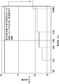
不要輻射に対する規制は各所で行われている。たとえば、アメリカにおいては、FCC(連邦通信委員会)の規定があり、テレビ、ラジオ、オーディオ、VTRなどは、FCCのパート15(無線周波装置)のサブパートB(非意図的放射機器)のクラスB(住宅環境での使用のために販売されているデジタル機器)の中に含まれる。さらに周波数に応じた不要輻射(放射雑音)の限度値が定められており、周波数216MHz超〜960MHz以下の場合、限度値は46dBμV/m以下と定められている(図11参照)。 Regulations on unnecessary radiation are performed in various places. For example, in the United States, there is a provision of FCC (Federal Communications Commission), and TV, radio, audio, VTR, etc. are class B of subpart B (unintentional radiating equipment) of FCC Part 15 (Radio Frequency Equipment). (Digital equipment sold for use in a residential environment). Further, a limit value of unnecessary radiation (radiation noise) according to the frequency is determined. When the frequency is higher than 216 MHz and 960 MHz or lower, the limit value is determined to be 46 dBμV / m or lower (see FIG. 11).
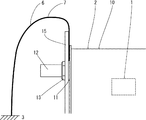
不要輻射を低減するための従来の方法は、図10に示すように、チューナー2を導電性を有したチューナーパック10で外装し、チューナーパック10に導電性を有した足14を形成し、足14を基板4に取り付け、セット背面のシールド板15の穴からRF端子12を出してナット11で締めビス16とチューナー2前面のビス穴17でシールド板15とチューナー2を共締めする。アースは、内側で発せられた局部発振電波をチューナーパック10で遮蔽し、足14と基板4の導電部との接点からアース3を取る構造をしている。
As shown in FIG. 10, a conventional method for reducing unwanted radiation is to coat the
上記した従来のアース構造を有したチューナーでは、不要輻射がまだ十分には低減できていない。発振電波の漏れをさらに防ぐ必要がある。 In the tuner having the above-described conventional ground structure, unnecessary radiation has not been sufficiently reduced. It is necessary to further prevent leakage of oscillation waves.
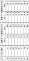
図12の左側のデータは、従来のチューナーのアース構造における不要輻射を測定した数値である。オープンサイトにおいて供試機器と測定用の受信アンテナを所定の距離に配置し、動作やケーブルの配置など供試機器の状態でアンテナの高さや角度(垂直方向と水平方向)を調節して所定の周波数をスペクトラムアナライザで測定した(図13参照。)。アンテナと機器の距離が3m、アンテナの高さを0〜4mの範囲で調節するなどして、一番ノイズのレベルが高くなる受信するポイントで測定した。サンプルとしてアメリカ仕様のテレビ受信装置を用い、8つのチャンネルで不要輻射を測定した。14chにおける局部発振周波数(Freq.)が517MHzの場合、垂直方向測定値(Horiz.)が42.6dBμV/m、水平測定値(Vert.)が40.6dBμV/mであった。20chにおける局部発振周波数が553MHzの場合、垂直方向測定値が43.2dBμV/m、水平方向測定値40.7dBμV/mであった。28chにおける局部発振周波数が601MHzの場合、垂直方向測定値が39.4dBμV/m、水平方向測定値が39.0dBμV/mであった。36chにおける局部発振周波数が649MHzの場合、垂直方向測定値が41.6dBμV/m、水平方向測定値が42.9dBμV/mであった。44chにおける局部発振周波数が697MHzの場合、垂直方向測定値が42.2dBμV/m、水平方向測定値が44.3dBμV/mであった。54chにおける局部発振周波数が757MHzの場合、垂直方向測定値が42.4dBμV/m、水平方向測定値が43.3dBμV/mであった。61chにおける局部発振周波数が799MHzの場合、垂直方向測定値が45.7dBμV/m、水平方向測定値が46.1dBμV/mであった。69chにおける局部発振周波数が847MHzの場合、垂直方向測定値が44.8dBμV/m、水平方向測定値が45.5dBμV/mであった。上記した61chにおける局部発振周波数が799MHzの水平方向測定値の46.1dBμV/mは、FCCの定める限度値の46.0dBμV/mをオーバーしている。 The data on the left side of FIG. 12 is a numerical value obtained by measuring unnecessary radiation in the ground structure of the conventional tuner. At the open site, place the EUT and the receiving antenna for measurement at a predetermined distance, and adjust the height and angle (vertical and horizontal) of the antenna according to the status of the EUT such as operation and cable arrangement. The frequency was measured with a spectrum analyzer (see FIG. 13). The measurement was performed at the point of reception where the noise level was highest, for example, by adjusting the distance between the antenna and the device within a range of 3 m and the height of the antenna from 0 to 4 m. Using an American television receiver as a sample, unnecessary radiation was measured on 8 channels. When the local oscillation frequency (Freq.) At 14 ch was 517 MHz, the vertical direction measurement value (Horiz.) Was 42.6 dBμV / m, and the horizontal measurement value (Vert.) Was 40.6 dBμV / m. When the local oscillation frequency in 20ch was 553 MHz, the measured value in the vertical direction was 43.2 dBμV / m and the measured value in the horizontal direction was 40.7 dBμV / m. When the local oscillation frequency at 28 ch was 601 MHz, the measured value in the vertical direction was 39.4 dBμV / m and the measured value in the horizontal direction was 39.0 dBμV / m. When the local oscillation frequency at 36 ch was 649 MHz, the measured value in the vertical direction was 41.6 dBμV / m, and the measured value in the horizontal direction was 42.9 dBμV / m. When the local oscillation frequency at 44 ch was 697 MHz, the measured value in the vertical direction was 42.2 dBμV / m and the measured value in the horizontal direction was 44.3 dBμV / m. When the local oscillation frequency at 54 ch was 757 MHz, the measured value in the vertical direction was 42.4 dBμV / m and the measured value in the horizontal direction was 43.3 dBμV / m. When the local oscillation frequency at 61ch was 799 MHz, the measured value in the vertical direction was 45.7 dBμV / m and the measured value in the horizontal direction was 46.1 dBμV / m. When the local oscillation frequency at 69 ch was 847 MHz, the measured value in the vertical direction was 44.8 dBμV / m and the measured value in the horizontal direction was 45.5 dBμV / m. The horizontal measurement value of 46.1 dBμV / m at the above-mentioned 61ch local oscillation frequency of 799 MHz exceeds the limit value determined by FCC of 46.0 dBμV / m.
従来のアース構造には、いくつかの問題点がある。第1に、セット背面がシールド板15であれば、シールド板15とチューナーをビスで共締めすることで、チューナーのアースは、基板とシールド板15の両方からとることができる。なお、機器によっては、セット背面が合成樹脂製のパネルのものもあり、このような場合にはビスで共締めしても、チューナーの固定はできても、アースをとることはできない。それだけアースが弱くなる(図10参照)。第2に、足と局部発振回路とが離れた位置にある(図9参照。)。足を局部発振回路の近くに移動させることは構造上不可能であるし、局部発振回路を基板に近づけることも不要輻射が基板回路に与える影響を考慮するとやはり不可能である。局部発振回路から発せられた電波はあらゆる方向に放射されてゆくが、アースの位置が離れていたのでは、アースによる不要輻射を低減させる効果が低下する。第3に、結論として、アースが弱く不安定であるため、チューナーから局部発振電波が漏れ出してしまい、不要輻射を十分に低減させることができない。
There are several problems with the conventional ground structure. First, if the back surface of the set is the
本発明は、アースを強化して不要輻射を大幅に低減させることのできるチューナーのアース構造を備えたテレビ受信装置を提供することを目的とする。 An object of the present invention is to provide a television receiver having a tuner grounding structure that can significantly reduce unnecessary radiation by strengthening the grounding.
上記従来の課題を解決するために、請求項1に係る本発明のチューナーのアース構造を備えたテレビ受信装置は、発振回路を内蔵したチューナーのアース構造において、チューナーと基板を固定しチューナーの基板に面した導電部と基板に配された導電部とを直接アースさせてなる第1アースと、基板に面していないチューナーの導電部とチューナーの導電部以外の導電部とをリード線を介した配線によってアースさせてなる第2アースとを備え、前記リード線のチューナー側を発振回路の近傍に接続したことを特徴とする。 In order to solve the above-described conventional problems, a television receiver having the tuner ground structure according to the first aspect of the present invention is a tuner ground structure in which a tuner and a substrate are fixed in a tuner ground structure incorporating an oscillation circuit. The first ground formed by directly grounding the conductive portion facing the conductive portion and the conductive portion disposed on the substrate, and the conductive portion of the tuner not facing the substrate and the conductive portions other than the conductive portion of the tuner via lead wires And a second ground that is grounded by the wiring, and the tuner side of the lead wire is connected in the vicinity of the oscillation circuit.
また、請求項2に係る本発明のチューナーのアース構造を備えたテレビ受信装置は、上記した第2アースのチューナー側とリード線の端部の両方に互いに着脱可能である導電性接続端子を有し、該接続端子を用いてチューナーとリード線とを接続したことを特徴とする。
The television receiver having the tuner ground structure of the present invention according to
また、請求項3に係る本発明のチューナーのアース構造を備えたテレビ受信装置は、上記した第2アースのリード線の端部にコ字状の導電性接続具を有し、該接続具の対向した内側の面で導電性を有したチューナーパックを挟止してチューナーとリード線とを接続したことを特徴とする。 According to a third aspect of the present invention, a television receiver having the tuner ground structure of the present invention has a U-shaped conductive connector at the end of the second ground lead wire. A tuner pack having conductivity is sandwiched between the opposed inner surfaces, and the tuner and the lead wire are connected.
また、請求項4に係る本発明のチューナーのアース構造を備えたテレビ受信装置は、上記した第2アースのリード線の端部に導電性ワッシャーを有し、該ワッシャーをチューナーのRF端子に通してナットで固定しチューナーとリード線とを接続したことを特徴とする。 According to a fourth aspect of the present invention, there is provided a television receiver having the tuner grounding structure of the present invention having a conductive washer at the end of the lead wire of the second ground, and passing the washer through the RF terminal of the tuner. It is characterized in that it is fixed with a nut and the tuner and the lead wire are connected.
本発明によれば、アースを強化安定させ、発振電波の漏れを低減し、チューナーから飛び出す不要輻射の値を大幅に低減させることができる。チューナー側の第2アースの端を不要輻射の発生ポイントである発振回路の近傍に設けることで、不要輻射を低減させる効果を高めることができる。第2アースのチューナーと反対側の端は、リード線を用いて基板以外の導電部とをつなぐため、チューナーから離れた近接していない遠くの場所にアースを取ることができる。チューナーと基板が近接した第1アースと、チューナーとチューナーの導電部以外の導電部をリード線でつないだ第2アースとにより、長短のアースを併用することで安定したアースを実現することができる。ルートの異なる第1アースと第2アースを2つ併設することで、アースを大幅に強化することができる。従来のアース構造をそのまま利用できるので、大幅な設計の変更を必要としない。 According to the present invention, it is possible to reinforce and stabilize the ground, reduce the leakage of the oscillating radio wave, and greatly reduce the value of unnecessary radiation that jumps out of the tuner. By providing the end of the second ground on the tuner side in the vicinity of the oscillation circuit that is the generation point of unnecessary radiation, the effect of reducing unnecessary radiation can be enhanced. Since the end opposite to the tuner of the second ground is connected to a conductive part other than the substrate using a lead wire, it can be grounded at a distant place away from the tuner. A stable ground can be realized by using a short earth together with a first earth where the tuner and the substrate are close to each other and a second earth where a conductive part other than the conductive part of the tuner and the tuner is connected by a lead wire. . By providing two first and second grounds with different routes, the ground can be greatly strengthened. Since the conventional ground structure can be used as it is, no significant design changes are required.
請求項2、3又は4の発明によれば、第2アースのリード線をチューナーに簡単に接続でき、ビス止めの手間が要らない。
According to the invention of
請求項2又は3の発明によれば、工具を用いずに手で第2アースのリード線をチューナーに接続することができる。
According to the invention of
請求項3又は4の発明によれば、従来のチューナーをそのまま利用して、第2アースのリード線を接続することができる。 According to the third or fourth aspect of the present invention, the second ground lead can be connected using the conventional tuner as it is.
請求項2の発明によれば、チューナーの内蔵された発振回路に近い位置に第2アースのリード線を接続することができ、接続位置の変更にも簡単に対応することができる。 According to the second aspect of the present invention, the lead wire of the second ground can be connected to a position close to the oscillation circuit in which the tuner is built, and the change of the connection position can be easily handled.
以下、本発明に係るテレビ受信装置を実施するための最良の形態の一例について図面を参照しながら説明するが、本発明は本実施の形態にのみ限定されるべきものではない。 Hereinafter, an example of the best mode for carrying out a television receiver according to the present invention will be described with reference to the drawings. However, the present invention should not be limited only to the present embodiment.
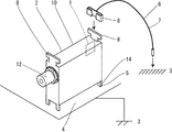
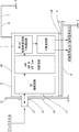
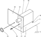
図中2は、局部発振回路などの発振回路1が内蔵されたチューナーパック10で外装されたチューナーである。図示したチューナー2は縦型であるが、これに限定されない。図中12は、アンテナに接続されるRF端子である。図中14は、基板4面にチューナー2を取り付けるための導電性の足である。図中3は、アースをあらわしている。図中5は、チューナー2の足14と基板4の導電部パターンが接触している第1アースである。図中7は、基板4に面していないチューナー2の導電部と、チューナー2の導電部以外の導電部とを、リード線6を介した配線によって接続させた第2アースである。なお、チューナー2の導電部に取り付けたリード線6を接続するのは基板4の導電部であっても良いものである。
In the figure,
図1、図2中8は、第2アース7のリード線6とチューナー2を接続するための導電性の接続端子である。接続端子8は、チューナー側とリード線の端部の両方に互いに着脱可能な形状の金属端子が設けられる。チューナー2側の接続端子8は、チューナー形状を変更しあらかじめ発振回路1の近くに接続端子8の一方を形成しておくことで、チューナー2上部にリード線6の付いたもう一方の接続端子8を接続可能にしている。接続端子8の形状は図示したものに限定されない。
1 and 2,
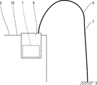
図3、図4中9は、第2アース7のリード線6とチューナー2を接続するための導電性の接続具である。接続具9は、リード線の付いたコ字状の金属部品である。接続具9の対向した内側の面でチューナーパック10をクリップ状に挟止して、チューナー2とリード線6とを接続している。接続具9の形状は図示したものに限定されない。
3 and 4,
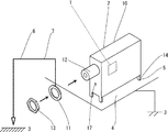
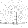
図5、図6中11は、第2アース7のリード線6が付いた導電性のワッシャーである。金属製のワッシャー11を、チューナーのRF端子に通して、六角ナット13で締めて固定する。チューナー2前面、ワッシャー11、セット背面のシールド板15、ナット13の順に重なり、ナット13とチューナー2を共締めする。ナット13の形状を六角に限定する必要はない。
In FIG. 5 and FIG. 6,
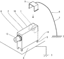
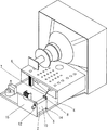
図7は、本発明のアース構造を実施したテレビチューナーが内蔵されたテレビ(テレビ受信装置)である。第2アース7のリード線6の接続は、チューナー2側は接続端子8で接続され、チューナー2の反対側はチューナー2から離れたシャーシの上板にビス端子で接続されている。図8は、テレビチューナーの内部回路と、本発明のアース構造との関係をあらわしている。第1アース5は足14からチューナー2と近接した基板4へとアースされ、第2アース7はチューナー2の不要輻射の発生ポイントである局部発振回路などの発振回路1近傍の位置からリード線6の配線を介してチューナーから離れた導電部へとアースされている。こうすることで、アースを安定化させ、強化させることができる。
FIG. 7 shows a television (television receiver) incorporating a television tuner that implements the ground structure of the present invention. The
図12の左側のデータは前記した従来のアース構造(通常アース構造)の場合の不要輻射の数値であり、右側のデータは図7におけるテレビのチューナーに実施された本願アース構造における不要輻射の数値である。どちらもサンプルとして同じテレビ用のチューナー2を使用し、オープンサイトにおいて供試機器と受信アンテナを所定の距離に配置し、動作やケーブルの配置など供試機器の状態でアンテナの高さや角度を調節して所定の周波数をスペクトラムアナライザで測定した。測定方法は、発明が解決しようとする課題のところで前記したものと同じである。チャンネルは8つである。14chにおける局部発振周波数が517MHzの場合、通常アース構造では42.6dBμV/mあった垂直方向測定値が本願アース構造では32.0dBμV/mに低減し、通常アース構造では40.6dBμV/mあった水平方向測定値が本願アース構造では30.7dBμV/mに低減した。20chにおける局部発振周波数が553MHzの場合、通常アース構造では43.2dBμV/mあった垂直方向測定値が本願アース構造では33.9dBμV/mに低減し、通常アース構造では40.7dBμV/mあった水平方向測定値が本願アース構造では32.5dBμV/mに低減した。28chにおける局部発振周波数が601MHzの場合、通常アース構造では39.4dBμV/mあった垂直方向測定値が本願アース構造では34.0dBμV/mに低減し、通常アース構造では39.0dBμV/mあった水平方向測定値が本願アース構造では33.8dBμV/mに低減した。36chにおける局部発振周波数が649MHzの場合、通常アース構造では41.6dBμV/mあった垂直方向測定値が本願アース構造では30.8dBμV/mに低減し、通常アース構造では42.9dBμV/mあった水平方向測定値が本願アース構造では34.5dBμV/mに低減した。44chにおける局部発振周波数が697MHzの場合、通常アース構造では42.2dBμV/mあった垂直方向測定値が本願アース構造では34.9dBμV/mに低減し、通常アース構造では44.3dBμV/mあった水平方向測定値が本願アース構造では38.4dBμV/mに低減した。54chにおける局部発振周波数が757MHzの場合、通常アース構造では42.4dBμV/mあった垂直方向測定値が本願アース構造では38.1dBμV/mに低減し、通常アース構造では43.3dBμV/mあった水平方向測定値が本願アース構造では39.1dBμV/mに低減した。61chにおける局部発振周波数が799MHzの場合、通常アース構造では45.7dBμV/mあった垂直方向測定値が本願アース構造では38.4dBμV/mに低減し、通常アース構造では46.1dBμV/mあった水平方向測定値が本願アース構造では39.6dBμV/mに低減した。69chにおける局部発振周波数が847MHzの場合、通常アース構造では44.8dBμV/mあった垂直方向測定値が本願アース構造では39.4dBμV/mに低減し、通常アース構造では45.5dBμV/mあった水平方向測定値が本願アース構造では39.7dBμV/mに低減した。すべての値が本願アース構造により不要輻射が低減されたことを証明している。上記した61chの水平方向測定値における、通常アース構造の不要輻射はFCCの定めた限界値である46.0dBμV/mを超える46.1dBμV/mを記録したが、本願アース構造によれば限界値以下の39.6dBμV/mにまで低減されている。上記した14chの垂直方向測定値の場合で従来の通常アース構造と本願アース構造を比較してみると、本願アース構造によって不要輻射が25%も低減される。
The data on the left side of FIG. 12 is a numerical value of unnecessary radiation in the case of the above-described conventional ground structure (normal ground structure), and the data on the right side is a numerical value of unnecessary radiation in the ground structure of the present application implemented in the TV tuner in FIG. It is. Both use the
1 発振回路
2 チューナー
3 アース
4 基板
5 第1アース
6 リード線
7 第2アース
8 接続端子
9 接続具
10 チューナーパック
11 ワッシャー
12 RF端子
13 ナット
DESCRIPTION OF
Claims (4)
Priority Applications (1)
| Application Number | Priority Date | Filing Date | Title |
|---|---|---|---|
| JP2004104357A JP2005295020A (en) | 2004-03-31 | 2004-03-31 | Television receiver provided with ground structure of tuner |
Applications Claiming Priority (1)
| Application Number | Priority Date | Filing Date | Title |
|---|---|---|---|
| JP2004104357A JP2005295020A (en) | 2004-03-31 | 2004-03-31 | Television receiver provided with ground structure of tuner |
Publications (2)
| Publication Number | Publication Date |
|---|---|
| JP2005295020A true JP2005295020A (en) | 2005-10-20 |
| JP2005295020A5 JP2005295020A5 (en) | 2006-12-14 |
Family
ID=35327503
Family Applications (1)
| Application Number | Title | Priority Date | Filing Date |
|---|---|---|---|
| JP2004104357A Pending JP2005295020A (en) | 2004-03-31 | 2004-03-31 | Television receiver provided with ground structure of tuner |
Country Status (1)
| Country | Link |
|---|---|
| JP (1) | JP2005295020A (en) |
Cited By (1)
| Publication number | Priority date | Publication date | Assignee | Title |
|---|---|---|---|---|
| JP2009049629A (en) * | 2007-08-17 | 2009-03-05 | Funai Electric Co Ltd | Earth grounding structure of tuner |
-
2004
- 2004-03-31 JP JP2004104357A patent/JP2005295020A/en active Pending
Cited By (2)
| Publication number | Priority date | Publication date | Assignee | Title |
|---|---|---|---|---|
| JP2009049629A (en) * | 2007-08-17 | 2009-03-05 | Funai Electric Co Ltd | Earth grounding structure of tuner |
| US7633762B2 (en) | 2007-08-17 | 2009-12-15 | Funai Electric Co., Ltd. | Ground structure for a tuner |
Similar Documents
| Publication | Publication Date | Title |
|---|---|---|
| US10601123B2 (en) | Vehicular antenna device | |
| JP3883847B2 (en) | In-vehicle signal processor | |
| JP5070978B2 (en) | ANTENNA, PORTABLE TERMINAL HAVING THE SAME, AND ELECTRIC DEVICE | |
| US9106107B2 (en) | Contactless power transmission device provided in a vehicle for charging an electronic device | |
| CN113226854B (en) | Composite antenna device for vehicle | |
| US5668701A (en) | Up-down tuner having a grounding plate provided with generally L-shaped soldering portions | |
| US20070188384A1 (en) | Co-construction with antenna and EMI shield | |
| JP4338710B2 (en) | Receiver and receiver system | |
| JP2005295020A (en) | Television receiver provided with ground structure of tuner | |
| US12250765B2 (en) | Anti-interference surface mount electronic component | |
| JPH0946125A (en) | Radio wave receiver | |
| JP4137111B2 (en) | In-vehicle signal processing apparatus and in-vehicle radar apparatus | |
| JP2000059063A (en) | Shield case with opening | |
| JP2767998B2 (en) | Electronic component shield structure | |
| JP5628964B1 (en) | Radar equipment | |
| US20200060050A1 (en) | Electronic control device | |
| JP2007150701A (en) | Installation structure of amplifying device | |
| CN217982806U (en) | Liquid crystal display control system and liquid crystal display | |
| US7120409B2 (en) | High frequency module and radio device using the same | |
| JP2003179509A (en) | Receiver | |
| JPH0625028Y2 (en) | Printed board for high frequency noise prevention | |
| JP3982529B2 (en) | Electronic tuner | |
| JP4186731B2 (en) | Radio circuit | |
| KR200215068Y1 (en) | circuit for defilading elctromagnetic wave using image planes | |
| WO2025009141A1 (en) | Antenna device |
Legal Events
| Date | Code | Title | Description |
|---|---|---|---|
| A521 | Written amendment |
Free format text: JAPANESE INTERMEDIATE CODE: A523 Effective date: 20061026 |
|
| A621 | Written request for application examination |
Free format text: JAPANESE INTERMEDIATE CODE: A621 Effective date: 20061026 |
|
| A131 | Notification of reasons for refusal |
Free format text: JAPANESE INTERMEDIATE CODE: A131 Effective date: 20080603 |
|
| A02 | Decision of refusal |
Free format text: JAPANESE INTERMEDIATE CODE: A02 Effective date: 20081007 |