JP2005294969A - Transceiver system - Google Patents
Transceiver system Download PDFInfo
- Publication number
- JP2005294969A JP2005294969A JP2004103618A JP2004103618A JP2005294969A JP 2005294969 A JP2005294969 A JP 2005294969A JP 2004103618 A JP2004103618 A JP 2004103618A JP 2004103618 A JP2004103618 A JP 2004103618A JP 2005294969 A JP2005294969 A JP 2005294969A
- Authority
- JP
- Japan
- Prior art keywords
- portable
- call
- handset
- transmission
- receiver
- Prior art date
- Legal status (The legal status is an assumption and is not a legal conclusion. Google has not performed a legal analysis and makes no representation as to the accuracy of the status listed.)
- Pending
Links
Images
Landscapes
- Sub-Exchange Stations And Push- Button Telephones (AREA)
- Mobile Radio Communication Systems (AREA)
Abstract
Description
本発明は、送受話システムに係わり、特に無線通信を介した送受話機能を備えた携帯型送受話装置と、非携帯型送受話装置とを有する送受話システムに関する。 The present invention relates to a transmission / reception system, and more particularly to a transmission / reception system having a portable transmission / reception device having a transmission / reception function via wireless communication and a non-portable transmission / reception device.
携帯型送受話装置と非携帯型送受話装置とを備えた送受話システムに関する従来技術としては、例えば特許文献1に記載のものがある。 As a prior art related to a transmission / reception system including a portable transmission / reception device and a non-portable transmission / reception device, for example, there is one described in Patent Document 1.
この従来技術は、非携帯型送受話装置(ボタン電話機)に、携帯型送受話装置(携帯電話機)を直接接続し、その携帯電話機が有する短縮ダイヤル等の機能や、固定電話機の有する操作性を共有して固定電話機と携帯電話機の機能性及び操作性を向上させるようにしたものである。
上記従来技術の送受話システムでは、携帯型送受話装置(携帯電話機)に着信があった場合には、非携帯型送受話装置(ボタン電話機)にその着信を報知し、ボタン電話機で上記携帯電話機への着信に対して応答可能となっている。 In the above-described prior art transmission / reception system, when there is an incoming call to the portable handset device (mobile phone), the incoming call is notified to the non-portable handset device (button phone), and the mobile phone using the button phone. It is possible to answer incoming calls.
ここで、例えば、会社、オフィス等に用いられるいわゆるボタン電話システムでは、電話回線に交換機を介して接続される複数のボタン電話機(子機)が存在し、外線からの着信を、ボタン電話機どうしで自在に転送できるようになっている。上記従来技術のように携帯電話機での着信をボタン電話機で応答した場合も、前述のように通常の外線着信同様、そのまま他のボタン電話機、あるいは携帯電話機に転送できれば非常に便利であるが、上記従来技術ではそこまでの配慮はなく、転送機能についての開示は特になされていなかった。 Here, for example, in a so-called button telephone system used in a company, office, etc., there are a plurality of button telephones (slave handsets) connected to a telephone line via an exchange, and incoming calls from outside lines are made between key telephones. It can be transferred freely. Even when an incoming call on a mobile phone is answered by a key telephone as in the above-described prior art, it is very convenient if it can be transferred to another key phone or a mobile phone as it is, as in the case of a normal incoming call as described above. In the prior art, there has been no such consideration, and no disclosure has been made regarding the transfer function.
本発明の目的は、携帯型送受話装置への着信を非携帯型送受話装置で応答通話でき、かつ他の送受話装置にそれを転送することができる送受話システムを提供することにある。 An object of the present invention is to provide a transmission / reception system capable of responding to an incoming call to a portable transmission / reception device by a non-portable transmission / reception device and transferring it to another transmission / reception device.
上記目的を達成するために、第1の発明は、無線通信を介した送受話機能を備えた携帯型送受話装置と、この携帯型送受話装置に着信があったときにその着信に対し応答通話可能となるように無線接続通信を介し関連づけられた第1非携帯型送受話装置と、この第1非携帯型送受話装置と別に設けられた第2非携帯型送受話装置と、有線電話回線に接続され、この有線電話回線と前記第1及び第2非携帯型送受話装置との間を接続可能な接続装置と、前記第1非携帯型送受話装置にて前記応答通話を行った前記携帯型送受話装置の前記着信に対し、前記第2非携帯型送受話装置より応答通話可能となるように、前記接続装置を切換接続する第1切換接続手段とを有することを特徴とする。 In order to achieve the above object, a first invention provides a portable transmitter / receiver having a function of transmitting and receiving via wireless communication, and responds to an incoming call when the portable transmitter / receiver receives an incoming call. A first non-portable transmitter / receiver associated through wireless connection communication so as to be able to make a call, a second non-portable transmitter / receiver provided separately from the first non-portable transmitter / receiver, and a wired telephone A connection device connected to the line and capable of connecting between the wired telephone line and the first and second non-portable transmitter / receiver devices and the answering call was performed by the first non-portable transmitter / receiver device First switching connection means for switching and connecting the connection devices so that a response call can be made from the second non-portable transmission / reception device to the incoming call of the portable transmission / reception device. .
本願第1発明においては、携帯型送受話装置に着信があると、これに無線接続通信を介し関連づけられた第1非携帯型送受話装置にて応答通話を行うことができる。このようにして応答通話を行っている状態で、第1切換接続手段が、接続装置を切換接続することにより、第2非携帯型送受話装置より上記着信に対し応答通話を行うことが可能となる。この結果、第1非携帯型送受話装置から第2非携帯型送受話装置への転送が実現される。 In the first invention of this application, when there is an incoming call to the portable handset device, a response call can be made by the first non-portable handset device associated with this via wireless connection communication. In the state where the answering call is made in this way, the first switching connection means can make the answering call to the incoming call from the second non-portable handset device by switching the connection device. Become. As a result, transfer from the first non-portable transmitter / receiver to the second non-portable transmitter / receiver is realized.
第2の発明は、上記第1発明において、前記第1切換接続手段は、前記携帯型送受話装置の着信に応答通話を行った前記第1非携帯型送受話装置と前記接続装置との間を第1内線伝送路で接続するとともに、前記接続装置と前記第2非携帯型送受話装置との間を第2内線伝送路で接続するように、前記接続装置を切換接続する。
第3の発明は、上記第1又は第2発明において、前記第1切換接続手段が、前記第1非携帯型送受話装置にて前記応答通話を行った前記携帯型送受話装置の前記着信を、前記第2非携帯型送受話装置より応答通話可能となるように切り換える際、前記携帯型送受話装置にて保留メロディーを鳴動させるためのメロディー指令信号を生成する信号生成手段を有することを特徴とする。
In a second aspect based on the first aspect, the first switching connection means is provided between the connection device and the first non-portable transmitter / receiver that has made a response call to the incoming call of the portable transmitter / receiver. Are connected by a first extension transmission line, and the connection apparatus is switched and connected so that the connection apparatus and the second non-portable handset are connected by a second extension transmission line.
According to a third invention, in the first or second invention, the first switching connection means receives the incoming call of the portable handset device that has made the response call in the first non-portable handset device. And a signal generating means for generating a melody command signal for ringing a held melody in the portable handset device when switching so that a response call can be made from the second non-portable handset device. And
携帯型送受話装置への着信を第1切換接続手段が第1非携帯型送受話装置から第2非携帯型送受話装置へ転送する際、信号生成手段でメロディー指令信号を生成することにより、これを携帯型送受話装置に送信し保留メロディーを鳴動させることが可能となる。 When the first switching connection means transfers the incoming call to the portable handset device from the first non-portable handset device to the second non-portable handset device, the signal generating means generates a melody command signal, This can be transmitted to the portable transmitter / receiver device to ring the hold melody.
第4の発明は、上記第3発明において、前記信号生成手段は前記接続装置に備えられており、生成した前記メロディー指令信号を前記第1非携帯型送受話装置を介して前記携帯側送受話装置へ送信することを特徴とする。 In a fourth aspect based on the third aspect, the signal generation means is provided in the connection device, and the generated melody command signal is transmitted to the portable side transmission / reception via the first non-portable transmission / reception device. It transmits to an apparatus.
メロディー指令信号を生成する信号生成手段を接続装置に設けることにより、非携帯型送受話装置それぞれに設置する場合に比べ、メロディー指令信号を一括集中して生成し送信することができ、信号授受を簡素化できるとともにコストを低減することができる。 By providing signal generating means for generating a melody command signal in the connection device, it is possible to generate and transmit melody command signals in a centralized manner compared to the case where each device is installed in a non-portable transmitter / receiver. It can be simplified and the cost can be reduced.
また、上記目的を達成するために、第5の発明は、無線通信を介した送受話機能をそれぞれ備えた第1及び第2携帯型送受話装置と、少なくとも前記第1携帯型送受話装置に着信があったときにその着信に対し応答通話可能となるように、前記第1及び第2携帯型送受話装置に無線接続通信を介し関連づけられた非携帯型送受話装置と、この非携帯型送受話装置にて前記応答通話を行った前記第1携帯型送受話装置の前記着信に対し、前記第2携帯型送受話装置より応答通話可能となるように、前記第1携帯型送受話装置、前記非携帯型送受話装置、前記第2携帯型送受話装置を切換接続する第2切換接続手段とを有することを特徴とする。 In order to achieve the above object, the fifth aspect of the present invention relates to first and second portable handset devices each having a function of transmitting and receiving via wireless communication, and at least the first portable handset device. A non-portable handset device associated with the first and second portable handset devices via wireless connection communication so that a response call can be made in response to the incoming call; The first portable handset device so that a response call can be made from the second portable handset device to the incoming call of the first portable handset device that has made the response call at the handset device. And a second switching connection means for switching and connecting the non-portable transmitter / receiver and the second portable transmitter / receiver.
本願第5発明においては、第1携帯型送受話装置に着信があると、これに無線接続通信を介し関連づけられた非携帯型送受話装置にて応答通話を行うことができる。このようにして応答通話を行っている状態で、第2切換接続手段が、第1携帯型送受話装置、非携帯型送受話装置、第2携帯型送受話装置を切換接続することにより、第2携帯型送受話装置より上記着信に対し応答通話を行うことが可能となる。この結果、第1携帯型送受話装置から第2携帯型送受話装置への転送が実現される。 In the fifth invention of the present application, when an incoming call is received at the first portable handset, a non-portable handset can be connected to the first portable handset via a wireless connection communication. The second switching connection means switches and connects the first portable transmission / reception device, the non-portable transmission / reception device, and the second portable transmission / reception device in the state where the answering call is performed in this manner. 2 It becomes possible to make a response call to the incoming call from the portable transmitter / receiver. As a result, transfer from the first portable handset device to the second portable handset device is realized.
本願請求項1記載の発明によれば、第1切換接続手段が、接続装置を切換接続し、第2非携帯型送受話装置より応答通話を行うことが可能となるので、第1非携帯型送受話装置から第2非携帯型送受話装置への転送を実現することができる。 According to the first aspect of the present invention, the first switching connection means can switch-connect the connection devices and make a response call from the second non-portable transmitter / receiver. Transfer from the handset device to the second non-portable handset device can be realized.
本願請求項5記載の発明によれば、第2切換接続手段が、第1携帯型送受話装置、非携帯型送受話装置、第2携帯型送受話装置を切換接続し、第2携帯型送受話装置より応答通話を行うことが可能となるので、第1携帯型送受話装置から第2携帯型送受話装置への転送を実現することができる。 According to the fifth aspect of the present invention, the second switching connecting means switches and connects the first portable handset / non-portable handset / receiver / second handheld handset / receiver to the second portable handset. Since it is possible to make a response call from the receiver, transfer from the first portable transmitter / receiver to the second portable transmitter / receiver can be realized.
以下、本発明の実施の形態を図面を参照しつつ説明する。 Hereinafter, embodiments of the present invention will be described with reference to the drawings.
本発明の第1の実施形態を図1〜図5により説明する。 A first embodiment of the present invention will be described with reference to FIGS.
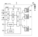
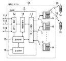
図1は、本実施形態に係る送受話システムの構成を示すブロック図である。本実施形態は、本発明を、いわゆる主装置と子機とを備えたボタン電話システムに適用した場合の実施形態である。 FIG. 1 is a block diagram showing a configuration of a transmission / reception system according to the present embodiment. This embodiment is an embodiment when the present invention is applied to a button telephone system including a so-called main device and a slave unit.
図1において、この電話システム1は、M本の電話回線11A〜11Mに接続された主装置(接続装置)2と、この主装置2に内線伝送路3を介して接続されたN個のボタン電話子機(非携帯型送受話装置)4A〜4Nを備えている。また図示するように、この電話システム1は、後述する無線伝送路を介してボタン電話機4Aに接続させる携帯電話機(携帯側送受話装置)5Aを利用する。
1, the telephone system 1 includes a main device (connection device) 2 connected to
主装置2は、外線I/F部12と、内線I/F部13と、交換処理部14と、主制御部15と、主記憶装置16とを備えている。
The
外線I/F部12は電話回線11A〜11Mを終端制御する回路部である。内線I/F部13は内線伝送路3を介してボタン電話子機4A〜4Nを収容する回路部である。交換処理部14は外線I/F部12と内線I/F部13とを交換接続する回路部である。
The external line I /
主制御部15は電話回線11A〜11Mおよびボタン電話子機4A〜4Nの状態を管理して装置全体を制御する機能部である。主記憶装置16は主制御部15での制御に必要な各種制御情報やプログラム等を記憶する回路部である。
The
特に、主制御部15は、CPUなどのマイクロプロセッサを有し、主記憶装置16に格納されているプログラムを読み込んで実行することにより、上記のハードウェアと協働して携帯経由外線交換手段としての機能を実現し、各種呼制御のほか電話システムの各種管理処理を行う。
In particular, the
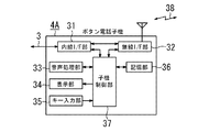
図2は、ボタン電話子機4A(4B〜4N)の構成例を示すブロック図である。ボタン電話子機4Aは、内線I/F部31、無線I/F部32、音声処理部33、表示部34、キー入力部35、記憶部36、子機制御部37を備えている。
FIG. 2 is a block diagram showing a configuration example of the
内線I/F部31は、内線伝送路3を介して主装置2とデータ伝送を行う回路部である。無線I/F部32は、無線伝送路38を介して携帯電話機5Aとデータ通信を行う回路部である。音声処理部33は、ボタン電話子機4Aで受話器を用いずに通話を行うためのスピーカホン機能や各種報知音の生成機能を有する回路部である。
The extension I /
表示部34は、データ伝送で主装置2から受け取った指示に基づきLED(Light Emitting Diode)やLCD(Liquid Crystal Display)を制御して各種表示を行う回路部である。キー入力部35は、利用者によるキー操作を検出する回路部である。記憶部36は、子機制御部37での処理動作に用いる各種情報やプログラムを記憶するメモリである。子機制御部37は、CPUなどのマイクロプロセッサを有し、記憶部36に格納されているプログラムを読み込んで実行することにより、上記ハードウェアと協働して無線接続手段および携帯経由外線接続手段としての機能を実現し、ボタン電話子機4Aの各部を制御する機能部である。
The
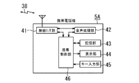
図3は、この電話システムに利用する携帯電話機の構成例を示すブロック図である。携帯電話機5Aは、無線I/F部41、音声処理部42、記憶部43、表示部44、キー入力部45、携帯制御部46を備えている。
FIG. 3 is a block diagram showing a configuration example of a cellular phone used in this telephone system. The
無線I/F部41は、無線伝送路38を介してボタン電話子機4Aとデータ通信を行う回路部である。音声処理部42は、スピーカやマイク(図示せず)を用いた音声通話機能や各種報知音の生成機能を有する回路部である。
The wireless I /
記憶部43は、携帯電話機5Aでの処理動作に用いる各種情報やプログラムを記憶するメモリである。表示部44は、データ通信でボタン電話子機4Aから受け取った指示に基づきLEDやLCDを制御して各種表示を行う回路部である。キー入力部45は、利用者によるキー操作を検出する回路部である。携帯制御部46は、CPUなどのマイクロプロセッサを有し、記憶部43に格納されているプログラムを読み込んで実行することにより、上記ハードウェアと協働して携帯電話5Aの各部を制御する機能部である。
The
この携帯電話機5Aは、一般的な無線電話回線を介して外線接続が可能である市販の携帯電話機であって、上記ボタン電話子機4A〜4Nの無線接続手段と協働してそれぞれ無線伝送路を形成し、ボタン電話機子機4A〜4Nとデータ通信できるものであればよい。そしてボタン電話子機4A〜4Nの無線接続手段は、そのボタン電話機を第1のボタン電話子機として所定の携帯電話機との間に無線伝送路を形成できるよう、予めその所定の携帯電話機を登録しておくことが必要であり、また携帯電話機も第1ボタン電話子機と対応するよう設定しておく必要がある。なお、この無線接続手段および無線伝送路の具体的形態の一例として Bluetooth などがある。もちろんこの携帯電話機5Aは、一般的な無線電話回線を介して外線接続できるものであれば、本発明の電話システムの一部として構成する専用機であってもよい。
The
また内線伝送路3は、電気信号を伝送可能な導体金属線であり、有線伝送路を構成している。
The
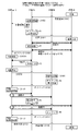
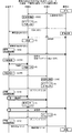
図4は、上記主装置2の主制御部15、子機4Aの制御部37、及び携帯電話機5Aの制御部46の協働により実行される制御動作を表す動作フローであり、電話システム1において、主装置2とボタン電話子機4A〜4Nとの間に1通話分の伝送路が用意されている場合の動作について説明する。なお、この図4では、典型的な例として、例えば自分の机のある部屋と他の研究室とを頻繁に往来する技術者に対して、外部の取引先がその技術者の携帯電話機(携帯電話機5A)へ直接呼び出し、技術者がその外線通話を携帯電話機5Aを経由して自分の机の上のボタン電話子機(子機4A)で受けて通話し、その後に他のボタン電話子機(子機4B)へその外線通話を転送する場合を例に取っている。
FIG. 4 is an operation flow showing a control operation executed by the cooperation of the
携帯電話機5Aが、一般無線電話回線を介して外部からの呼出を着信すると、無線伝送路38が形成され、この無線伝送路38を介し子機4Aに着信が通知される(ステップS101)。子機4Aは、この着信通知に応じて着信音を鳴らし(ステップS102)、主装置2に対して内線伝送路3を介して子機4Aが使用中であることを通知する(ステップS103)。これは、主装置2と子機4A、子機4Bとの間に1通話分の伝送路しか用意していないために行う処理であり、このように主装置2に対して子機使用中通知を行うことで、主装置2は他の外部からの呼出を禁止する。
When the
そして技術者が子機4Aの受話器を取り(オフフック動作、操作P1)、子機4Aが無線伝送路38を介して携帯電話機5Aに接続され、応答可能となる(ステップS104)。以上までの動作により、技術者は子機4Aの受話器を用いて外部の取引先との通話を開始することができる。
Then, the engineer picks up the handset of
そして、技術者が他の子機4Bへこの外線通話を転送する場合、子機4Aの保留ボタンを押すなどにより通話保留すると(操作P2)、子機4Aより無線伝送路38を介し外線通話に保留メロディー用のメロディー指令信号が送出される(ステップS105)。なおこのメロディー指令信号は、携帯電話機5Aにて音源及びメロディーファイルもすべて準備された状況で子機4Aより単なる演奏開始指示の信号を送るようにしてもよいし、携帯電話機5Aで音源のみが準備された状態で子機4AよりMIDIデータのようなメロディーファイル信号を送るようにしてもよいし、子機4Aよりメロディーそのものを送るようにしてもよい。
When the engineer transfers the external line call to the
その後、子機4Aは内線伝送路3を介して主装置2に対しオフフック動作を通知(ステップS106)すると、これに応じて主装置2が内線を回線捕捉し(ステップS107A)、これによって内線伝送路3を介して子機4Aとの間に内線ダイヤル回線(内線DT)が開かれる。この状態で子機4Aより子機4Bに対応する内線番号がダイヤルされると(操作P3)、主装置2がそれを受けて子機4Bに対し内線伝送路3を介して呼び出しをかける(ステップS107B)。
Thereafter, when the
子機4Bはその呼び出しに応答して呼び出し音を鳴らし(ステップS108)、子機4Bにて受話器が取られる(オフフック動作、操作P4)ことで子機4Bは主装置2に対してオフフック動作を通知する(ステップS109)。主装置2はこの着信応答を受けて、子機4Aと子機4Bとの間に内線伝送路の回線が開くよう交換接続し(ステップS110)、この結果、子機4Aと子機4Bとの間で内線通話が行われる。以上の操作P2からステップS110までの動作により、技術者は子機4Bの使用者に対して内線通話により、外部からの外線通話を転送する旨を伝えることができる。
In response to the call,
以上のようにして子機4A〜内線伝送路3〜主装置2〜内線伝送路3〜子機4Bの経路で子機4Aと子機4Bとが主装置2を介し接続されている状態で、技術者が子機4Aの転送ボタンを押す(または受話器を置くオンフック動作)などによる転送操作を行う(操作P5)。すると、無線伝送路38を介し保留状態となっている携帯電話機5A〜無線伝送路38(保留)〜子機4A間の接続と、前述の子機4A〜内線伝送路3〜主装置2〜内線伝送路3〜子機4Bの経路の接続とが連結(接続)され、携帯電話機5A〜無線伝送路38〜子機4A〜内線伝送路3〜主装置2〜内線伝送路3〜子機4Bの形の切換接続が完成される。この結果、無線伝送路38及び内線伝送路3を介し上記の外線通話が子機4Bに接続される。これにより外部の取引先は、子機4Bの使用者との通話を開始することができ、外線通話の転送が完了する。なお、他の子機4A,4C〜4Nへ転送する場合も同様の手順を繰り返せばよい。
In the state in which the
そして外部の取引先との通話が終了し、子機4Bの受話器が置かれる(オンフック動作、操作P6)と、内線伝送路3を介し主装置2に対しオンフック動作が通知される(ステップS111)。主装置2はこれを受けて、それまで内線伝送路3に設定していた内線伝送路を開放し(ステップS112)、携帯電話機5Aと無線伝送路38を形成している子機4Aに対して終話通知が発せられる(ステップS113)。これを受けて子機4Aと携帯電話機5Aとの間の無線伝送路38が切断される(ステップS114)。以上により全ての動作を終了する。
Then, when the call with the external customer is finished and the handset of the
なお、上記の動作フローにおいて、制御信号の生成は上記主装置2の主制御部15、子機4Aの制御部37、及び携帯電話機5Aの制御部46でどのように分担してもよいし、さらにその生成した信号をどのように授受してもよく、結果として上記動作が実現されれば足りるものである。
In the above operation flow, the generation of the control signal may be shared in any way by the
以上説明したように、本実施形態によれば、携帯電話機5Aにかかってきた外線通話を、子機4A及び主装置2を介し、別のボタン電話子機4Bに転送することができるので、利便性を向上できる。また、携帯電話機5Aを移動可能な着信端末として電話システム1内に収容できることから、電話システム全体の利用形態の自由度を向上させることができる。
As described above, according to the present embodiment, an outside line call that has been made to the
次に、図5を参照して、本実施形態の変形例にかかる電話システムの動作について説明する。本変形例は、図1に示す上記第1実施形態の構成と同じ構成で実現されるものであり、主装置2とボタン電話子機4A〜4Nとの間に2通話分の伝送路が用意されている場合のものである。
Next, the operation of the telephone system according to the modification of the present embodiment will be described with reference to FIG. This modification is realized by the same configuration as that of the first embodiment shown in FIG. 1, and a transmission path for two calls is prepared between the
図5は、図4の場合と同じ状況で外線通話を受け、転送する場合を例にとって示す、上記主装置2の主制御部15、子機4Aの子機制御部37、及び携帯電話機5Aの制御部46の協働により実行される制御動作を表す動作フローである。なお、図5に示す動作は、図4に示すステップS101からステップS106までの動作で相違するものであり、その他の同じ動作には図4のステップと同じ番号を付して説明を省略し、以下この相違する動作だけ説明する。
FIG. 5 shows an example of receiving and transferring an outside line call in the same situation as in FIG. 4, and the
携帯電話機5Aが、一般無線電話回線を介して外部からの呼出を着信すると、携帯電話機5Aと子機4Aとの間に無線伝送路38が形成され、子機4Aに着信が通知される(ステップS201)。子機4Aは、この着信通知に応答して着信音を鳴らし(ステップS202)、技術者が子機4Aの受話器を取ると(オフフック動作、操作P1)、無線伝送路38を介し子機4A側にて応答通話可能となる(ステップS203)。その後、主装置2に対して内線伝送路3を介して携帯が通話中であることが通知される(ステップS204)。これは、主装置2と子機4A、子機4Bとの間に2通話分の伝送路しか用意していないために行う処理であり、このように主装置2に対して子機使用中通知を行うことで、主装置2は他の外部からの呼出を禁止する。なお、3通話以上分の伝送路を用意した場合にはこの処理は不要である。以上までの動作により、技術者は子機4Aの受話器を用いて外部の取引先との通話を開始することができる。
When the
そして、技術者が他の子機4Bへこの外線通話を転送する場合、子機4Aの保留ボタンを押すなどにより通話保留すると(操作P2)、子機4Aより内線伝送路3を介して主装置2に対し携帯保留状態が通知され(ステップS205)、主装置2によって保留伝送路が接続確保される(ステップS206)。そして、主装置2は内線伝送路3と無線伝送路38を介して外線通話に保留メロディー用のメロディー指令信号(信号内容は上記実施形態と同じ)を送出する(ステップS207)。その後は図4に示すステップS107A以降と同じ動作を行うことにより同様の転送動作を行うことができる。
When the engineer transfers this outside line call to another
このように、本変形例によっても、上記第1実施形態と同様に外線通話を受け、転送することができる。またこれに加え、本変形例によれば、保留メロディー指令信号を主装置2より送出するので、例えばメロディー指令信号が前述のMIDIデータ等のメロディーファイル信号やメロディーそのものの信号である場合にその格納のために必要な比較的大容量のメロディーバンクは、主装置のみが保有していればよい。したがって、各ボタン電話子機がそれぞれメロディーバンクを備えることが必要となる第1実施形態に比べれば、機器負担を大幅に低減することができ、コストを低減できる。これは、内線伝送路に2通話分の伝送路が用意されているため、主装置からの保留メロディーの送出に利用する分と、それと同時に内線通話するための分とを確保できることによるものである。
As described above, according to the present modification, it is possible to receive and transfer an outside line call as in the first embodiment. In addition, according to the present modification, the hold melody command signal is transmitted from the
なお、上記第1の実施形態では、ボタン電話子機どうしの転送方法として主装置を介した転送方法を説明したが、それに限られずに、他にもボタン電話子機どうしで Bluetooth の無線伝送路により直接転送する方法や、ボタン電話子機から他の Bluetooth 端末へ転送する方法も実現する可能性がある。 In the first embodiment, the transfer method via the main unit has been described as the transfer method between the button telephone slave units. However, the present invention is not limited to this, and other Bluetooth wireless transmission paths between the button phone slave units are also possible. There is also a possibility of realizing a method of transferring directly from the phone or a method of transferring from a key phone handset to another Bluetooth terminal.
本発明の第2の実施形態を図6を用いて説明する。本実施形態も、本発明を、いわゆる主装置と子機とを備えたボタン電話システムに適用した場合の実施形態であり、1つのボタン電話子機4Aで2つの携帯電話機5A,5Bに対応し、それらの間の外線通話の転送もボタン電話子機4Aによって行うものである。
A second embodiment of the present invention will be described with reference to FIG. This embodiment is also an embodiment in the case where the present invention is applied to a button telephone system having a so-called main device and a slave unit, and one button
図6は、本実施形態に係る電話システム51の構成を示すブロック図である。この図6において、上記第1実施形態と構成上相違する大きな点は、1つのボタン電話子機(非携帯型送受話装置)4Aに2つの携帯電話機5A(第1携帯型送受話装置),5B(第2携帯型送受話装置)が対応する点である。図2、図3に示す他の構成については共通している。
FIG. 6 is a block diagram showing a configuration of the
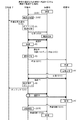
図7は、本実施形態の電話システム51における上記主装置2の主制御部15、子機4Aの制御部37、及び携帯電話機5Aの制御部46の協働により実行される制御動作を表す動作フローであり、前述の図4と同等の図である。図7においては、図4の場合における子機4Bが携帯電話機5Bに置き換わり、その他は図4の場合と同じ状況で外線通話を受け、転送する場合の電話システム51の動作を示している。
FIG. 7 shows an operation representing a control operation executed by the cooperation of the
図7において、図4に示すステップS105までの動作は同じであってステップS106以降の動作で相違するものであり、以下この相違する動作だけ説明する。 In FIG. 7, the operations up to step S105 shown in FIG. 4 are the same and are different in the operations after step S106. Only the different operations will be described below.
子機4Aの子機制御部37と携帯電話機5Bとの間に無線伝送路38が形成され、この無線伝送路38を介し携帯電話機5Bへと呼び出しがかけられる(ステップP3′)と、これによる呼び出し通知(ステップS311)が携帯電話機5Bで受信されて着信される。そして、携帯電話機5Bにて着信ボタンが押されるなどにより着信応答が可能となり(操作P4′)、携帯電話機5Bより子機4Aに対して応答動作が通知される(ステップS312)。この通知を受けて、子機4Aと携帯電話機5Bとの間で無線伝送路38を介し内線通話が可能となる。以上の動作により、技術者は携帯電話機5Bの使用者に対して内線通話により、外部からの外線通話を転送する旨を伝えることができる。
When a
以上のようにして携帯電話機5B〜無線伝送路38〜子機4Aの経路で携帯電話機5Bと子機4Aとが接続されている状態で、技術者が子機4Aの転送ボタンを押す(または受話器を置くオンフック動作)などによる転送操作を行う(操作P5′)。すると、無線伝送路38を介し保留状態となっている携帯電話機5A〜無線伝送路38(保留)〜子機4A間の接続と、前述の子機4A〜無線伝送路38〜携帯電話機5Bの経路の接続とが連結(接続)され、携帯電話機5A〜無線伝送路38〜子機4A〜無線伝送路38〜携帯電話機5Bの形の切換接続が完成される。この結果、携帯電話機5Aにかかってきた上記外線通話に対し無線伝送路38を介して携帯電話機5Bが接続される。また、子機4Aより主装置2に対して内線伝送路3を介しオンフック通知が発せられる(ステップS313)。以上の動作により外部の取引先は、携帯電話機5Bの使用者との通話することが可能となり、外線通話の転送が完了する。
As described above, the technician presses the transfer button of the
そして外部の取引先との通話が終了した場合には、携帯電話機5Bで通話中止ボタンを押すなどにより終話操作(操作P6′)をすることで、子機4Aとの間の無線伝送路38が切断され(ステップS314)、これによって子機4A側では通話開放状態とされて(ステップS315)携帯4Aとの間の無線伝送路38が切断される(ステップS316)。以上により全ての動作を終了する。
When the call with the external business partner is terminated, the end of the call operation (operation P6 ') is performed by pressing the call stop button on the
このように、本実施形態によれば、携帯電話機5Aにかかってきた外線通話を、子機4Aを介し、別の携帯電話機5Bに転送することができるので、利便性を向上できる。また、第1の実施形態と同様、携帯電話機5A、5Bをともに移動可能な着信端末および転送先端末としてシステムに収容でき、電話システム全体の利用形態の自由度をさらに向上させることができる。
As described above, according to the present embodiment, an outside line call that has been placed on the
以上は、本発明の送受話システムを、主装置2及びこれに有線の通信回線を介し接続された複数の子機4A〜4Nを備えたボタン電話システムに適用した場合を例にとって説明したが、これ以外の送受話システムに適用してもよい。
In the above, the transmission / reception system according to the present invention has been described by taking as an example a case where the transmission / reception system of the present invention is applied to a key telephone system including a
すなわち例えば、有線の通信回線に接続された有線電話機(いわゆる家庭電話の親機)及びこれに無線接続通信を介し接続された無線電話機(いわゆる家庭電話の子機)とを備えた家庭用電話機システムに適用してもよい。またさらに、本発明は、携帯型送受話装置、及びこれにリンクした非携帯型送受話装置を備える送受話システムであれば、上記ボタン電話システム、家庭用電話機システム以外の電話システムや、さらには電話以外の通信システムに対しても適用可能である。 That is, for example, a home telephone system including a wired telephone connected to a wired communication line (so-called home phone master unit) and a wireless phone connected to this via a wireless connection communication (so-called home phone slave unit). You may apply to. Still further, the present invention provides a portable transmission / reception device and a transmission / reception system including a non-portable transmission / reception device linked to the portable telephone transmission / reception device, a telephone system other than the button telephone system and the home telephone system, and The present invention can also be applied to communication systems other than telephones.
1,51・・・電話システム(送受話システム)、2・・・主装置、3・・・内線伝送路、4A・・・ボタン電話子機、4B・・・ボタン電話子機、5A・・・携帯電話機、5B・・・携帯電話機、38・・・無線伝送路。
DESCRIPTION OF
Claims (5)
この携帯型送受話装置に着信があったときにその着信に対し応答通話可能となるように無線接続通信を介し関連づけられた第1非携帯型送受話装置と、
この第1非携帯型送受話装置と別に設けられた第2非携帯型送受話装置と、
有線電話回線に接続され、この有線電話回線と前記第1及び第2非携帯型送受話装置との間を接続可能な接続装置と、
前記第1非携帯型送受話装置にて前記応答通話を行った前記携帯型送受話装置の前記着信に対し、前記第2非携帯型送受話装置より応答通話可能となるように、前記接続装置を切換接続する第1切換接続手段と
を有することを特徴とする送受話システム。 A portable transmission / reception device having a transmission / reception function via wireless communication;
A first non-portable handset that is associated via wireless connection communication so that a response call can be made to the incoming call when there is an incoming call to the portable handset;
A second non-portable transmitter / receiver provided separately from the first non-portable transmitter / receiver;
A connection device connected to a wired telephone line and capable of connecting the wired telephone line and the first and second non-portable handset devices;
The connection device so that a response call can be made from the second non-portable handset device to the incoming call of the portable handset device that has made the response call at the first non-portable handset device. And a first switching connection means for switching connection.
前記第1切換接続手段は、
前記携帯型送受話装置の着信に応答通話を行った前記第1非携帯型送受話装置と前記接続装置との間を第1内線伝送路で接続するとともに、前記接続装置と前記第2非携帯型送受話装置との間を第2内線伝送路で接続するように、前記接続装置を切換接続することを特徴とする送受話システム。 The transmission / reception system according to claim 1,
The first switching connection means is
The first non-portable handset device that has made a response call to the incoming call of the portable handset device and the connection device are connected by a first extension transmission path, and the connection device and the second non-portable device. A transmission / reception system, wherein the connection device is switched and connected so as to be connected to the type transmission / reception device via a second extension transmission line.
前記第1切換接続手段が、前記第1非携帯型送受話装置にて前記応答通話を行った前記携帯型送受話装置の前記着信を、前記第2非携帯型送受話装置より応答通話可能となるように切り換える際、前記携帯型送受話装置にて保留メロディーを鳴動させるためのメロディー指令信号を生成する信号生成手段を有することを特徴とする送受話システム。 In the transmission / reception system according to claim 1 or 2,
The first switching connection means is capable of answering a call from the second non-portable transmitter / receiver for the incoming call of the portable transmitter / receiver that has made the response call at the first non-portable transmitter / receiver. A transmission / reception system comprising signal generation means for generating a melody command signal for sounding a held melody in the portable transmission / reception device when switching is performed.
前記信号生成手段は前記接続装置に備えられており、生成した前記メロディー指令信号を前記第1非携帯型送受話装置を介して前記携帯側送受話装置へ送信することを特徴とする送受話システム。 The transmission / reception system according to claim 3,
The signal generating means is provided in the connection device, and transmits the generated melody command signal to the portable-side transmitter / receiver device via the first non-portable transmitter / receiver device. .
少なくとも前記第1携帯型送受話装置に着信があったときにその着信に対し応答通話可能となるように、前記第1及び第2携帯型送受話装置に無線接続通信を介し関連づけられた非携帯型送受話装置と、
この非携帯型送受話装置にて前記応答通話を行った前記第1携帯型送受話装置の前記着信に対し、前記第2携帯型送受話装置より応答通話可能となるように、前記第1携帯型送受話装置、前記非携帯型送受話装置、前記第2携帯型送受話装置を切換接続する第2切換接続手段と
を有することを特徴とする送受話システム。 First and second portable transmission / reception devices each having a transmission / reception function via wireless communication;
A non-portable that is associated with the first and second portable handset devices via wireless connection communication so that at least when the first portable handset device receives an incoming call, a response call can be made to the incoming call. Type transmitter / receiver,
The first mobile phone is configured so that a response call can be made from the second portable handset device to the incoming call of the first portable handset device that has made the answer call by the non-portable handset device. A transmission / reception system comprising a type transmission / reception device, the non-portable transmission / reception device, and a second switching connection means for switching connection of the second portable transmission / reception device.
Priority Applications (1)
| Application Number | Priority Date | Filing Date | Title |
|---|---|---|---|
| JP2004103618A JP2005294969A (en) | 2004-03-31 | 2004-03-31 | Transceiver system |
Applications Claiming Priority (1)
| Application Number | Priority Date | Filing Date | Title |
|---|---|---|---|
| JP2004103618A JP2005294969A (en) | 2004-03-31 | 2004-03-31 | Transceiver system |
Publications (1)
| Publication Number | Publication Date |
|---|---|
| JP2005294969A true JP2005294969A (en) | 2005-10-20 |
Family
ID=35327459
Family Applications (1)
| Application Number | Title | Priority Date | Filing Date |
|---|---|---|---|
| JP2004103618A Pending JP2005294969A (en) | 2004-03-31 | 2004-03-31 | Transceiver system |
Country Status (1)
| Country | Link |
|---|---|
| JP (1) | JP2005294969A (en) |
Cited By (1)
| Publication number | Priority date | Publication date | Assignee | Title |
|---|---|---|---|---|
| JP2008092189A (en) * | 2006-09-29 | 2008-04-17 | Saxa Business System Inc | Key telephone system |
-
2004
- 2004-03-31 JP JP2004103618A patent/JP2005294969A/en active Pending
Cited By (1)
| Publication number | Priority date | Publication date | Assignee | Title |
|---|---|---|---|---|
| JP2008092189A (en) * | 2006-09-29 | 2008-04-17 | Saxa Business System Inc | Key telephone system |
Similar Documents
| Publication | Publication Date | Title |
|---|---|---|
| US6018665A (en) | Wireless terminal with auxilary desktop unit | |
| CN101304449B (en) | Integration type communication equipment | |
| CN201608742U (en) | Intelligent fixed phone | |
| JPH07250376A (en) | Cordless terminal control system | |
| US20180316798A1 (en) | Communication system, communication method, and communication adapter | |
| CN102035907A (en) | Intelligent fixed-line telephone | |
| CN201042032Y (en) | integrated communication device | |
| CN101119399B (en) | Blue tooth loudspeaker | |
| JP3737273B2 (en) | Button telephone apparatus and incoming call reception method thereof | |
| JP2000165520A (en) | Call waiting (registered trademark) system and mobile terminal | |
| JP4258563B2 (en) | Telephone system | |
| JP4144650B2 (en) | Phone terminal | |
| JP3354614B2 (en) | Wireless telephone equipment | |
| JP4172025B2 (en) | Button telephone equipment | |
| JP3700553B2 (en) | Button telephone equipment | |
| JP4749272B2 (en) | Cordless telephone equipment | |
| JP3354966B2 (en) | Telephone system | |
| JPH04296125A (en) | telephone | |
| JP2008092189A (en) | Key telephone system | |
| KR20020057682A (en) | Method of building call in mobile communication terminal | |
| WO2001097492A1 (en) | Cradle for mobile communication terminal | |
| JP4258564B2 (en) | Telephone system, telephone control device, and program | |
| KR101106768B1 (en) | Multifunctional communication device using Bluetooth | |
| KR200165424Y1 (en) | Key-board phone for the computer | |
| JPH0479551A (en) | Telephone set |
Legal Events
| Date | Code | Title | Description |
|---|---|---|---|
| RD04 | Notification of resignation of power of attorney |
Free format text: JAPANESE INTERMEDIATE CODE: A7424 Effective date: 20051031 |
|
| A621 | Written request for application examination |
Free format text: JAPANESE INTERMEDIATE CODE: A621 Effective date: 20061030 |
|
| A977 | Report on retrieval |
Free format text: JAPANESE INTERMEDIATE CODE: A971007 Effective date: 20071214 |
|
| A131 | Notification of reasons for refusal |
Free format text: JAPANESE INTERMEDIATE CODE: A131 Effective date: 20080129 |
|
| A02 | Decision of refusal |
Free format text: JAPANESE INTERMEDIATE CODE: A02 Effective date: 20080603 |