JP2005294899A - Optical transmitter - Google Patents
Optical transmitter Download PDFInfo
- Publication number
- JP2005294899A JP2005294899A JP2004102533A JP2004102533A JP2005294899A JP 2005294899 A JP2005294899 A JP 2005294899A JP 2004102533 A JP2004102533 A JP 2004102533A JP 2004102533 A JP2004102533 A JP 2004102533A JP 2005294899 A JP2005294899 A JP 2005294899A
- Authority
- JP
- Japan
- Prior art keywords
- optical
- optical axis
- optical signal
- reception
- receiving
- Prior art date
- Legal status (The legal status is an assumption and is not a legal conclusion. Google has not performed a legal analysis and makes no representation as to the accuracy of the status listed.)
- Pending
Links
Images


Abstract
Description
本発明は、光無線伝送装置を構成する光送信機と光受信機との間の光軸を合わせる光送信機に関する。 The present invention relates to an optical transmitter for aligning an optical axis between an optical transmitter and an optical receiver constituting an optical wireless transmission apparatus.
従来から、光を用いて情報の空間伝送を行う光無線伝送技術がある。光無線伝送は一般的に赤外光が用いられ、その発光素子として発光ダイオードやレーザダイオードなどの半導体発光素子が用いられている。このような光無線伝送において、送受信間距離を十分にとりたい場合は、受信機側に十分な光レベルを入射させるように送信機から発する光ビームの指向角を鋭く絞る必要がある。この場合、送信機及び受信機の光軸を合わせておかなければならないが、指向角の狭い光ビームを用いることや光ビームに目に見えない赤外光を用いることなどから、光無線伝送装置の光軸合わせは大変煩わしい作業である。そこで、光軸合わせを容易に行えるような光無線伝送装置が下記の特許文献1に開示されている。この特許文献1に開示されている光無線伝送装置は、送信装置から可視光をピンポイントに絞って信号伝送用の赤外光と同一光軸、あるいは平行光軸にして一緒に送り、受信装置側に設けた可視光反射手段に当てるものであり、可視光反射手段により反射させられた可視光を操作者が見ながら送信装置の光軸調整を行う。また、この他の技術としては送信装置に照準機を設置して、その照準機を見ながら光軸を合わせる光無線伝送装置や、受信装置側に受光レベル検出用測定器を接続して二人一組で光軸合わせを行う光無線伝送装置もある。また、受光装置側に光軸調整用の光源を用いて、送信装置からの送信光の受信レベル情報を折り返し、それに応じて光軸を合わせるものが下記の特許文献2に開示されている。
しかしながら、特許文献1に開示された光無線伝送装置は、送信装置に光無線伝送の目的以外に使用する可視光を発生させる構成を必要としている。送受信装置間の距離を十分にとりたい場合などは、この可視光の発光出力を十分大きいものにしなくてはならず、またその構成を追加する必要があるため、送信装置のコストアップとなってしまう上、装置が大型になってしまうという問題がある。これは、送信装置に照準機を設置する場合も同様である。また、可視光の光軸や、照準機の照準と信号伝送用の赤外光の光軸とを厳密に合わせておく必要があることもコストアップの要因となる。また、受光レベル検出用測定器を受信装置に接続して二人一組で行う場合においても、受光レベル検出用測定器を用意する必要があり、人手を要するなどの欠点があった。このように、従来の光無線伝送装置は、光軸合わせを簡単化しようとすると、送受信装置のコストアップや大型化を招き、送受信装置のコストダウンや小型化を行おうとすると、光軸合わせの作業に手間がかかるなどの欠点を有していた。 However, the optical wireless transmission device disclosed in Patent Document 1 requires a configuration that causes the transmission device to generate visible light used for purposes other than optical wireless transmission. When a sufficient distance between the transmitting and receiving devices is desired, the visible light emission output must be made sufficiently large, and the configuration needs to be added, which increases the cost of the transmitting device. In addition, there is a problem that the apparatus becomes large. The same applies to the case where a sighting device is installed in the transmission device. In addition, it is necessary to precisely match the optical axis of visible light, the aiming of the sighting device, and the optical axis of infrared light for signal transmission. Further, even when the light receiving level detection measuring device is connected to the receiving device and performed by a pair of two people, it is necessary to prepare the light receiving level detecting measuring device, and there is a drawback that it requires manpower. As described above, the conventional optical wireless transmission device increases the cost and size of the transmission / reception device when trying to simplify the optical axis alignment, and reduces the optical axis alignment when trying to reduce the cost and size of the transmission / reception device. It had drawbacks such as time-consuming work.
また、特許文献2に開示された技術では、上述した問題点の解決を図っているが、受信機に取り付けられた光軸調整用の光送信素子からパイロット信号としての送信光を、送信機に搭載した単一の受光素子で受光し、その受光レベルと送信機からの信号伝送用の送信光の受信機での受信レベルのみを基準に光軸を調整している。このため、人がこの情報を基にレベル表示装置などを用いて光軸を調整する場合には十分その手間を簡単化することができるが、自動で光軸を調整する場合は不要な動作が多くなってしまう。その理由は、単純に単一の受光素子で得られる光軸調整用の送信光のレベルだけでは上下左右どちらに受信機が有るかを判別することはできない。そのため自動で光軸を調整するためには必ず一度やみくもに動かし、受光レベルと比較して自身の動いた方向が正しいかどうかを判定しなければならず、動いてみてから判断しなければならない。これでは、無駄な動きが多くなってしまい、メカ駆動に要する時間を考えると、高速な自動光軸合わせの足かせとなってしまうという問題がある。
Further, in the technique disclosed in
以上のようなことを考慮して、おおまかな(粗い)方向へ調整した後に、受信機から受信する送信機が送信した光信号に対する送達情報を基に光軸を合わせるという考えもある。特に、狭い指向角の送信光を用いる場合には、初期段階での粗い調整の精度が重要となってくる。しかしながら、実際の光無線伝送装置では、組み立て誤差や部品のばらつきなどから生じる光軸調整誤差や、外装や光フィルタが光送受信部の前面に取り付けられることによる外装などでの光信号の屈折による光軸調整誤差が発生し、特に送信光が狭い指向角である場合にはその影響は無視できず、光軸のずれによって送信が不能となってしまうケースも起こり得る。 In consideration of the above, there is also an idea of adjusting the optical axis based on the delivery information for the optical signal transmitted by the transmitter received from the receiver after adjusting in the rough (coarse) direction. In particular, when using transmission light with a narrow directivity angle, the accuracy of rough adjustment at the initial stage is important. However, in an actual optical wireless transmission device, optical axis adjustment errors caused by assembly errors and component variations, and light due to refraction of optical signals at the exterior of the exterior and the optical filter attached to the front of the optical transceiver An axis adjustment error occurs. In particular, when the transmitted light has a narrow directivity angle, the influence cannot be ignored, and there may be a case where transmission becomes impossible due to the deviation of the optical axis.
また、上述した受信機から送信される送達情報によって送信機が光軸調整をするものにおいても、送信機が送信中に動いてしまいわずかに光軸がずれてしまった場合、光軸を再調整する必要が生じるが、その際に、送信機はいずれの方向に送信機を動かせばよいかは送達情報のみで類推することは困難である。そのために、光軸の再調整を無作為に行いながら光軸の合う位置を探すようになり、必ずしも速やかに光軸の合う位置に復帰できるとは限らない。 Even if the transmitter adjusts the optical axis according to the delivery information transmitted from the receiver described above, the optical axis is readjusted if the transmitter moves during transmission and the optical axis slightly shifts. In this case, it is difficult to infer in which direction the transmitter should move the transmitter from the delivery information alone. For this reason, a position where the optical axes are matched is searched while the optical axes are readjusted at random, and it is not always possible to quickly return to the position where the optical axes are matched.
本発明は、上記問題を解決するためのものであり、狭い指向角の送信光を使用するような光無線伝送装置でも簡単に光軸合わせをすることが可能であり、使用中の光軸のずれにおいても速やかに再調整することができる光送信機を提供することを目的とする。 The present invention is for solving the above problems, and it is possible to easily align the optical axis even in an optical wireless transmission device that uses transmission light with a narrow directivity angle. An object of the present invention is to provide an optical transmitter that can quickly readjust even in the case of deviation.
上記目的を達成するために、本発明によれば、光受信機に対して送信手段から光送信する第1の光信号の光軸を調整する光送信機において、複数の受信素子によって構成され、前記光軸を調整するための第2の光信号を前記光受信機から受信する受信手段と、前記第2の光信号の光軸のずれを補正する際の基準となる補正係数を記憶する記憶手段と、前記受信手段の各前記受信素子によって受信された前記第2の光信号の受信レベルが所定の条件を満たしているか否かを判断する判断手段と、前記判断手段によって前記所定の条件を満たさないと判断された場合に、前記所定の条件を満たすように前記受信手段及び/又は前記送信手段の向きを調整し、また前記判断手段によって前記所定の条件を満たすと判断された場合であって、前記受信手段によって受信された前記第2の光信号に前記送信手段が送信した前記第1の光信号に対する受信エラーを示す受信エラーレート情報が含まれている場合に、前記受信エラーが無くなるように前記受信手段及び/又は前記送信手段の向きを調整し、光軸を合わせる調整手段とを備え、前記調整手段は、光軸が合わせられた後に前記光軸のずれが生じた際、前記記憶手段に記憶された前記補正係数、及び前記光軸のずれが生じた後に前記受信手段によって受信される前記第2の光信号の受信レベルに基づいて、前記受信手段及び/又は前記送信手段の向きを調整し、光軸を合わせることを特徴とする光送信機が提供される。ここで、所定の条件とは、例えば4つの受信素子(以下、受光素子とも言う)からなる受信手段が受信する第2の光信号の受信レベルのそれぞれが同一であることを言う。また、送信手段は、後述する第1の光送信手段9に相当するものである。 In order to achieve the above object, according to the present invention, an optical transmitter that adjusts the optical axis of a first optical signal that is optically transmitted from a transmitting unit to an optical receiver is constituted by a plurality of receiving elements, Receiving means for receiving a second optical signal for adjusting the optical axis from the optical receiver, and a memory for storing a correction coefficient serving as a reference when correcting a deviation of the optical axis of the second optical signal Means for determining whether or not the reception level of the second optical signal received by each receiving element of the receiving means satisfies a predetermined condition, and the predetermined condition is determined by the determining means. When it is determined that the predetermined condition is not satisfied, the direction of the reception unit and / or the transmission unit is adjusted so as to satisfy the predetermined condition, and the determination unit determines that the predetermined condition is satisfied. The reception When the second optical signal received by the stage includes reception error rate information indicating a reception error with respect to the first optical signal transmitted by the transmission means, the reception is performed so that the reception error is eliminated. And / or adjusting means for adjusting the orientation of the transmitting means and adjusting the optical axis, and the adjusting means stores in the storage means when the optical axis shifts after the optical axes are aligned. The direction of the receiving unit and / or the transmitting unit is adjusted based on the corrected correction coefficient and the reception level of the second optical signal received by the receiving unit after the optical axis shift occurs. An optical transmitter characterized by aligning the optical axes is provided. Here, the predetermined condition means that the reception levels of the second optical signals received by the receiving means including, for example, four receiving elements (hereinafter also referred to as light receiving elements) are the same. The transmission means corresponds to first optical transmission means 9 described later.
また、本発明によれば、光受信機に対して送信手段から光送信する第1の光信号の光軸を調整する光送信機において、複数の受信素子によって構成され、前記光軸を調整するための第2の光信号を前記光受信機から受信する受信手段と、前記第2の光信号の光軸のずれを補正する際の基準となる第1の補正係数を記憶する第1の記憶手段と、前記受信手段の各前記受信素子によって受信された前記第2の光信号の受信レベルが所定の条件を満たしているか否かを判断する判断手段と、前記判断手段によって前記所定の条件を満たさないと判断された場合に、前記所定の条件を満たすように前記送信手段及び/又は前記受信手段の向きを調整し、また前記判断手段によって前記所定の条件を満たすと判断された場合であって、前記受信手段によって受信された前記第2の光信号に前記送信手段が送信した前記第1の光信号に対する受信エラーを示す受信エラーレート情報が含まれている場合に、前記受信エラーが無くなるように前記送信手段及び/又は前記受信手段の向きを調整し、光軸を合わせる調整手段と、前記調整手段によって光軸が合わせられた際の前記第2の光信号の受信レベルの情報に基づいて、前記光軸のずれを補正する際の基準となる第2の補正係数を算出する算出手段と、前記算出手段によって算出された前記第2の補正係数を記憶する第2の記憶手段とを備え、前記調整手段は、光軸が合わせられた後に前記光軸のずれが生じた際、前記第2の記憶手段に前記第2の補正係数が記憶されている場合には、前記光軸のずれが生じた後に前記受信手段によって受信される前記第2の光信号の受信レベル及び前記第2の補正係数に基づいて前記第2の光信号の受信レベルを補正し、前記第2の記憶手段に前記第2の補正係数が記憶されていない場合には、前記受信手段によって受信される前記第2の光信号の受信レベル及び前記第1の記憶手段に記憶された前記第1の補正係数に基づいて前記第2の光信号の受信レベルを補正し、前記判断手段は、補正された前記第2の光信号の受信レベルが前記所定の条件を満たしているか否かを判断し、前記調整手段は、前記判断手段によって前記所定の条件を満たすと判断された場合、前記受信手段によって受信される前記第2の光信号に、前記所定の条件を満たすと判断された後に前記送信手段が送信した前記第1の光信号に対する受信エラーを示す受信エラーレート情報が含まれている場合に、前記受信エラーが無くなるように前記送信手段及び/又は前記受信手段の向きを調整し、光軸を合わせることを特徴とする光送信機が提供される。 According to the invention, in the optical transmitter that adjusts the optical axis of the first optical signal that is optically transmitted from the transmitting means to the optical receiver, the optical transmitter is configured by a plurality of receiving elements and adjusts the optical axis. Receiving means for receiving a second optical signal for receiving from the optical receiver, and a first storage for storing a first correction coefficient serving as a reference in correcting a deviation of the optical axis of the second optical signal Means for determining whether or not the reception level of the second optical signal received by each receiving element of the receiving means satisfies a predetermined condition, and the predetermined condition is determined by the determining means. When it is determined that the predetermined condition is not satisfied, the direction of the transmitting means and / or the receiving means is adjusted so as to satisfy the predetermined condition, and the predetermined condition is determined by the determining means. By the receiving means When the second optical signal received in this way includes reception error rate information indicating a reception error with respect to the first optical signal transmitted by the transmission unit, the transmission unit eliminates the reception error. And / or adjusting the direction of the receiving means to adjust the optical axis, and based on the information on the reception level of the second optical signal when the optical axis is adjusted by the adjusting means, the optical axis And a second storage means for storing the second correction coefficient calculated by the calculation means, the adjustment means comprising: If the second correction coefficient is stored in the second storage means when the optical axis shift occurs after the optical axes are aligned, the optical axis shift occurs after Received by the receiving means The reception level of the second optical signal is corrected based on the reception level of the second optical signal and the second correction coefficient, and the second correction coefficient is stored in the second storage means. If not, the reception level of the second optical signal based on the reception level of the second optical signal received by the reception unit and the first correction coefficient stored in the first storage unit The determination means determines whether or not the corrected reception level of the second optical signal satisfies the predetermined condition, and the adjustment means satisfies the predetermined condition by the determination means. If it is determined that the second optical signal is received, the second optical signal received by the receiving unit indicates a reception error with respect to the first optical signal transmitted by the transmitting unit after it is determined that the predetermined condition is satisfied. Receive error rate When information is included, an optical transmitter is provided that adjusts the direction of the transmission unit and / or the reception unit so as to eliminate the reception error and aligns the optical axis.
本発明の情報表示サーバは、上記構成を有し、狭い指向角の送信光を使用するような光無線伝送装置でも簡単に光軸合わせをすることが可能であり、使用中の光軸のずれにおいても速やかに再調整することができる。 The information display server of the present invention has the above-described configuration and can easily align the optical axis even in an optical wireless transmission device that uses transmission light with a narrow directivity angle. Can be readjusted promptly.
<第1の実施の形態>
以下、本発明の第1の実施の形態について図1から図9を用いて説明する。図1は、本発明の第1の実施の形態に係る光送信機と光受信機の構成を示す図である。図2は、本発明の第1の実施の形態に係る光送信機を含む光無線伝送装置を示す模式図である。図3は、本発明の第1の実施の形態に係る光送信機における光受信機の方向を検出する原理を説明するための図である。図4Aは、本発明の第1の実施の形態に係る光送信機における光受信機の方向を検出する原理を説明するための図である。図4Bは、本発明の第1の実施の形態に係る光送信機における光受信機の方向を検出するために用いられる受光レベルの関係を示す表である。図5は、本発明の第1の実施の形態に係る光送信機と光受信機との間の光軸のずれがない場合の光無線伝送装置について説明するための図である。図6は、本発明の第1の実施の形態に係る光送信機と光受信機との光軸のずれがある場合の光無線伝送装置について説明するための図である。図7は、本発明の第1の実施の形態に係る光送信機に外装がある場合の光軸のずれを説明するための図である。図8は、本発明の第1の実施の形態に係る光送信機の制御部の構成を示す図である。図9は、本発明の第1の実施の形態に係る光送信機における光軸調整の動作フローを示すフローチャートである。
<First Embodiment>
Hereinafter, a first embodiment of the present invention will be described with reference to FIGS. FIG. 1 is a diagram showing a configuration of an optical transmitter and an optical receiver according to the first embodiment of the present invention. FIG. 2 is a schematic diagram showing an optical wireless transmission apparatus including the optical transmitter according to the first embodiment of the present invention. FIG. 3 is a diagram for explaining the principle of detecting the direction of the optical receiver in the optical transmitter according to the first embodiment of the present invention. FIG. 4A is a diagram for explaining the principle of detecting the direction of the optical receiver in the optical transmitter according to the first embodiment of the present invention. FIG. 4B is a table showing a relationship between received light levels used to detect the direction of the optical receiver in the optical transmitter according to the first embodiment of the present invention. FIG. 5 is a diagram for explaining the optical wireless transmission apparatus when there is no deviation of the optical axis between the optical transmitter and the optical receiver according to the first embodiment of the present invention. FIG. 6 is a diagram for explaining the optical wireless transmission device when there is a deviation of the optical axis between the optical transmitter and the optical receiver according to the first embodiment of the present invention. FIG. 7 is a diagram for explaining a deviation of the optical axis when the optical transmitter according to the first embodiment of the present invention has an exterior. FIG. 8 is a diagram illustrating a configuration of a control unit of the optical transmitter according to the first embodiment of the present invention. FIG. 9 is a flowchart showing an operation flow of optical axis adjustment in the optical transmitter according to the first embodiment of the present invention.
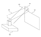
まず、本発明の第1の実施の形態に係る光送信機を含む光無線伝送装置について図2を用いて説明する。光無線伝送装置は、映像制御装置53に設置された光送信機1から光無線により伝送されるデジタル映像信号データを、映像表示装置54側に設置された光受信機16によって受信し、映像表示装置54に映像を表示させるものである。ここで、映像表示装置54は、例えばプラズマ・ディスプレイ・パネル(PDP)テレビのような高品位表示装置である。また、映像制御装置53は、例えばチューナーである。
First, an optical wireless transmission apparatus including the optical transmitter according to the first embodiment of the present invention will be described with reference to FIG. The optical wireless transmission device receives the digital video signal data transmitted by optical wireless from the optical transmitter 1 installed in the
光無線伝送装置は、光送信機1から放たれる第1の光送信信号(以下送信光とも言う)40によって光受信機16へデータを伝送するものであり、限られた光パワーで効率的にデータを伝送するために、送信光40は狭い送信指向角度において行うものであり、送信光40を光受信機16へ正確に当てることが重要な伝送条件となっている。このことから、送信光40を光受信機16へ合わせることが要求される光無線伝送装置では光軸調整という概念(機能)が求められる。さらに、光送信機1はチューナーなどの映像制御装置53側に設置されるため、実用上、日常生活での衝撃、例えば掃除などによっても位置(光軸)がずれてしまうこともあり、そのたびにユーザが精密な光軸調整を行うことは、使用快適度を著しく妨げるものである。そこで、光送信機1には自動的に光軸を調整する機能があることが望ましく、使用中に光軸のずれが生じても、速やかに自動的に光軸を再調整できることが望ましい。また、このような光送信機1に自動光軸調整機能を持たせるためには、光受信機16側に、光送信機1が光軸を調整するための第2の光送信信号、例えばパイロット光41を放射する手段が装備されることになる。
The optical wireless transmission apparatus transmits data to the
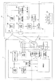
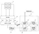
次に、本発明の第1の実施の形態に係る光送信機及び光受信機の構成について図1を用いて説明する。まず、光受信機16の構成について説明する。光受信機16では、光送信機1の第1の光送信手段9によって空間伝送される第1の光送信信号40を受光するための、比較的広い指向角の第1の光受信手段17が第1の光送信信号40を受信し、受光回路18が受信した第1の光送信信号40に電気的に増幅するなどの処理をし、二値化回路19が増幅された第1の光送信信号40をデジタル信号化し、シンボル復号回路21が復号化を行い、不図示の受像装置などの外部装置へ送信する。ここで、第1の光受信手段17は、例えばPD(Photo Diode)、APD(Advanced Photo Diode)、集光レンズなどで構成されたものである。また、シンボル復号回路21は、例えば10B8B変換回路である。
Next, the configuration of the optical transmitter and the optical receiver according to the first embodiment of the present invention will be described with reference to FIG. First, the configuration of the
また光受信機16では、光送信機1が光軸を調整するために広い指向角を有する第2の光送信手段29が、光送信機1に対して第2の光送信信号41を送信する。ここで、第2の光送信手段29は、例えばLED(Light Emitting Diode)又はLEDにレンズを加えたものである。また、第2の光送信信号41は、例えばパイロット光である。さらに、第2の光送信手段29は、第1の光受信手段17で受信した第1の光送信信号40に対する受信エラーを示す受信エラーレート情報を送信する機能も兼ね備えており、光受信機16では、第1の光受信手段17で受信され、二値化回路19でデジタル化された第1の光送信信号40のエラー検出を行っている。このエラー検出にシンボルエラー検出回路24が用いられている。ここで検出されるエラーをエラーレート算出回路25が一定時間監視(カウント)し、その結果を第2の光送信手段29で伝送するためにエラーレートパケット生成回路26がパケット化し、変調回路27がパケットに応じて変調を加え、発光素子ドライバ28に送る。これにより、第2の光送信手段29を用いて、光送信機1から送信されてくる第1の光送信信号40の受信状況を光送信機1に送っている。
In the
また、光受信機16において受信された第1の光送信信号40のエラー検出をする際に、第1の光送信信号40を一定レベル以上で受信していない場合には、エラーの検出を見合わせるために、信号レベル検出回路20は、第1の光受信手段17及び受光回路18で受けた光信号の受信レベルを監視し、エラーレートパケットの発生を停止させる。
In addition, when detecting the error of the first
次に、本発明の第1の実施の形態に係る光送信機について説明する。光送信機1では、不図示の外部のデータ発生機器から送られる映像信号などの信号を受信し、その信号を符号化回路2が符号化し、符号化された信号を二値化回路3が光送信可能な二値化デジタル信号に変換し、発光素子ドライバ4へ送る。発光素子ドライバ4は、二値化された信号を光伝送するために第1の光送信手段9をドライブして、指向角の狭い送信光として光受信機16へデータを空間伝送する。ここで、符号化回路2は、例えば8B10B変換回路である。また、第1の光送信手段9は、例えばLEDやLD(Laser Diode)、集光レンズなどで構成されたものである。
Next, an optical transmitter according to the first embodiment of the present invention will be described. In the optical transmitter 1, a signal such as a video signal transmitted from an external data generator (not shown) is received, the signal is encoded by the
また、光送信機1には、光受信機16の光軸調整用に搭載された第2の光送信手段29によって送信される第2の光送信信号41を受信するための第2の光受信手段10が存在する。ここで、第2の光受信手段10は、例えば複数の受光素子で構成されている。受光回路11は、各受光素子で受信された受信信号を電気的に増幅させるなどの処理を加える。この受光回路11によって処理された受信信号を制御部5が信号セレクト回路12を用いて特定の受信信号のみを選択し、受信レベル検出回路15がその受信レベルを検出し、制御部5へその結果を引き渡す。さらに、制御部5によって信号セレクト回路12で選択される受信信号は、復調回路13で復調し、光受信機16側での第1の光送信信号40の受信エラーレート情報を得るために、パケット検出・解析手段14が光受信機16からの受信エラーレート情報を検出し、その結果を制御部5へ送る。
Further, the optical transmitter 1 receives the second optical reception signal for receiving the second
ここで、制御部5は、光送信機1の光軸を光受信機16へ合わせるために適時、信号セレクト回路12を用いて必要な第2の光受信手段10による受信信号を選択し、受信レベル検出回路15や光受信機16から送られてくる受信エラーレート情報をパケット検出・解析手段14によって得て、これらの情報を基に駆動制御部6を制御し、駆動手段7、8を制御し、第1の光送信手段9及び第2の光受信手段10の向きを調整する。また、制御部5は、受信レベル検出回路15からの情報を基に、第1の光送信信号40が光軸合わせ中に不用意に周辺に放出することを防止するように発光素子ドライバ4を制御している。ここで、制御部5は、例えばMPUやDSP(Digital Signal Processor)などである。また、駆動手段7、8は、例えばステッピングモータなどである。
Here, the
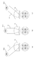
次に、上述した図2のような第2の光送信手段29によって発光される第2の光送信信号41をパイロット光として、光送信機1が第2の光受信手段10を用いて光受信機16の方向を検出する基本的原理の一例を図3、図4A及び図4Bの表を用いて説明する。まず、ここでは、光送信機1が備える第2の光受信手段10が図3に示すような4個のPD素子からなり、それらが1つのレンズで封入された場合について説明する。図3に示すように、4分割PDは、4つのPD1、PD2、PD3、PD4が1つの光学レンズの中に収められている。この素子は、光の入射方向によって各受光素子PD1、PD2、PD3、PD4の受光レベル(以下、受信レベルとも言う)が変化するものであり、図3ではその原理を3つのパターン(a)、(b)、(c)に分けて示している。
Next, the second
図3の(a)の場合は、4分割PDに対して光源300が左側(PD1及びPD3側)に位置している場合であり、この場合には各PDが封入されるレンズによって入射光はPD2及びPD4側へ集光することになり、その結果として各受光レベルの関係はPD1<PD2、PD3<PD4となる。図3の(b)の場合は、光源300が4分割PDの正面に位置する場合であり、この場合は各PDの位置する中央に集光されるため、各受光レベルの関係は、PD1=PD2、PD3=PD4となる。図3の(c)の場合は、4分割PDに対して光源300が右側(PD2、PD4側)に位置している場合であり、この場合には各PDが封入されるレンズによって入射光はPD1及びPD3側へ集光することになり、その結果として各受光レベルの関係は、PD1>PD2、PD3>PD4となる。
In the case of FIG. 3A, the
このことから、4分割PDのような受光素子の特性を利用して光源300の位置する方向を受光素子の各受光レベルを比較することで知ることができる。このことを利用して方向合わせについての動作の一例を図4A及び図4Bの表を用いて説明する。図4Aには、光送信機1が搭載する受光素子PD1、PD2、PD3、PD4からなる第2の光受信手段10が示されており、第2の光受信手段10から見て光受信機16がどこにあるかを示したものである。なお、図4A中では、光受信機16の位置を第2の光送信手段29の位置として「光源」として表記している。
From this, it is possible to know the direction in which the
ここで、光送信機1から見て図4Aに示す光源300の位置Aの方向に光受信機16がある場合、光送信機1の第2の光受信手段10のPD1の受信レベルをSL1、PD2の受信レベルをSL2、PD3の受信レベルをSL3、PD4の受信レベルをSL4とすると、図4Bの表に示すようにおおよそSL1=SL2<SL3=SL4という関係になる。このことから、制御部5は、これら第2の光受信手段10から得られる受信レベルを比較し、SL1=SL2<SL3=SL4の関係から光受信機16が上方向にあると判断し、駆動制御部6に第1の光送信手段9及び第2の光受信手段10が上を向くように制御信号を出す。同様に、位置AからBに光受信機16がある場合には、図4Bの表に示すような関係がSL1からSL4の間で発生し、制御部5はこれらの関係を見ながら第1の光送信手段9及び第2の光受信手段10を制御し、このような制御を繰り返すことで光送信機1の第2の光受信手段10の各受信レベルSL1からSL4がすべて同じ値になる位置まで光送信機1を動かすことにより、光送信機1は、光受信機16をおおよそ捕らえたことになる。
Here, when the
しかしながら、実際の光無線伝送装置においては、上述したような第2の光受信手段10による第2の光送信信号41(パイロット光)の受光レベルの情報のみでは正確な光軸合わせは難しく、量産時の組立調整などにおいては大きな負担が生じている。特に、データ伝送速度を高め、かつ伝送距離を長く取りたい場合などでは、第1の光送信信号40の放射指向角を狭くする必要があり、一層正確な光軸合わせが求められる。そのため、このような光無線伝送装置において、上述したパイロット光の受光レベルの情報のみによる光軸調整では十分ではない。十分でないことを図5から図7を用いて説明する。
However, in an actual optical wireless transmission apparatus, accurate optical axis alignment is difficult with only the information on the light reception level of the second optical transmission signal 41 (pilot light) by the second optical receiving means 10 as described above, and mass production is difficult. There is a big burden in the assembly adjustment at the time. In particular, when it is desired to increase the data transmission speed and increase the transmission distance, it is necessary to narrow the radiation directivity angle of the first
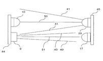
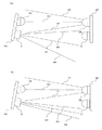
まず、図5に示すように、光送信機1の第1の光送信手段9と第2の光受信手段10とが一枚の基板44上に設置され、送信軸及び受信軸が平行に保たれている。さらに、光受信機16の第1の光受信手段17と第2の光送信手段29とが基板45上に設置され、送信軸及び受信軸が平行に保たれている。光送信機1及び光受信機16の光学素子の送受信軸が平行に確保されている場合には、光送信機1の第2の光受信手段10における受光軸50を光受信機16の第2の光送信手段29へ向ける(すなわち、4分割PDの各PDの受光レベルが一致するようにする)ことで、結果的に光送信機1の第1の光送信手段9から放出される第1の光送信信号40は、光受信機16の第1の光受信手段17へ当てることが可能となり、第1の光受信手段17によって第1の光送信信号40を受信することが可能となる。すなわち、この状態は、光送信機1と光受信機16との光軸が合っている状態である。
First, as shown in FIG. 5, the first optical transmission means 9 and the second optical reception means 10 of the optical transmitter 1 are installed on a
しかしながら、上述したように、図5のような各光学素子の受発光軸を正確に平行にすることは非常に困難で、各素子自体の軸ずれのばらつきや組立時の組立誤差などによって軸の平行を確保することが量産工程において大きな負担となる。そこで、一般に各軸の平行が確保されない場合について図6を用いて説明する。図6は、第2の光受信手段10の受光軸50及び第1の光送信手段9の発光軸51が基板44への素子取り付け時に平行が確保できていない場合であって、第2の光受信手段10の受光軸50を光受信機16の第2の光送信手段29へ合わせた場合における光送信機1と光受信機16との間の光軸のずれの様子を示している。なお、図6の(a)には、第1の光送信信号40が比較的広い指向角で放出される場合が示されており、図6の(b)には、第1の光送信信号40が狭い指向角で放出される場合が示されている。
However, as described above, it is very difficult to make the light receiving and emitting axes of each optical element as shown in FIG. 5 exactly parallel, and the axis of the optical element varies depending on variations in the axis misalignment of each element and assembly errors during assembly. Ensuring parallelism is a major burden in the mass production process. Therefore, a case where the parallelism of each axis is not generally secured will be described with reference to FIG. FIG. 6 shows a case where the
これらからわかるように、第1の光送信手段9の発光軸51と第2の光受信手段10の受光軸50の平行が確保されていない状況では、たとえ第2の光受信手段10の受光軸50を光受信機16の第2の光送信手段29へ合わせても、光送信機1の第1の光送信手段9の発光軸51は光受信機16の第1の光受信手段17からそれてしまう。図6の(a)に示すように、第1の光送信信号40の放射指向角が比較的広い場合には各軸が多少ずれても第1の光送信信号40が第1の光受信手段17を捕らえることができるかもしれない。しかし、図6の(b)に示すように、伝送速度、伝送距離が求められる光無線伝送装置では第1の光送信信号40の放射指向角を狭くする必要があり、このような光無線伝送装置では、わずかな軸のずれにおいても第1の光送信信号40が第1の光受信手段17からそれてしまい、伝送路を確保できないことがあり大きな問題となる。
As can be seen from these, in the situation where the
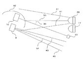
また、上述したような各光学素子の軸のずれが原因となる光送信機1及び光受信機16間での光軸のずれに加えて、実際の光無線伝送装置を考慮すると、透過光学フィルタなどの外装での光の屈折などによる軸のずれ問題なども挙げられる。これについて、図7を用いて説明する。図7では、光送信機1及び光受信機16の各光学受発光手段の間に外装などとして取り付けられた透過板42が存在する場合について説明する。光送信機1と光受信機16との間に不要な外乱光の除去などを目的とした光学フィルタなどの透過板42がある場合、光受信機16からの第2の光送信信号41は透過板42で屈折することになり、光送信機1の第2の光受信手段10は第2の光送信信号41が図7中に示した第2の光送信手段29の虚像39の位置から放たれているように認識する。これによって、光送信機1は第2の光受信手段10の受光軸50を虚像39の方向に向けることとなり、光送信機1の第1の光送信手段9から放たれる第1の光送信信号40を光受信機16の第1の光受信手段17へ当てることができず、異なる方向へ第1の光送信信号40を放つことになる。
In addition to the optical axis misalignment between the optical transmitter 1 and the
以上説明したように、光送信機1と光受信機16との光通信光軸を合わせるためには、図3、図4A及び図4Bの表を用いて説明したように一方が放つパイロット光を、他方が4分割PD素子などによって受光し、そのレベル情報に基づいて方向合わせをするだけでは正確な光軸調整が困難であり、狭い指向角の光を用いる光無線伝送装置の実現には不十分である。このため、狭い指向角の光を用いた光無線伝送装置では、図2で説明したように、光受信機16側が光送信機1からの第1の光送信信号40の受信状態の送達情報を折り返し返信することで、光送信機1は最終的にこの光受信機16からの送達情報を基に光受信機16との光軸を一致させる仕組みを有している。
As described above, in order to align the optical communication optical axes of the optical transmitter 1 and the
すなわち、光送信機1は、光受信機16へ通信光軸を合わせるために、まずパイロット光の受信レベルの情報に基づいて、素早く第2の光受信手段10及び/又は第1の光送信手段9を光受信機16の方向へ向け、その後、光受信機16から第1の光送信信号40の受信状況を知らせる送達情報に基づいて、光受信機16の第1の光受信手段17が第1の光送信信号40を正しく受信できるようになるまで光受信機16との間の通信光軸を調整する。
In other words, in order to align the communication optical axis with the
ここで、光送信機1が光受信機16との間の通信光軸を最終的に合わせるためには、光受信機16からの受信状況(送達情報)を基にした光軸調整が必要であるが、このような光軸調整(以下、送達確認光軸調整とも言う)では光受信機16の方向を知ることはできず、速やかに通信光軸のずれの調整を実現することは難しく、ある程度の時間をかけなければならない。ここで、送達情報は上述した受信エラーレート情報を含むものである。また、送達確認光軸調整では、上述したように光受信機16の方向が不明であるため、場合によっては正しい方向とは逆の方向へ調整してしまうようなケースも生じ、それを踏まえて最終的な光軸が一致する位置を見つけ出すことになる。もちろん、方向調整移動アルゴリズムなどを工夫することで、ある程度スムーズな送達確認光軸調整が可能となることが予想されるが、処理が重くなり制御部5への負担や処理速度に起因して結果として高速な調整が期待できないことも考えられる。
Here, in order for the optical transmitter 1 to finally align the communication optical axis with the
また、図2のような光無線伝送装置では、使用中に光送信機1がわずかにずれてしまったりして映像の一部が乱れるようなことが起こり得る。このような場合に、送達確認光軸調整で送信光軸を再調整すると、最初の調整である初動作において、必ずしも映像の乱れが回復できる方向へ調整されるとは限らず、場合によってはいったん映像が一層乱れる方向に動いてしまうこともあり、ユーザにとっては使用上不快なものとなってしまう。 Further, in the optical wireless transmission apparatus as shown in FIG. 2, it is possible that the optical transmitter 1 is slightly shifted during use and a part of the image is disturbed. In such a case, if the transmission optical axis is readjusted by the delivery confirmation optical axis adjustment, the initial operation, which is the first adjustment, is not necessarily adjusted in a direction in which the disturbance of the image can be recovered. The image may move in a more disturbing direction, which is uncomfortable for the user.
そこで、本発明では、いったん送達確認光軸調整を用いて光送信機1と光受信機16との間の送信光軸を合わせた後に衝撃や信号などによって光送信機1がずれて光軸がずれた場合には、送達確認光軸調整で光軸を再調整するのではなく、第2の光送信信号41の受光レベルによって方向判断する光軸調整を行うことにより、比較的速やかに光軸を調整し、伝送路を回復するものである。これによって、ユーザは上述したような使用時に光軸の再調整が発生しても不快感がなく光軸の復旧を待つことができる。
Therefore, in the present invention, after the transmission optical axis between the optical transmitter 1 and the
ただし、上述したように、光送信機1と光受信機16との間の送信光軸の再調整時における第2の光送信信号41の受光レベルの情報による方向合わせでは、図6及び図7で説明したように各光学素子の送受信軸の組み立て時のずれや外装での光の屈折の影響などがあるため、必ずしも第2の光受信手段10の各受光素子における第2の光送信信号41の受光レベルの一致するところが光軸の一致する位置とは限らない。そこで、本発明では、いったん送達確認光軸調整によって光軸が合ったならば、あらかじめ光送信機1に記憶された第1補正係数を用いてパイロット光の受光レベルを補正し、迅速、かつ正確に光軸を合わせることを可能とする。ここで、第1補正係数とは、例えば光軸がずれた後、光軸がおおよそ合うように光軸のずれた後に受信する受光レベルに乗算するための、初期時に設定される係数を言うがこれに限られるものではない。
However, as described above, in the direction alignment based on the light reception level information of the second
図8には、本発明の第1の実施の形態に係る光送信機1の構成の一部が示されている。図8に示すように、制御部5は、第2の光送信信号であるパイロット光41の第2の光受信手段10における各PD素子での受光レベルを基に、第2の光受信手段10及び/又は第1の光送信手段9の方向調整をし、光受信機16からの受信状況(送達情報)に基づいて通信光軸を正確に合わせた後、使用中に何らかの原因で通信光軸がずれた場合に、第1補正係数により第2の光受信手段10の各PD素子の受光レベルを補正する。
FIG. 8 shows a part of the configuration of the optical transmitter 1 according to the first embodiment of the present invention. As shown in FIG. 8, the
また、制御部5は第2の光受信手段10及び第1の光送信手段9の方向を駆動制御するための光軸調整制御部35を有している。光軸調整制御部35は、第2の光受信手段10及び/又は第1の光送信手段9の方向を変えるごとに、第2の光受信手段10の各受光素子で受信される信号を順次選択させるために信号セレクト回路12を制御し、第1補正係数記録メモリ37から第1補正係数を読出し、レベル補正演算部36へ引き渡す。レベル補正演算部36は、受信レベル検出回路15から送られる各受光素子(PD1、PD2、PD3、PD4)の受光レベルを第1補正係数記録メモリ37から得た第1補正係数で乗じ(演算し)て、光軸調整制御部35へ送る。
In addition, the
光軸調整制御部35は、レベル補正演算部36から送られる補正処理された各受光素子(PD1、PD2、PD3、PD4)の受光レベルを比較し、それに応じて駆動手段7、8を制御して第2の光受信手段10及び/又は第1の光送信手段9の向いている方向を変える。このような動作を第2の光受信手段10の各受光素子の補正後の受光レベルが一致するまで繰り返すことにより光送信機1の光軸を光受信機16へ合わせる。
The optical axis
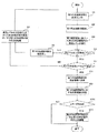
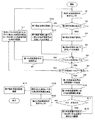
次に、本発明の第1の実施の形態に係る光送信機における光軸調整の動作フローについて図9を用いて説明する。まず、制御部5が信号セレクト回路12を制御して第2の光送信信号(パイロット光)41を順次セレクトする(ステップS1)。制御部5は、第1補正係数記録メモリ37から第1補正係数を読み出す(ステップS2)。制御部5のレベル補正演算部36は、受信レベル検出回路15から送られる第2の光送信信号41の受光レベルに読み出された第1補正係数を乗じて(演算して)、受光レベルを補正する(ステップS3)。制御部5は、補正された受光レベルが一定のレベル以上の受光レベルであるか否かを判定する(ステップS4)。これは、第2の光受信手段10の指向角内に光受信機16があるかを判定することで、外乱光などのノイズ受信による誤判定を避けるためのものである。この判定で一定のレベルを超えた受信が無い場合に、制御部5は第1の光送信手段9の発光を停止させ(ステップS5)、不必要な第1の光送信信号40の放出を避け、周辺外界への配慮をする。制御部5の光軸調整制御部35は、駆動制御部6を制御して駆動手段7、8を駆動させ、第2の光受信手段10及び/又は第1の光送信手段9の方向を駆動する(ステップS6)。
Next, an operation flow of optical axis adjustment in the optical transmitter according to the first embodiment of the present invention will be described with reference to FIG. First, the
また、ステップS4において、一定レベル以上の受光レベルであると判定された場合に、制御部5はすべての受光レベルが一致しているか否かを判定する(ステップS7)。一致していないと判定された場合には、上述したステップS6の処理が行われる。受光レベルがすべて一致していると判定された場合には、第1の光送信手段9は、第1の光送信信号40を光受信機16へ送信し(ステップS8)、第2の光受信手段10は、第1の光送信信号40に対する送達情報を光受信機16から受信する(ステップS9)。制御部5は、受信した送達情報にエラーがあるか否かを判定し(ステップS10)、エラーが無いと判定された場合には光軸は合ったということで終了する。一方、ステップS10においてエラーがあると判定された場合に、制御部5の光軸調整制御部35は、エラーの無い位置を探すために第2の光受信手段10及び/又は第1の光送信手段9を方向駆動させる(ステップS11)。なお、上述した実施の形態は一例であり、その構成は適宜変更可能である。
Further, when it is determined in step S4 that the light reception level is equal to or higher than a certain level, the
<第2の実施の形態>
次に、本発明の第2の実施の形態に係る光送信機について図10及び図11を用いて説明する。本発明の第2の実施の形態に係る光送信機1も上述した本発明の第1の実施の形態に係る光送信機1とほぼ同様の構成及び機能であるため、重複する部分については説明を省略し、相違する部分について説明する。構成上の相違部分は、第2補正係数を記憶する第2補正係数記録メモリ38を有するところである。まず、本発明の第2の実施の形態に係る光送信機1の構成の一部について図10を用いて説明する。図10に示すように、制御部5は、第2の光送信信号(パイロット光)41の第2の光受信手段10における各PD素子での受光レベルを基に、第2の光受信手段10及び/又は第1の光送信手段9の方向調整をし、光受信機16からの受信状況(送達情報)に基づいて通信光軸を正確に合わせた後、通信光軸が正確に合っている状態での第2の光受信手段10の各PD素子の受信レベルから算出した第2補正係数を第2補正係数記録メモリ38に記憶し、使用中に何らかの原因で通信光軸がずれた場合に、第2補正係数記録メモリ38に記憶された第2補正係数により第2の光受信手段10の各PD素子の受光レベルを補正する。ここで、第2補正係数とは、例えば通信光軸が正確に合っている状態における第2の光受信手段10の各PD素子の受信レベルを等しくするような係数を言うがこれに限られるものではない。
<Second Embodiment>
Next, an optical transmitter according to a second embodiment of the present invention will be described with reference to FIGS. Since the optical transmitter 1 according to the second embodiment of the present invention has almost the same configuration and function as those of the above-described optical transmitter 1 according to the first embodiment of the present invention, overlapping portions will be described. Will be omitted, and different parts will be described. The difference in configuration is that it has a second correction
また、制御部5は第2の光受信手段10及び第1の光送信手段9の方向を駆動制御するための光軸調整制御部35を有している。光軸調整制御部35は、第2の光受信手段10及び第1の光送信手段9の方向を変えるごとに、第2の光受信手段10の各受光素子で受信される信号を順次選択させるために信号セレクト回路12を制御し、第1補正係数記録メモリ37又は第2補正係数記録メモリ38から各補正係数を読出し、レベル補正演算部36へ引き渡す。ここで、光軸調整制御部35は、第2補正係数記録メモリ38に第2補正係数があれば第2補正係数をレベル補正演算部36へ引き渡し、なければ第1補正係数をレベル補正演算部36へ引き渡す。レベル補正演算部36は、受信レベル検出回路15から送られる各受光素子(PD1、PD2、PD3、PD4)の受光レベルを第1補正係数記録メモリ37又は第2補正係数記録メモリ38から得た各補正係数で乗じ(演算し)て、光軸調整制御部35へ送る。
In addition, the
光軸調整制御部35は、レベル補正演算部36から送られる補正処理された各受光素子(PD1、PD2、PD3、PD4)の受光レベルを比較し、それに応じて駆動手段7、8を制御して第2の光受信手段10及び/又は第1の光送信手段9の向いている方向を変える。このような動作を第2の光受信手段10の各受光素子の補正後の受光レベルが一致するまで繰り返すことにより光送信機1の光軸を光受信機16へ合わせる。
The optical axis
次に、本発明の第2の実施の形態に係る光送信機における光軸調整の動作フローについて図11を用いて説明する。まず、制御部5が信号セレクト回路12を制御して第2の光送信信号(パイロット光)41を順次セレクトする(ステップS1)。制御部5は、第2補正係数記録メモリ38に第2補正係数があるか否かを判定し(ステップS2)、第2補正係数があると判定した場合に第2補正係数記録メモリ38から第2補正係数を読み出す(ステップS3)。制御部5のレベル補正演算部36は、第2補正係数を用いて受光レベルを補正する(ステップS4)。次に、制御部5は、補正された受光レベルが一定のレベル以上の受光レベルであるか否かを判定する(ステップS5)。これは、第2の光受信手段10の指向角内に光受信機16があるか否かを判定することで、外乱光などのノイズ受信による誤判定を避けるためのものである。この判定で一定のレベルを超えた受信が無い場合に、制御部5は第1の光送信手段9の送信を停止させ(ステップS6)、不必要な第1の光送信信号40の放出を避け、周辺外界への配慮をする。制御部5の光軸調整制御部35は、駆動制御部6を制御して駆動手段7、8を駆動させ、第2の光受信手段10及び/又は第1の光送信手段9の向きを駆動する(ステップS7)。
Next, an operation flow of optical axis adjustment in the optical transmitter according to the second embodiment of the present invention will be described with reference to FIG. First, the
また、ステップS5において、一定レベル以上の受光レベルであると判定された場合に、制御部5はすべての受光レベルが一致しているか否かを判定する(ステップS8)。一致していないと判定された場合には、上述したステップS7の処理が行われる。受光レベルがすべて一致していると判定された場合には、第1の光送信手段9は、第1の光送信信号40を光受信機16へ送信し(ステップS9)、第2の光受信手段10は、第1の光送信信号40に対する送達情報を光受信機16から受信する(ステップS10)。制御部5は、受信した送達情報にエラーがあるか否かを判定し(ステップS11)、エラーが無いと判定された場合に、制御部5が信号セレクト回路12を制御して第2の光送信信号(パイロット光)41を順次セレクトする(ステップS12)。
If it is determined in step S5 that the received light level is equal to or higher than a certain level, the
制御部5は、選択した受光レベルをすべて等しくするような係数である第2補正係数を算出し(ステップS13)、第2補正係数を登録、更新する(ステップS14)。一方、ステップS11においてエラーがあると判定された場合に、制御部5の光軸調整制御部35は、エラーの無い位置を探すために第2の光受信手段10及び/又は第1の光送信手段9を方向駆動させる(ステップS15)。なお、上述した実施の形態は一例であり、その構成は適宜変更可能である。なお、ステップS2において第2補正係数がないと判定した場合に第1補正係数記録メモリ37から第1補正係数を読み出し(ステップS16)、制御部5のレベル補正演算部36は、受信レベル検出回路15から送られる第2の光送信信号41の受光レベルに読み出された第1補正係数を乗じて(演算して)、受光レベルを補正する(ステップS17)。そして、ステップS5以降に続く。
The
なお、ステップS12の後に、制御部5のレベル補正演算部36は、受信レベル検出回路15から送られる第2の光送信信号41の受光レベルに第1補正係数記録メモリ37から読み出された第1補正係数を乗じて(演算して)、受光レベルを補正してからステップS13以降を行ってもよい。
Note that after
本発明に係る光送信機は、狭い指向角の送信光を使用するような光無線伝送装置でも簡単に光軸合わせをすることが可能であり、使用中の光軸のずれにおいても速やかに再調整することができるため、光無線伝送装置を構成する光送信機と光受信機との間の光軸を合わせる光送信機などに有用である。 The optical transmitter according to the present invention can easily align the optical axis even in an optical wireless transmission apparatus that uses transmission light with a narrow directivity angle. Since it can be adjusted, it is useful for an optical transmitter that aligns the optical axis between an optical transmitter and an optical receiver constituting the optical wireless transmission apparatus.
1 光送信機
2 符号化回路
3、19 二値化回路
4、28 発光素子ドライバ
5 制御部(判断手段、調整手段、算出手段)
6 駆動制御部
7、8、23 駆動手段
9 第1の光送信手段(送信手段)
10 第2の光受信手段(受信手段)
11、18 受光回路
12 信号セレクト回路
13 復調回路
14 パケット検出・解析手段
15 受信レベル検出回路
16 光受信機
17 第1の光受信手段
20 信号レベル検出回路
21 シンボル復号回路
22 水平可動部
23 垂直可動部
24 シンボルエラー検出回路
25 エラーレート算出回路
26 エラーレートパケット生成回路
27 変調回路
29 第2の光送信手段
30 屈折角
35 光軸調整制御部
36 レベル補正演算部
37 第1補正係数記録メモリ(記憶手段、第1の記憶手段)
38 第2補正係数記録メモリ(第2の記憶手段)
39 虚像
40 第1の光送信信号(送信光)
41 第2の光送信信号(パイロット光)
42 透過板(光学フィルタ)
44、45 基板
50 第2の光受信手段の受光軸
51 第1の光送信手段の発光軸
52 第2の光送信手段の発光軸
53 映像制御装置
54 映像表示装置
300 光源
PD1、PD2、PD3、PD4 受光素子
DESCRIPTION OF SYMBOLS 1
6 Drive
10 Second optical receiving means (receiving means)
DESCRIPTION OF
38 Second correction coefficient recording memory (second storage means)
39
41 Second optical transmission signal (pilot light)
42 Transmission plate (optical filter)
44, 45
Claims (2)
複数の受信素子によって構成され、前記光軸を調整するための第2の光信号を前記光受信機から受信する受信手段と、
前記第2の光信号の光軸のずれを補正する際の基準となる補正係数を記憶する記憶手段と、
前記受信手段の各前記受信素子によって受信された前記第2の光信号の受信レベルが所定の条件を満たしているか否かを判断する判断手段と、
前記判断手段によって前記所定の条件を満たさないと判断された場合に、前記所定の条件を満たすように前記受信手段及び/又は前記送信手段の向きを調整し、また前記判断手段によって前記所定の条件を満たすと判断された場合であって、前記受信手段によって受信された前記第2の光信号に前記送信手段が送信した前記第1の光信号に対する受信エラーを示す受信エラーレート情報が含まれている場合に、前記受信エラーが無くなるように前記受信手段及び/又は前記送信手段の向きを調整し、光軸を合わせる調整手段とを備え、
前記調整手段は、光軸が合わせられた後に前記光軸のずれが生じた際、前記記憶手段に記憶された前記補正係数、及び前記光軸のずれが生じた後に前記受信手段によって受信される前記第2の光信号の受信レベルに基づいて、前記受信手段及び/又は前記送信手段の向きを調整し、光軸を合わせることを特徴とする光送信機。 In the optical transmitter for adjusting the optical axis of the first optical signal to be optically transmitted from the transmission means to the optical receiver,
Receiving means configured by a plurality of receiving elements and receiving a second optical signal for adjusting the optical axis from the optical receiver;
Storage means for storing a correction coefficient serving as a reference when correcting a deviation of the optical axis of the second optical signal;
Determining means for determining whether or not the reception level of the second optical signal received by each receiving element of the receiving means satisfies a predetermined condition;
When the determination means determines that the predetermined condition is not satisfied, the direction of the receiving means and / or the transmission means is adjusted so as to satisfy the predetermined condition, and the predetermined condition is determined by the determination means. The second optical signal received by the receiving means includes reception error rate information indicating a reception error for the first optical signal transmitted by the transmitting means. Adjusting the direction of the receiving means and / or the transmitting means so that the reception error is eliminated, and an adjusting means for adjusting the optical axis,
When the optical axis shift occurs after the optical axes are aligned, the adjustment unit is received by the receiving unit after the correction coefficient stored in the storage unit and the optical axis shift have occurred. An optical transmitter characterized in that, based on the reception level of the second optical signal, the direction of the receiving means and / or the transmitting means is adjusted to align the optical axis.
複数の受信素子によって構成され、前記光軸を調整するための第2の光信号を前記光受信機から受信する受信手段と、
前記第2の光信号の光軸のずれを補正する際の基準となる第1の補正係数を記憶する第1の記憶手段と、
前記受信手段の各前記受信素子によって受信された前記第2の光信号の受信レベルが所定の条件を満たしているか否かを判断する判断手段と、
前記判断手段によって前記所定の条件を満たさないと判断された場合に、前記所定の条件を満たすように前記送信手段及び/又は前記受信手段の向きを調整し、また前記判断手段によって前記所定の条件を満たすと判断された場合であって、前記受信手段によって受信された前記第2の光信号に前記送信手段が送信した前記第1の光信号に対する受信エラーを示す受信エラーレート情報が含まれている場合に、前記受信エラーが無くなるように前記送信手段及び/又は前記受信手段の向きを調整し、光軸を合わせる調整手段と、
前記調整手段によって光軸が合わせられた際の前記第2の光信号の受信レベルの情報に基づいて、前記光軸のずれを補正する際の基準となる第2の補正係数を算出する算出手段と、
前記算出手段によって算出された前記第2の補正係数を記憶する第2の記憶手段とを備え、
前記調整手段は、光軸が合わせられた後に前記光軸のずれが生じた際、前記第2の記憶手段に前記第2の補正係数が記憶されている場合には、前記光軸のずれが生じた後に前記受信手段によって受信される前記第2の光信号の受信レベル及び前記第2の補正係数に基づいて前記第2の光信号の受信レベルを補正し、前記第2の記憶手段に前記第2の補正係数が記憶されていない場合には、前記受信手段によって受信される前記第2の光信号の受信レベル及び前記第1の記憶手段に記憶された前記第1の補正係数に基づいて前記第2の光信号の受信レベルを補正し、
前記判断手段は、補正された前記第2の光信号の受信レベルが前記所定の条件を満たしているか否かを判断し、
前記調整手段は、前記判断手段によって前記所定の条件を満たすと判断された場合、前記受信手段によって受信される前記第2の光信号に、前記所定の条件を満たすと判断された後に前記送信手段が送信した前記第1の光信号に対する受信エラーを示す受信エラーレート情報が含まれている場合に、前記受信エラーが無くなるように前記送信手段及び/又は前記受信手段の向きを調整し、光軸を合わせることを特徴とする光送信機。
In the optical transmitter for adjusting the optical axis of the first optical signal to be optically transmitted from the transmission means to the optical receiver,
Receiving means configured by a plurality of receiving elements and receiving a second optical signal for adjusting the optical axis from the optical receiver;
First storage means for storing a first correction coefficient serving as a reference when correcting a deviation of the optical axis of the second optical signal;
Determining means for determining whether or not the reception level of the second optical signal received by each receiving element of the receiving means satisfies a predetermined condition;
When the determination means determines that the predetermined condition is not satisfied, the direction of the transmission means and / or the reception means is adjusted so as to satisfy the predetermined condition, and the predetermined condition is determined by the determination means. The second optical signal received by the receiving means includes reception error rate information indicating a reception error for the first optical signal transmitted by the transmitting means. Adjusting means for adjusting the direction of the transmitting means and / or the receiving means so as to eliminate the reception error, and aligning the optical axis;
Calculation means for calculating a second correction coefficient serving as a reference for correcting the deviation of the optical axis based on information on the reception level of the second optical signal when the optical axis is adjusted by the adjusting means. When,
Second storage means for storing the second correction coefficient calculated by the calculation means;
When the optical axis shift occurs after the optical axes are aligned, the adjusting means may cause the optical axis shift if the second correction coefficient is stored in the second storage means. Correcting the reception level of the second optical signal based on the reception level of the second optical signal received by the receiving means and the second correction coefficient after the occurrence, and storing the second optical signal in the second storage means; If the second correction coefficient is not stored, based on the reception level of the second optical signal received by the receiving means and the first correction coefficient stored in the first storage means. Correcting the reception level of the second optical signal;
The determination means determines whether the corrected reception level of the second optical signal satisfies the predetermined condition,
When the determination unit determines that the predetermined condition is satisfied by the determination unit, the adjustment unit determines that the second optical signal received by the reception unit satisfies the predetermined condition and then transmits the transmission unit. If the reception error rate information indicating a reception error with respect to the first optical signal transmitted by the receiver is included, the direction of the transmission unit and / or the reception unit is adjusted so that the reception error is eliminated, and the optical axis An optical transmitter characterized by combining.
Priority Applications (1)
| Application Number | Priority Date | Filing Date | Title |
|---|---|---|---|
| JP2004102533A JP2005294899A (en) | 2004-03-31 | 2004-03-31 | Optical transmitter |
Applications Claiming Priority (1)
| Application Number | Priority Date | Filing Date | Title |
|---|---|---|---|
| JP2004102533A JP2005294899A (en) | 2004-03-31 | 2004-03-31 | Optical transmitter |
Publications (1)
| Publication Number | Publication Date |
|---|---|
| JP2005294899A true JP2005294899A (en) | 2005-10-20 |
Family
ID=35327401
Family Applications (1)
| Application Number | Title | Priority Date | Filing Date |
|---|---|---|---|
| JP2004102533A Pending JP2005294899A (en) | 2004-03-31 | 2004-03-31 | Optical transmitter |
Country Status (1)
| Country | Link |
|---|---|
| JP (1) | JP2005294899A (en) |
Cited By (2)
| Publication number | Priority date | Publication date | Assignee | Title |
|---|---|---|---|---|
| KR100804739B1 (en) * | 2005-12-08 | 2008-02-20 | 한국광기술원 | Performance testing apparatus for free space optics system |
| JP2010510481A (en) * | 2006-11-21 | 2010-04-02 | エフ.ホフマン−ラ ロシュ アーゲー | Means and methods for optimization of diagnostic and therapeutic approaches in chronic arterial disease based on detection of troponin T and NT-proBNP |
-
2004
- 2004-03-31 JP JP2004102533A patent/JP2005294899A/en active Pending
Cited By (2)
| Publication number | Priority date | Publication date | Assignee | Title |
|---|---|---|---|---|
| KR100804739B1 (en) * | 2005-12-08 | 2008-02-20 | 한국광기술원 | Performance testing apparatus for free space optics system |
| JP2010510481A (en) * | 2006-11-21 | 2010-04-02 | エフ.ホフマン−ラ ロシュ アーゲー | Means and methods for optimization of diagnostic and therapeutic approaches in chronic arterial disease based on detection of troponin T and NT-proBNP |
Similar Documents
| Publication | Publication Date | Title |
|---|---|---|
| US20130082162A1 (en) | Method of Directing an Optical Receiver Toward a Light Source and an Apparatus of Practising the Method | |
| US20070217795A1 (en) | Improvements Relating to Reception in Optical Networks | |
| US20110150493A1 (en) | Optical module | |
| WO2002073835A1 (en) | Transceiver for free-space optical communication system | |
| JP2005294899A (en) | Optical transmitter | |
| JP2005175842A (en) | Photodetector and optical space transmission apparatus | |
| JP2007036940A (en) | Optical radio transmitter, light-transmitting unit and light-receiving unit | |
| JP2006238139A (en) | Spatial optical transmission system and mobile terminal | |
| US7379674B2 (en) | Optical transmission device | |
| JP4513057B2 (en) | Optical transmission system, optical wireless transmitter, and optical transmission method | |
| JP4379160B2 (en) | Optical wireless transmission device | |
| JP2009520249A (en) | Scanning engine with guide light | |
| JP2007074105A (en) | Photodetector | |
| JP2007282144A (en) | Optical space communication apparatus | |
| JP4379161B2 (en) | Optical transmitter | |
| JP2006340075A (en) | Hybrid optical axis correcting device of optical spatial communication system | |
| JP2006042205A (en) | Optical radio transmission device | |
| JP3870198B2 (en) | Optical space transmission equipment | |
| JP2005026929A (en) | Optical radio transmitter | |
| JP2015065492A (en) | Optical space communication system | |
| JP2005229359A (en) | Optical space communication apparatus | |
| JP2002111590A (en) | Receiver by optical signal transmission | |
| KR102424666B1 (en) | Lidar system with error correction function and error correction method therof | |
| JP2003224529A (en) | Optical spatial communication apparatus | |
| JP2006197078A (en) | Optical space communication system |
Legal Events
| Date | Code | Title | Description |
|---|---|---|---|
| A621 | Written request for application examination |
Free format text: JAPANESE INTERMEDIATE CODE: A621 Effective date: 20060630 |
|
| A977 | Report on retrieval |
Free format text: JAPANESE INTERMEDIATE CODE: A971007 Effective date: 20080623 |
|
| A131 | Notification of reasons for refusal |
Free format text: JAPANESE INTERMEDIATE CODE: A131 Effective date: 20080627 |
|
| A02 | Decision of refusal |
Free format text: JAPANESE INTERMEDIATE CODE: A02 Effective date: 20081024 |