JP2005294898A - Viterbi decoding method, decoding apparatus, mobile station radio apparatus, base station radio apparatus, and mobile communication system - Google Patents
Viterbi decoding method, decoding apparatus, mobile station radio apparatus, base station radio apparatus, and mobile communication system Download PDFInfo
- Publication number
- JP2005294898A JP2005294898A JP2004102520A JP2004102520A JP2005294898A JP 2005294898 A JP2005294898 A JP 2005294898A JP 2004102520 A JP2004102520 A JP 2004102520A JP 2004102520 A JP2004102520 A JP 2004102520A JP 2005294898 A JP2005294898 A JP 2005294898A
- Authority
- JP
- Japan
- Prior art keywords
- state
- path
- traceback
- time
- bit string
- Prior art date
- Legal status (The legal status is an assumption and is not a legal conclusion. Google has not performed a legal analysis and makes no representation as to the accuracy of the status listed.)
- Pending
Links
Images


Landscapes
- Detection And Correction Of Errors (AREA)
- Error Detection And Correction (AREA)
- Detection And Prevention Of Errors In Transmission (AREA)
Abstract
【課題】 少ないトレースバック回数で正しい復号ビット列を得ることが可能なビタビ復号方法、復号化装置、移動局無線装置、基地局無線装置および移動通信システムを提供すること。
【解決手段】 誤り訂正復号化装置102に開始状態メモリ110を設け、ACS演算中の全時点の全状態の生き残りパスについて、そのパスの尤度であるパスメトリックを記憶すると同時に、その生き残りパスのACS演算開始時点(時点S)の開始状態を、開始状態メモリ110に記憶し、ACS処理終了後、トレースバック制御回路113は、(ACS演算終了時点(時点E)の状態)=(ACS演算開始時点の開始状態)を満たす状態からのみトレースバックを行うことで、無駄なトレースバック処理を回避する。
【選択図】 図1PROBLEM TO BE SOLVED: To provide a Viterbi decoding method, a decoding device, a mobile station radio device, a base station radio device and a mobile communication system capable of obtaining a correct decoded bit string with a small number of tracebacks.
A start state memory 110 is provided in an error correction decoding apparatus 102, and for all surviving paths at all times during ACS calculation, a path metric that is the likelihood of the path is stored, and at the same time, the surviving path The start state of the ACS calculation start time (time S) is stored in the start state memory 110, and after the ACS processing is finished, the traceback control circuit 113 sets (ACS calculation end time (time E) state) = (ACS calculation start) By performing the trace back only from the state satisfying the start state at the time), unnecessary trace back processing is avoided.
[Selection] Figure 1
Description
本発明は、デジタル携帯電話等の分野に使用される、巡回畳み込み符号についてのビタビ復号方法、復号化装置、移動局無線装置、基地局無線装置および移動通信システムに関する。 The present invention relates to a Viterbi decoding method, a decoding apparatus, a mobile station radio apparatus, a base station radio apparatus, and a mobile communication system for cyclic convolutional codes used in the field of digital cellular phones and the like.
ビタビ復号法は、畳み込み符号の復号方法の1つであり、特に移動通信システムでは多く採用されている方法である。 The Viterbi decoding method is one of the decoding methods for convolutional codes, and is a method that is often used particularly in mobile communication systems.
ビタビ復号法を説明する前に、まず、畳み込み符号化について、図9を参照して説明する。畳み込み符号化には、通常の畳み込み符号化(線形畳み込み符号化)と、巡回畳み込み符号化がある。 Before describing the Viterbi decoding method, first, convolutional coding will be described with reference to FIG. Convolutional coding includes normal convolutional coding (linear convolutional coding) and cyclic convolutional coding.
ここで、「巡回畳み込み符号化」は、例えば、移動通信分野における特定の制御信号の伝送に用いられている。本発明は、この「巡回畳み込み符号」の復号化技術に関する。 Here, “cyclic convolutional coding” is used, for example, for transmission of a specific control signal in the mobile communication field. The present invention relates to a decoding technique of this “cyclic convolutional code”.
ここで、「巡回畳み込み符号化」とは、初期状態と終了状態が同一の状態となるように情報ビット列Uを入力して符号語を生成する符号化をいい、巡回入力畳み込み符号化と呼ばれることもある。 Here, “cyclic convolutional coding” refers to coding in which a code word is generated by inputting an information bit string U so that an initial state and an end state are the same, and is called cyclic input convolutional coding. There is also.
以下、順を追って説明する。 In the following, description will be given in order.
図9は畳み込み符号化器の例であり、この符号化器の入力側に情報ビット列Uを入力することで、出力側に符号化率r=1/2、拘束長k=3、2個の生成多項式がそれぞれG1(X)=X2+1及びG2(X)=X2+X+1の畳み込み符号化が行われた符号化ビット列Xが得られる。 FIG. 9 shows an example of a convolutional encoder. By inputting an information bit string U to the input side of this encoder, an encoding rate r = 1/2, a constraint length k = 3, An encoded bit string X obtained by performing convolutional encoding with generator polynomials G1 (X) = X 2 +1 and G2 (X) = X 2 + X + 1, respectively, is obtained.
畳み込み符号化器には、シフトレジスタSR1とSR2が従属接続され、SR2には情報ビット列Uが順次入力され、出力側では1ビットの情報ビット入力に対し、2ビットの符号化ビット出力(X1、X2)が得られる。 Shift registers SR1 and SR2 are cascade-connected to the convolutional encoder, and an information bit string U is sequentially input to SR2. On the output side, a 2-bit encoded bit output (X1,. X2) is obtained.
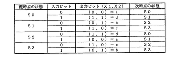
このとき、シフトレジスタSR1、及びSR2のビット内容(SR1、SR2)を状態と呼び、図9の畳み込み符号化器では次の4つ(S0〜S3)のいずれかの状態をとりうる。
S0=(0、0)
S1=(0、1)
S2=(1、0)
S3=(1、1)
At this time, the bit contents (SR1, SR2) of the shift registers SR1 and SR2 are called states, and the convolutional encoder shown in FIG. 9 can take one of the following four states (S0 to S3).
S0 = (0, 0)
S1 = (0, 1)
S2 = (1, 0)
S3 = (1, 1)
一般に、1ビット入力かつ符号化率r=1/2の畳み込み符号化器の状態数は、拘束長kを用いて2k-1状態となる。すなわち、状態数は拘束長に従って指数関数的に増大する。 In general, the number of states of a convolutional encoder with 1-bit input and coding rate r = 1/2 is 2 k−1 using the constraint length k. That is, the number of states increases exponentially according to the constraint length.
図9の符号化器の初期状態と終了状態はそれぞれ4状態考えられるが、初期状態と終了状態が同一の状態となるように情報ビット列Uを入力して符号語を生成するとき、これを「巡回畳み込み符号化」と呼ぶ。 There are four possible initial states and end states of the encoder shown in FIG. 9, but when an information bit string U is input and a code word is generated so that the initial state and the end state are the same, this is expressed as “ This is called “cyclic convolutional coding”.
例えば、情報ビット列Uがnビット(U[0]〜U[n−1])である場合、図9の符号化器の初期状態と終了状態を同一とするためには、開始時点SにおいてSR1にU[n−2]、SR2にU[n−1]を予めセットしておき、その後U[0]〜U[n−1]を順次入力していくことにより巡回畳み込み符号が得られる。 For example, when the information bit string U is n bits (U [0] to U [n-1]), in order to make the initial state and the end state of the encoder of FIG. U [n-2] and SR [2] are set in advance in U [n-2], and then U [0] to U [n-1] are sequentially input to obtain a cyclic convolutional code.
また、現時点の符号化器の状態に対して、情報ビット(“0”または“1”)を1ビット入力すると、符号化ビット出力及び次時点の符号化器の状態が一意に定まる。この畳み込み符号化器の生成規則を図10に示す。 When one bit of information bits (“0” or “1”) is input to the current encoder state, the encoded bit output and the encoder state at the next time point are uniquely determined. A generation rule of this convolutional encoder is shown in FIG.
例えば、現時点の符号化器の状態がS3で、ビット“0”が入力された場合には、符号化ビット出力は“10”であり、次時点の符号化器の状態はS2となる。 For example, when the current encoder state is S3 and bit “0” is input, the encoded bit output is “10”, and the encoder state at the next time point is S2.
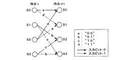
図11は図9の畳み込み符号化器の生成規則の状態遷移をトレリス図によって示したものである。図11のトレリス図において、実線のブランチは入力の情報ビットが“0”であることを示し、点線のブランチは入力の情報ビットが“1”であることを示す。さらに、ブランチ部分には符号化ビット出力(X1、X2)を示す。ただし、a=(0、0)、b=(0、1)、C=(1、0)、d=(1、1)である。 FIG. 11 is a trellis diagram showing state transitions of the generation rules of the convolutional encoder shown in FIG. In the trellis diagram of FIG. 11, a solid line branch indicates that the input information bit is “0”, and a dotted line branch indicates that the input information bit is “1”. Furthermore, the encoded bit output (X1, X2) is shown in the branch part. However, a = (0, 0), b = (0, 1), C = (1, 0), d = (1, 1).
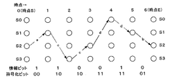
いま、例として、入力の情報ビット列Uが6ビットであり、U[0:5]=(1、1、0、0、1、0)である場合の巡回畳み込み符号化のトレリス図を図12に示す。 As an example, FIG. 12 shows a trellis diagram of cyclic convolutional coding when the input information bit string U is 6 bits and U [0: 5] = (1, 1, 0, 0, 1, 0). Shown in
図12において、横方向は符号化器への入力タイミングの時点であり(時点Sは初期時点、時点Eは終了時点)、縦方向は符号化器の状態である。このとき、符号化器の時点Sでの初期状態は(U[4]、U[5])であるからS2となっており、巡回畳み込み符号化を行っていることから、時点Eでの終了状態もS2となり、時点Sと時点Eは同一状態になる。また、図12の最下段が畳み込み符号化結果の符号化ビット列Xであり、X[0:11]=(0、0、1、0、1、0、1、1、1、1、0、1)となる。 In FIG. 12, the horizontal direction is the time of input timing to the encoder (time S is the initial time, time E is the end time), and the vertical direction is the state of the encoder. At this time, since the initial state of the encoder at time S is (U [4], U [5]), it is S2, and since cyclic convolutional coding is performed, the end at time E is completed. The state is also S2, and time S and time E are the same state. 12 is the encoded bit string X as a result of the convolutional encoding, and X [0:11] = (0, 0, 1, 0, 1, 0, 1, 1, 1, 1, 0, 1).
このように畳み込み符号化されたビット列を復号する方法のひとつにビタビ復号がある。ビタビ復号は、トレリス図上で出力されうるパタンと受信パタンとを時系列順に逐次比較し、より尤もらしいパタンを候補として残しつつ、最終的に誤りが最も少ないパタンを復号データとするアルゴリズムである。 Viterbi decoding is one of the methods for decoding the convolutionally encoded bit string. Viterbi decoding is an algorithm that sequentially compares a pattern that can be output on a trellis diagram and a received pattern in chronological order, leaves a more likely pattern as a candidate, and finally uses the pattern with the least error as decoded data. .
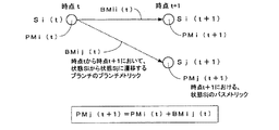
以下、巡回畳み込み符号に対する従来のビタビ復号方法を図13、図14および図15を参照しながら簡単に説明する。図13は、時点tから時点t+1にかけて状態Siが状態Siおよび状態Sjに状態遷移するときのトレリス図、図14は、従来のビタビ復号方法におけるACS処理の詳細説明図、図15は、従来のビタビ復号方法を適用するトレリス図の例である。 Hereinafter, a conventional Viterbi decoding method for a cyclic convolutional code will be briefly described with reference to FIGS. 13, 14, and 15. FIG. 13 is a trellis diagram when state Si transitions from state t to time t + 1 to state Si and state Sj, FIG. 14 is a detailed explanatory diagram of ACS processing in the conventional Viterbi decoding method, and FIG. It is an example of a trellis diagram to which the Viterbi decoding method is applied.
ビタビ復号は、ACS(Add−Compare−Select:加算−比較−選択)処理とトレースバック処理の組み合わせによって行われる。 Viterbi decoding is performed by a combination of ACS (Add-Compare-Select) processing and traceback processing.
ACS処理では、パスの尤度(確からしさ)の指標としてパスメトリックが用いられる。パスメトリックは、各時点の各状態に至るまでのパスが経由するブランチのブランチメトリックの累積加算値であり、その値が小さいほどパスが確からしいと判定する。ブランチメトリックは、ノード間の状態遷移で期待される出力ビットと受信ビットとの誤りビット数(ハミング距離:硬判定)や、信号空間上の距離(軟判定)などが用いられる。 In the ACS processing, a path metric is used as an index of path likelihood (probability). The path metric is a cumulative addition value of the branch metrics of the branches through which the path leading to each state at each time point passes, and it is determined that the path is more likely as the value is smaller. For the branch metric, the number of error bits (Hamming distance: hard decision) between the output bit and the received bit expected in the state transition between nodes, the distance in the signal space (soft decision), and the like are used.
まず、ACS処理の説明の前に、以下の説明で用いる記号について図13を用いて定義する。図13は、時点tから時点t+1にかけて状態Siが状態Si及び状態Sjに状態遷移するときのトレリス図を示したものである。いま、時点tにおける状態Siを状態Si(t)と記述する。図13中の記号PMはパスメトリックであり、PMi(t)は、状態Si(t)における生き残りパスのパスメトリックである。また、図13中の記号BMはブランチメトリックであり、BMij(t)は、状態Si(t)が状態Sj(t+1)に状態遷移するときのブランチメトリックである。 First, before describing the ACS processing, symbols used in the following description are defined with reference to FIG. FIG. 13 shows a trellis diagram when the state Si transitions to the state Si and the state Sj from the time point t to the time point t + 1. Now, state Si at time t is described as state Si (t). Symbol PM in FIG. 13 is a path metric, and PMi (t) is a path metric of a surviving path in the state Si (t). Further, symbol BM in FIG. 13 is a branch metric, and BMij (t) is a branch metric when the state Si (t) changes to the state Sj (t + 1).
なお、パスメトリックとブランチメトリックには、PMj(t+1)=PMi(t)+BMij(t)なる関係が成り立つ。 Note that a relationship of PMj (t + 1) = PMi (t) + BMij (t) is established between the path metric and the branch metric.
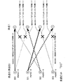
次に、ACS処理について、図14及び図15を用いて説明する。図14及び図15の各ノード内の数値は各時点各状態におけるパスメトリックである。 Next, ACS processing will be described with reference to FIGS. The numerical value in each node in FIG. 14 and FIG. 15 is a path metric in each state at each time point.
ここでは、受信データは巡回畳み込み符号化されており、且つ符号化器の初期状態は不明であることを前捏とし、ブランチメトリックにはハミング距離を用いて説明する。また、受信ビット列Yは、Y[0:11]=(0、0、1、0、1、1、1、1、1、0、0、1)とする。 Here, it is assumed that the received data is cyclic convolutionally encoded and the initial state of the encoder is unknown, and the branch metric will be described using the Hamming distance. The received bit string Y is Y [0:11] = (0, 0, 1, 0, 1, 1, 1, 1, 1, 0, 0, 1).
まず、時点0(=時点S)から時点1にかけて行われるACS処理について、図14を用いて説明する。時点0では、符号化器の初期状態が不明であるので、各状態のパスメトリック(尤度)は全て同一であり、PM0(0)=PM1(0)=PM2(0)=PM3(0)=0である。
First, ACS processing performed from time 0 (= time S) to
はじめに、状態S0(1)におけるパスメトリックPM0(1)を算出する。状態S0(1)に遷移してくるパスは、状態S0(0)及び状態S2(0)からのパスである。 First, the path metric PM0 (1) in the state S0 (1) is calculated. The path transitioning to the state S0 (1) is a path from the state S0 (0) and the state S2 (0).
状態S0(0)からのブランチメトリックは、符号化器からの期待出力が“00”であるのに対し、受信ビットがY[0:1]=“00”であるから、ハミング距離を用いて、BM00(0)=0となり、1つ目の仮のパスメトリックPMaは、PMa=PM0(0)+BM00(0)=0+0=0と記憶される。 The branch metric from state S0 (0) uses the Hamming distance because the expected output from the encoder is “00” while the received bit is Y [0: 1] = “00”. , BM00 (0) = 0, and the first temporary path metric PMa is stored as PMa = PM0 (0) + BM00 (0) = 0 + 0 = 0.
一方、状態S2(0)からのブランチメトリックは、符号化器からの期待出力が“11”であるのに対し、受信ビットが“00”であるから、ハミング距離を用いて、Bm20(0)=2となり、2つ目の仮のパスメトリックPMbは、PMb=PM2(0)+BM20(0)=0+2=2と記憶される。以上がACS処理の加算(Add)である。 On the other hand, the branch metric from state S2 (0) is Bm20 (0) using the Hamming distance because the expected output from the encoder is “11” while the received bit is “00”. = 2 and the second temporary path metric PMb is stored as PMb = PM2 (0) + BM20 (0) = 0 + 2 = 2. The above is the addition (Add) of the ACS processing.
次に、2つの仮のパスメトリックの大きさを比較(Compare)する。PMa及びPMbを比較すると、PMaの方が小さいため、状態S0(0)からのパスの尤度は状態S2(0)からのパスの尤度より大きいため、状態S0(1)では、状態S0(0)からのパスを選択(Select)し、PM0(1)=PMa=0となる。このとき、選択されたパスを生き残りパスと呼び、パス選択情報は各時点各状態の全てにおいて記憶しておく。図14において×印が打たれたパスは破棄されたパスである。 Next, the magnitudes of the two temporary path metrics are compared. When PMa and PMb are compared, since PMa is smaller, the likelihood of the path from state S0 (0) is larger than the likelihood of the path from state S2 (0). Therefore, in state S0 (1), state S0 The path from (0) is selected (Select), and PM0 (1) = PMa = 0. At this time, the selected path is called a surviving path, and the path selection information is stored in all states at each time point. In FIG. 14, a path marked with a cross is a discarded path.
次に、状態S1(1)におけるパスメトリックPM1(1)を算出する。上記と同様に考えることで、状態S0(0)から至るパスのパスメトリックPMa、及び状態S2(0)から至るパスのパスメトリックPMbはそれぞれ、
PMa=PM0(0)+BM01(0)=0+2=2(符号化器の期待出力“11”)
PMb=PM2(0)+BM21(0)=0+0=0(符号化器の期待出力“00”)
となり、PMbの方が小さいため、生き残りパスはS2(0)からのパスとなり、PM1(1)=PMb=0となる。
Next, the path metric PM1 (1) in the state S1 (1) is calculated. By thinking in the same manner as described above, the path metric PMa of the path leading from the state S0 (0) and the path metric PMb of the path leading from the state S2 (0) are respectively
PMa = PM0 (0) + BM01 (0) = 0 + 2 = 2 (expected output of encoder “11”)
PMb = PM2 (0) + BM21 (0) = 0 + 0 = 0 (expected output of encoder “00”)
Since PMb is smaller, the surviving path is a path from S2 (0), and PM1 (1) = PMb = 0.
同様に、状態S2(1)におけるパスメトリックPM2(1)を算出する。上記と同様に考えることで、状態S1(0)から至るパスのパスメトリックPMa、及び状態S3(0)から至るパスのパスメトリックPMbはそれぞれ、
PMa=PM1(0)+BM12(0)=0+1=1(符号化器の期待出力“01”)
PMb=PM3(0)+BM32(0)=0+1=1(符号化器の期待出力“10”)
となる。このときPMa=PMbとなるが、ここでは状態番号が小さい状態S1(0)から至るパスを生き残りパスとし、PM2(1)=1となる。なお、ここでの生き残りパス選択方法は、ランダムに選択する方法も考えられる。
Similarly, the path metric PM2 (1) in the state S2 (1) is calculated. By thinking in the same manner as described above, the path metric PMa of the path leading from the state S1 (0) and the path metric PMb of the path leading from the state S3 (0) are respectively
PMa = PM1 (0) + BM12 (0) = 0 + 1 = 1 (expected output of encoder “01”)
PMb = PM3 (0) + BM32 (0) = 0 + 1 = 1 (expected output of encoder “10”)
It becomes. At this time, PMa = PMb, but here, the path from the state S1 (0) having a smaller state number is regarded as the surviving path, and PM2 (1) = 1. In addition, the survival path selection method here can also consider the method of selecting at random.
同様に、状態S3(1)におけるパスメトリックPM3(1)を算出する。上記と同様に考えることで、状態S1(0)から至るパスのパスメトリックPMa、及び状態S3(0)から至るパスのパスメトリックPMbはそれぞれ、
PMa=PM1(0)+BM13(0)=0+1=1(符号化器の期待出力“10”)
PMb=PM3(0)+BM33(0)=0+1=1(符号化器の期待出力“01”)
となる。このときPMa=PMbとなるが、ここでは状態番号が小さい状態S1(0)から至るパスを生き残りパスとし、PM3(1)=1となる。なお、ここでの生き残りパスの選択方法は、ランダムに選択する方法も考えられる。
Similarly, the path metric PM3 (1) in the state S3 (1) is calculated. By thinking in the same manner as described above, the path metric PMa of the path leading from the state S1 (0) and the path metric PMb of the path leading from the state S3 (0) are respectively
PMa = PM1 (0) + BM13 (0) = 0 + 1 = 1 (expected output of encoder “10”)
PMb = PM3 (0) + BM33 (0) = 0 + 1 = 1 (expected output of encoder “01”)
It becomes. At this time, PMa = PMb, but here, the path from the state S1 (0) having a smaller state number is regarded as the surviving path, and PM3 (1) = 1. In addition, the selection method of the survival path here can also consider the method of selecting at random.
以上が、時点0(=時点S)から時点1にかけて行われるACS処理である。
The above is the ACS processing performed from time 0 (= time S) to
以下、時点1から時点2にかけてのACS処理、時点2から時点3にかけてのACS処理を順次実行していき、時点5から時点6(=時点E)にかけてのACS処理までを終了すると、図15のようなトレリス図が得られる。図15において太線が生き残りパスである。なお、パス選択情報はSi(t)(i=0〜3、t=1〜6)の各時点各状態の全てにおいて記憶しておく。
Hereinafter, the ACS processing from the
最終時点である時点EまでACS処理が終了した後、トレースバックによって復号ビット列を得る。一般の畳み込み符号化では、送信側でテールビットと呼ばれる既知ビットを((拘束長k)−1)ビットだけ入力することで、ACS処理の最終時点における状態が1つに収束する。したがって、トレースバックの開始状態はテールビットパタンによって一意に決定されうる。 After the ACS processing is completed up to time point E, which is the final time point, a decoded bit string is obtained by traceback. In general convolutional coding, only ((constraint length k) -1) bits are input as known bits called tail bits on the transmission side, so that the state at the final point of the ACS process converges to one. Therefore, the start state of the traceback can be uniquely determined by the tail bit pattern.
一方、巡回畳み込み符号化では、最終時点Eにおける状態は不明であるが、初期時点Sと最終時点Eの状態番号が同一になるようにしている。すなわち、トレースバックの開始時点(時点E)とトレースバックの終了時点(時点S)における状態が同一でなければ、復号ビット列には誤りビットが必ず含まれることになる。 On the other hand, in cyclic convolutional coding, the state at the final point E is unknown, but the initial point S and the final point E have the same state number. That is, if the state at the trace back start time (time E) and the trace back end time (time S) are not the same, the decoded bit string always includes an error bit.
(第1の従来例)
以下、第1の従来例について、巡回畳み込み符号の従来のトレースバックについて図15を参照しながら説明する。なお、説明においては、初期時点(時点S)は“ACS演算開始時点”及び“トレースバック終了時点”と同意であり、最終時点(時点E)は“ACS演算終了時点”及び“トレースバック開始時点”と同意である。
(First conventional example)
Hereinafter, a first conventional example will be described with reference to FIG. 15 for a conventional traceback of a cyclic convolutional code. In the description, the initial time point (time point S) is the same as “ACS calculation start time point” and “trace back end time point”, and the final time point (time point E) is “ACS calculation end time point” and “trace back start time point”. "I agree.
巡回畳み込み符号のトレースバックで最終時点Eにて最もパスメトリックが小さい(尤度が高い)状態を選択し、この状態から処理を開始する。図15では時点Eにおいて状態S3のパスメトリックが“1”であり、最も尤度が高いため、状態S3からトレースバックを開始する。 A state with the smallest path metric (highest likelihood) at the final time point E is selected in the trace back of the cyclic convolutional code, and the processing is started from this state. In FIG. 15, since the path metric of the state S3 is “1” at the time point E and the likelihood is the highest, the traceback is started from the state S3.
状態S3から時点の逆順に(時点Eから時点Sに向かって)生き残りパス(図15中の太線)を辿り、実線のブランチについては“0”、破線のブランチについては“1”を復号ビットとすることによって、復号ビット列D[0:5]が得られる。しかしながら、状態S3からトレースバックを行った場合には、トレースバックの終了時点(時点S)において状態S1に到達することから、状態S3≠状態S1により、得られた復号ビット列には誤りが含まれる。 The surviving path (thick line in FIG. 15) is traced from state S3 in the reverse order of time (from time E to time S), and “0” for the solid line branch and “1” for the broken line branch as the decoded bit. As a result, a decoded bit string D [0: 5] is obtained. However, when the traceback is performed from the state S3, the state reaches the state S1 at the end point of the traceback (time point S). Therefore, the decoded bit string obtained by the state S3 ≠ the state S1 includes an error. .
このため、トレースバックの開始状態を再度選択して、処理をやり直す。時点Eにおいて状態S3の次に尤度が高い状態は、状態S2(パスメトリック“2”)であるので、2回目のトレースバックは、状態S2から開始する。状態S2からトレースバックを行うと、トレースバックの終了時点(時点S)において状態S2に到達することから、復号ビット列が正しいための必要条件が得られる。さらに、この復号ビット列に対して誤りの有無があるかどうかチェックを行い、誤りがなければこれを復号ビット列として採用する。復号ビット列の誤り判定は、送信側で冗長に付加されたパリティピットやCRC(Cyclic Redundancy Check)等のチェックビットによって行えるようになっているのが一般的である。 For this reason, the trace back start state is selected again, and the process is performed again. Since the state having the next highest likelihood after the state S3 at the time point E is the state S2 (path metric “2”), the second traceback starts from the state S2. When the traceback is performed from the state S2, the state S2 is reached at the end of the traceback (time point S), so that a necessary condition for the correct decoded bit string is obtained. Further, it is checked whether or not there is an error in this decoded bit string, and if there is no error, this is adopted as a decoded bit string. In general, an error determination of a decoded bit string can be performed by check bits such as a redundantly added parity pit or CRC (Cyclic Redundancy Check) on the transmission side.
上記で誤りがないと判定された場合、このビタビ復号方法では、トレースバック回数は2回となる。このケースではトレースバックは2回で済んだが、この第1の従来例のように尤度だけを頼りにトレースバックをリトライする方法では、トレースバックを何回も行わなければ正しい復号ビットが得られないことが多くなる。これは、巡回畳み込み符号のビタビ復号では、トレースバックを開始する状態の決め方が難しいという点に起因している。 When it is determined that there is no error, the number of tracebacks is 2 in this Viterbi decoding method. In this case, the traceback is completed only twice. However, in the method of retrying the traceback based only on the likelihood as in the first conventional example, a correct decoded bit can be obtained unless the traceback is performed many times. There are many things that are not. This is due to the fact that it is difficult to determine the state to start traceback in Viterbi decoding of a cyclic convolutional code.
いま、もしトレースバックの開始時点(時点E)と終了時点(時点S)において同一の状態になるパスが最初から存在しない場合には、状態数分のトレースバックを実行しなければならず、結果として正しいパスが存在しないということになってしまう。 Now, if there are no paths that are in the same state at the beginning (time E) and end (time S) of the traceback, the traceback for the number of states must be executed. As a result, there is no correct path.
また、トレースバックの回数の増加を回避するために、トレースバック回数を制限する方法をとると、正しいパス(復号ビット列)があるにも関わらず、トレースバックを行わないがために、正しい結果が破棄されてしまうという問題点がある。 In addition, in order to avoid an increase in the number of tracebacks, if the method of limiting the number of tracebacks is taken, traceback is not performed even though there is a correct path (decoded bit string). There is a problem of being discarded.
(第2の従来例)
これに対し、特許文献1に開示されたビタビ復号方法は、1回目のトレースバックを行い、復号ビット列に誤りがあった場合には、そのトレースバックの終了時点の状態を2回目のトレースバックの開始状態にし、再度トレースバックを行うことで、少ないトレースバック回数で正しい復号ビット列が得られるというものであった。
(Second conventional example)
In contrast, the Viterbi decoding method disclosed in
以下、第2の従来例について、図15のトレリス図を用いて説明する。時点Eにおいて状態S3のパスメトリックが“1”で最も小さい(尤度が高い)ため、状態S3から1回目のトレースバックを開始する。この1回目のトレースバックでは、終了時点(時点S)において状態S1に到達することから、状態S3≠状態S1により、得られた復号ビット列には誤りが含まれる。このため2回目のトレースバックを行う。 The second conventional example will be described below with reference to the trellis diagram of FIG. Since the path metric in state S3 is “1” which is the smallest (high likelihood) at time E, the first traceback is started from state S3. In this first traceback, since the state S1 is reached at the end point (time point S), an error is included in the obtained decoded bit string due to the state S3 ≠ the state S1. For this reason, a second traceback is performed.
2回目のトレースバックでは、1回目のトレースバックの終了時点(時点S)の状態S1を新しい開始状態としてトレースバックを行う。この2回目のトレースバックでは、終了時点(時点S)において状態S2に到達することから、状態S1≠状態S2により、得られた復号ビット列には誤りが含まれる。このため3回目のトレースバックを行う。 In the second traceback, the traceback is performed with the state S1 at the end of the first traceback (time point S) as a new start state. In the second traceback, since the state S2 is reached at the end point (time point S), an error is included in the obtained decoded bit string due to the state S1 ≠ the state S2. Therefore, the third traceback is performed.
3回目のトレースバックでは、2回目のトレースバックの終了時点(時点S)の状態S2を新しい開始状態としてトレースバックを行う。この3回目のトレースバックでは、終了時点(時点S)において開始状態と同一の状態S2に到達することから、復号ビット列が正しいための必要条件が得られる。さらに、この復号ビット列に対して誤りの有無があるかどうかチェックを行い、誤りがなければこれを復号ビット列として採用する。 In the third traceback, the traceback is performed with the state S2 at the end of the second traceback (time point S) as a new start state. In the third traceback, since the state S2 that is the same as the start state is reached at the end point (time point S), a necessary condition for the correct decoded bit string is obtained. Further, it is checked whether or not there is an error in this decoded bit string, and if there is no error, this is adopted as a decoded bit string.
上記のように、条件によっては、特許文献1に開示されたビタビ復号方法によっても、トレースバック回数が増えてしまうことがある。また、トレースバック回数の制限を行えば、正しいパス(復号ビット列)があるにも関わらず、トレースバックを行わないがために、正しい結果が破棄されてしまうという場合がある。
As described above, depending on the conditions, the number of tracebacks may increase even with the Viterbi decoding method disclosed in
また、第1及び第2の従来例のビタビ復号方法では、トレースバック回数の増大によって、ハードウェア実現の場合には回路規模の増大してしまい、ソフトウェア実現の場合には演算量が増大してしまうため、結果として消費電流の増加を招いてしまう。 In the first and second conventional Viterbi decoding methods, the increase in the number of tracebacks increases the circuit scale in the case of hardware implementation, and increases the amount of computation in the case of software implementation. As a result, the current consumption increases.
また、巡回畳み込み符号化では、トレースバックの開始時点(時点E)と終了時点(時点S)における状態が異なる場合には、復号ビット列が正しいことはないが、従来例のビタビ復号方法では、そのような場合にもトレースバックを行ってしまうため、処理そのものが無駄になることが多い。
上述のとおり、通常の畳み込み符号化(線形畳み込み符号化)では、テールビットの付加によって符号化開始時点および終了時点の状態を所望の状態(通常は、状態S0)に揃えることができ、よって、トレースバック処理の対象となる生き残りパスはただ一つである(すなわち、終了時点の状態S0からトレースバックを行うことで、符号を復元できる)。 As described above, in normal convolutional coding (linear convolutional coding), the state of the encoding start time and end time can be aligned with a desired state (usually state S0) by adding tail bits, There is only one surviving path that is the target of the traceback process (that is, the code can be restored by performing the traceback from the state S0 at the end time).
これに対し、巡回畳み込み符号化の場合は、入力符号列の周期性を確保する観点から、テールビットを付加することはできないため、符号化開始時点および終了時点の状態を一意に決めることができない。したがって、状態数がn個ある巡回符号化の場合、符号化が終了した時点では、各状態に対応したn個の生き残りパスが存在しており、そのn個の生き残りパスのうちのどのパスについてトレースバックをすればよいかが不明である。従来の復号化法は、結局のところ、試行錯誤的に一つの生き残りパスを選び、正しい復号結果が得られるまでトレースバックを繰り返すという無駄の多い処理となっている。 On the other hand, in the case of cyclic convolutional coding, the tail bit cannot be added from the viewpoint of ensuring the periodicity of the input code string, and therefore the state at the coding start point and end point cannot be uniquely determined. . Therefore, in the case of cyclic coding with n states, when the coding is completed, there are n surviving paths corresponding to the respective states, and which of the n surviving paths is present. It is unclear if traceback should be done. After all, the conventional decoding method is a wasteful process of selecting one surviving path by trial and error and repeating the traceback until a correct decoding result is obtained.
すなわち、従来の復号化方法では、少ないトレースバック回数で正しい復号ビット列を得ることが難しい。 That is, with the conventional decoding method, it is difficult to obtain a correct decoded bit string with a small number of tracebacks.
また、トレースバック処理の回数の増加によってLSIの消費電流量が増大する。この処理を高速化しようとすると、回路規模や演算量が増え、さらに消費電流量が増大してしまう。 In addition, the amount of current consumption of the LSI increases with an increase in the number of times of traceback processing. When trying to increase the speed of this process, the circuit scale and the amount of computation increase, and the amount of current consumption increases.
移動通信分野では、通信規格において、特定の制御信号は巡回畳み込み符号化しなければならないことが決められている場合があり、このような特殊な制御信号の復号化のために回路規模や消費電力が増大することは、小型化、バッテリーの長寿命化、低コスト化が厳しく求められる移動通信機器においては、好ましいものではない。 In the mobile communication field, there are cases where a communication control standard stipulates that a specific control signal must be cyclically convolutionally encoded. For decoding such a special control signal, circuit scale and power consumption are reduced. The increase is not preferable in mobile communication devices that are required to be downsized, extend the battery life, and reduce costs.
本発明は、このような考察に基づいてなされたものであり、巡回畳み込み符号について、少ないトレースバック回数で正しい復号ビット列を得ることを可能とすることを目的とする。 The present invention has been made based on such considerations, and an object of the present invention is to make it possible to obtain a correct decoded bit string with a small number of tracebacks for a cyclic convolutional code.
本発明のビタビ復号方法は、符号化器の初期状態と終了状態が同一の状態となるように情報ビット列を入力して畳み込み符号語を生成する巡回畳み込み符号化によって生成された符号について、ビタビ復号を行って前記情報ビット列を復号するビタビ復号方法であって、加算比較選択演算において、トレリス図上の各状態についての生き残りパスが決まると、それらの生き残りパスの各々に関し、パスの尤度であるパスメトリックを記憶し、かつ、各生き残りパスの加算比較選択演算開始時点における状態を記憶し、この処理を加算比較選択演算の終了時点まで繰り返し行うステップと、加算比較選択演算が終了すると、前記生き残りパスの各々について、前記加算比較選択演算の終了時点における状態と開始時点における状態の一致/不一致を判定するステップと、前記判定するステップにおいて一致が確認された生き残りパスのみをトレースバック処理の候補とし、その候補の生き残りパスの少なくとも一つについて、トレースバック処理を実行するステップと、を有する。 According to the Viterbi decoding method of the present invention, Viterbi decoding is performed on a code generated by cyclic convolutional coding in which an information bit string is input and a convolutional codeword is generated so that an initial state and an end state of the encoder are the same. The Viterbi decoding method for decoding the information bit sequence by performing the calculation, and when the surviving path for each state on the trellis diagram is determined in the addition comparison selection operation, the likelihood of the path is obtained for each of the surviving paths Storing a path metric and storing the state of each surviving path at the start of the addition comparison selection calculation; repeating the process until the end of the addition comparison selection calculation; and when the addition comparison selection calculation ends, For each path, the state at the end of the addition comparison / selection and the state at the start Determining a, only survivor path a match is confirmed in the determining a candidate of traceback processing, for at least one survivor path for that candidate, and a step of executing the trace-back process.
巡回畳み込み符号の復号化では、トレースバック開始時点では、複数の生き残りパスが存在し、どの状態からトレースバックを行えばよいかは決まっていないが、しかし、巡回畳み込み符号化の特徴である、「ACS演算の開始時点と終了時点の状態が同じである」という条件を適用すれば、それらの複数の生き残りパスの中から、その条件を満たさないものを排除し、トレースバックの候補となる生き残りパスを絞り込むことが可能となる。ただし、従来のように、トレースバックをしないとACS開始時点の状態が特定できないのでは、結局のところ、試行錯誤的に無駄にトレースバックを行う回数が増えるから、本発明では、トレースバックをしなくてもACS開始時点の状態がわかるようにする。すなわち、トレリス図上で生き残りパスが更新される毎に、そのパスの起点の状態(ACS開始時点の状態)を示す情報を、そのパスに対応付けて記憶する。そして、トレースバック開始時点において、ACS終了時点の各状態に対応した生き残りパスについて、記憶されている初期状態を参照し、終了時点の状態との一致/不一致を調べ、不一致のパスを、トレースバック対象から除外する。これにより、トレースバック対象のパスを絞り込むことができ、復号化処理を効率化することができる。 In the decoding of the cyclic convolutional code, there are a plurality of surviving paths at the start of the traceback, and it is not determined from which state the traceback should be performed, but the characteristic of the cyclic convolutional coding is `` If the condition that the ACS operation start and end times are the same is applied, a survivor path that is a traceback candidate is excluded from those surviving paths that do not satisfy the condition. Can be narrowed down. However, as in the conventional case, if the trace start is not performed, the state at the ACS start time cannot be specified. After all, the number of times that the trace back is performed is increased by trial and error. Therefore, in the present invention, the trace back is performed. Even if it is not, the state at the start of ACS is made known. That is, each time a surviving path is updated on the trellis diagram, information indicating the state of the starting point of the path (the state at the start of ACS) is stored in association with the path. Then, at the trace back start time, the stored initial state is referred to for the surviving paths corresponding to the respective states at the ACS end time, and the match / inconsistency with the state at the end time is checked. Exclude from the target. As a result, the traceback target paths can be narrowed down, and the decoding process can be made more efficient.
また、本発明のビタビ復号方法の一態様では、前記トレースバック処理の候補となる生き残りパスが複数ある場合には、まず、前記パスメットリックが最も小さいパスについてトレースバック処理を行い、そのトレーバック処理の結果として復号された符号ビット列について誤りの有無のチェックを行い、誤りが無い場合には、その復号された符号ビット列を復号結果とし、誤りが確認された場合は、前記パスメトリックが2番目に小さい生き残りパスについてトレースバック処理を行い、誤りの無いビット列が得られるまで、同様の処理を繰り返す。 Also, in one aspect of the Viterbi decoding method of the present invention, when there are a plurality of surviving paths that are candidates for the traceback process, the traceback process is first performed for the path with the smallest path metric, and the traceback process is performed. The code bit string decoded as a result of the processing is checked for the presence or absence of an error. If there is no error, the decoded bit string is used as the decoding result. If an error is confirmed, the path metric is the second one. Traceback processing is performed for a small surviving path, and the same processing is repeated until an error-free bit string is obtained.
トレースバック候補の生き残りパスが複数存在する場合には、パスメトリックを基準として、より確からしいパスを優先してトレースバックを行うものである。これにより、正しい復号データが早期に得られる確率を高めることができる。 When there are a plurality of surviving paths as traceback candidates, the traceback is performed with priority given to a more probable path based on the path metric. Thereby, the probability that correct decoded data will be obtained at an early stage can be increased.
また、本発明のビタビ復号方法の他の態様では、トレースバック処理の候補となる生き残りパスが存在しない場合には、トレースバック処理を行わない。 In another aspect of the Viterbi decoding method of the present invention, when there is no surviving path that is a candidate for the traceback process, the traceback process is not performed.
本発明では、トレースバックを行う前に、そのパスのACS演算開始時点の状態がわかる。そこで、終了時点の状態との一致判定の結果、一致が確認できた生き残りパスが一つもない場合には、いずれのパスも誤りを含むことは明らかであることから、トレースバックを行わず、復号処理を中止することにしたものである。これにより、無駄なトレースバック処理が繰り返される事態を回避できる。 In the present invention, before the traceback is performed, the state of the ACS calculation start point of the path is known. Therefore, if there is no surviving path that can be confirmed as a result of matching with the state at the end point, it is clear that any path contains an error. We decided to cancel the process. Thereby, the situation where a useless traceback process is repeated can be avoided.
また、本発明の復号化装置は、本発明のビタビ復号方法を実行する復号化装置であって、受信データ列からトレリス図における各ブランチの尤度を計算するブランチメトリック計算手段と、各時点の各状態に至る複数のパスの尤度を比較し、尤度の最も高いパスを生き残りパスとして選択するACS演算手段と、各生き残りパスのパスメトリックを記憶するパスメトリック記憶手段と、各生き残りパスにおける、ACS演算開始時点の状態を記憶する開始状態記憶手段と、ACS演算が終了すると、前記開始状態記憶手段に記憶されている各生き残りパスの開始状態を参照し、その生き残りパスの各々について、前記ACS演算の終了時点における状態と開始時点における状態の一致/不一致を判定し、その一致が確認された生き残りパスのみをトレースバック処理の候補とし、その候補の生き残りパスの少なくとも一つについてトレースバック処理を実行し、復号データを得るトレースバック手段と、前記復号データの誤りを検出する誤り検出手段と、を有する。 Further, the decoding device of the present invention is a decoding device that executes the Viterbi decoding method of the present invention, comprising branch metric calculation means for calculating the likelihood of each branch in the trellis diagram from the received data sequence, and each time point ACS calculation means for comparing the likelihood of a plurality of paths leading to each state and selecting the path with the highest likelihood as a surviving path; path metric storage means for storing the path metric of each surviving path; and , Start state storage means for storing the state at the start of the ACS calculation, and when the ACS calculation is completed, the start state of each survivor path stored in the start state storage means is referred to, and for each of the survivor paths, A match / mismatch between the state at the end of the ACS operation and the state at the start is determined, and the survival path of which the match is confirmed is determined. Was a candidate for traceback process, performing at least one for traceback processing of surviving paths of the candidate has a traceback unit for obtaining decoded data, and error detection means for detecting an error of the decoding data.
トレースバック手段が、トレースバック処理を行う際に、開始状態記憶手段に記憶された、各生き残りパスのACS開始時点の状態を参照し、終了時点の一致/不一致を判定し、一致が確認されたパスのみをトレースバック候補とすることで、効率的な復号化を行うことができる。 When the traceback means performs the traceback processing, the status at the ACS start time of each surviving path stored in the start state storage means is referred to determine the match / mismatch at the end time, and the match is confirmed. By using only the path as a traceback candidate, efficient decoding can be performed.
また、本発明の移動局無線装置、本発明の基地局無線装置は、本発明の復号化装置を搭載している。また、本発明の移動通信システムは、本発明の移動局無線装置または基地局無線装置の少なくとも一つを含むシステムである。 The mobile station radio apparatus of the present invention and the base station radio apparatus of the present invention are equipped with the decoding apparatus of the present invention. The mobile communication system of the present invention is a system including at least one of the mobile station radio apparatus or the base station radio apparatus of the present invention.
本発明の復号化装置を利用することで、巡回畳み込み符号を効率的に復号化できる、小型、低消費電力の通信機器が実現される。 By using the decoding apparatus of the present invention, a small-sized and low power consumption communication device capable of efficiently decoding a cyclic convolutional code is realized.
本発明によれば、少ないトレースバック回数で正しい復号ビット列を得ることが可能なビタビ復号方法、復号化装置、移動局無線装置、基地局無線装置および移動通信システムを提供することができる。 According to the present invention, it is possible to provide a Viterbi decoding method, a decoding apparatus, a mobile station radio apparatus, a base station radio apparatus, and a mobile communication system that can obtain a correct decoded bit string with a small number of tracebacks.
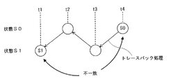
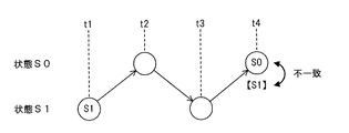
以下、本発明の実施の形態を、図面を参照して説明する。まず、本発明の実施形態における復号化方法の特徴を、図16および図17を用いて説明する。図16は、対比例としての従来の復号方法の問題点を示す図であり、図17は、本発明の実施形態の復号方法の特徴を説明するための図である。図16および図17では、説明の便宜を考慮して、トレリス図における一つの生き残りパスを簡略化して描いてある。なお、図16および図17のトレリス図では、縦軸として2つの状態S0、S1が示され、横軸として時点1〜時点4が示されている。
Hereinafter, embodiments of the present invention will be described with reference to the drawings. First, features of the decoding method according to the embodiment of the present invention will be described with reference to FIGS. 16 and 17. FIG. 16 is a diagram illustrating a problem of the conventional decoding method as a comparative example, and FIG. 17 is a diagram for explaining the characteristics of the decoding method according to the embodiment of the present invention. In FIG. 16 and FIG. 17, for the convenience of explanation, one survivor path in the trellis diagram is illustrated in a simplified manner. In the trellis diagrams of FIGS. 16 and 17, two states S0 and S1 are shown on the vertical axis, and
図16に示すように、従来の復号方法によって巡回畳み込み符号の復号化を行う場合、トレースバックを行わないと、その生き残りパスの、時刻t1における状態が判明しない。 As shown in FIG. 16, when decoding a cyclic convolutional code by a conventional decoding method, the state of the surviving path at time t1 cannot be determined unless traceback is performed.
図16の場合、時刻t1(ACS開始時点)の状態がS1であり、時刻t4(ACS終了時点)の状態はS0であり、不一致であるから、巡回畳み込み符号の条件を満たさない。すなわち、このパスは必ず誤りを含んでいる。したがって、トレースバックで得られた復号データは廃棄されることになり、結果的に、無駄なトレースバック処理が行われたことになる。 In the case of FIG. 16, the state at time t1 (ACS start time) is S1, and the state at time t4 (ACS end time) is S0, which is inconsistent, and therefore does not satisfy the condition of the cyclic convolutional code. That is, this path always includes an error. Therefore, the decoded data obtained by the traceback is discarded, and as a result, useless traceback processing is performed.
一方、図17の本発明の実施形態の復号方法では、トレリス図上で、生き残りパスが更新される毎に、そのパスの時刻t1における状態を示す情報を、そのパスと関連付けして保存していく。図17において、時刻t4の状態(S0)の下に示される記号[S1]は、保存されている時刻t1における状態を示している。 On the other hand, in the decoding method of the embodiment of the present invention shown in FIG. 17, each time a surviving path is updated on the trellis diagram, information indicating the state of the path at time t1 is stored in association with the path. Go. In FIG. 17, the symbol [S1] shown below the state (S0) at time t4 indicates the state at time t1 that is stored.
図17では、トレースバックをしなくても、時刻t1における状態(S1)と時刻t4における状態(S0)が不一致であることが判明する。これにより、このパスには誤りが含まれることがわかり、無駄なトレースバックを回避することができる。つまり、このようなACS開始時点および終了時点における状態が不一致である生き残りパスは、トレースバックの対象から外し、一致が確認されたパスのみをトレースバックの候補とすることで、トレースバックの対象となるパスの数を絞り込むことができる。そして、その候補のパスが複数ある場合には、パスメトリックがより小さなパス(より尤度が高いパス)を優先してトレースバックを行うことで、効率的に復号化処理を行うことができる。 In FIG. 17, it is found that the state (S1) at time t1 and the state (S0) at time t4 do not match without performing traceback. As a result, it can be seen that the path includes an error, and useless traceback can be avoided. In other words, such surviving paths whose states at the ACS start time and end time are inconsistent are excluded from the target of traceback, and only the path that has been confirmed to be matched is set as a traceback candidate. The number of passes can be narrowed down. When there are a plurality of candidate paths, it is possible to efficiently perform the decoding process by performing the traceback by giving priority to a path having a smaller path metric (a path having a higher likelihood).
このように、従来例では、「トレースバック処理が、ACS開始時点の状態を特定する手段としても使われていた」ため、無駄なトレースバック処理が発生する確率が高い。これに対し、本発明では、「ACS開始時点の状態を各生き残りパスと関連づけて保存する構成を採用した」ため、ACS開始時点の状態をトレースバック前に特定することができるようになり、これにより、無駄なトレースバックを回避できるようになり、復号化処理の大幅な効率化が達成される。 In this way, in the conventional example, “the traceback process is also used as a means for specifying the state at the start of the ACS”, and thus there is a high probability that a useless traceback process will occur. On the other hand, in the present invention, “the configuration in which the state at the ACS start time is stored in association with each surviving path is adopted”, the state at the ACS start time can be specified before the traceback. As a result, it is possible to avoid useless traceback and to achieve significant efficiency of the decoding process.
(第1の実施形態)
まず、図1〜図6を参照しながら、本発明の第1の実施形態の説明をする。図1(a)は誤り訂正符号化装置のブロック図、図1(b)は本発明の実施形態の誤り訂正復号化装置のブロック図、図2は本発明の実施形態のビタビ復号方法におけるACS処理を詳細に説明するための図、図3は本発明の実施形態のビタビ復号方法におけるトレースバック処理の処理手順を示すフローチャートである。
(First embodiment)
First, the first embodiment of the present invention will be described with reference to FIGS. 1A is a block diagram of an error correction coding apparatus, FIG. 1B is a block diagram of an error correction decoding apparatus of an embodiment of the present invention, and FIG. 2 is an ACS in a Viterbi decoding method of an embodiment of the present invention. FIG. 3 is a flowchart for explaining the processing in detail, and FIG. 3 is a flowchart showing the processing procedure of the traceback processing in the Viterbi decoding method of the embodiment of the present invention.
なお、トレースバック処理は、ハードウェアによる回路やソフトウェアによって実現することが可能である。 The traceback process can be realized by a hardware circuit or software.
また、図4は本実施形態のビタビ復号方法及び誤り訂正復号化回路を適用するトレリス図の例1、図5は本実施形態を適用するトレリス図の例2、図6は本実施形態を適用するトレリス図の例3をそれぞれ示す。 4 shows an example 1 of a trellis diagram to which the Viterbi decoding method and the error correction decoding circuit of the present embodiment are applied, FIG. 5 shows an example 2 of a trellis diagram to which the present embodiment is applied, and FIG. 6 applies the present embodiment. Example 3 of the trellis diagram is shown respectively.
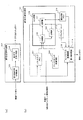
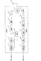
図1(a)において、参照符号101は誤り訂正符号化装置、102は誤り訂正復号化装置である。誤り訂正符号化装置101は、情報ビットにCRC符号等の誤り検出符号を付加する誤り検出符号付加回路103と、誤り検出符号を付加したビット列を巡回畳み込み符号化して送信する誤り訂正符号化回路104を備える。
In FIG. 1A, reference numeral 101 is an error correction coding apparatus, and 102 is an error correction decoding apparatus. An error correction coding apparatus 101 includes an error detection
また、図1(b)において、誤り訂正復号化装置102は、ブランチメトリック計算回路106、パスメトリックメモリ107、加算器108、比較器109、開始状態メモリ110、選択器111、パスメモリ112およびトレースバック制御回路113(誤り検出回路114を内蔵する)を備える。なお、ACS回路105は加算器108、比較器109及び選択器111を有して構成されている。
1B, the error
開始状態メモリ110が設けられたことによって、ACS開始時点の状態を、各生き残りパスと関連づけて保存できるようになっている点が、この誤り訂正符号化装置102の大きな特徴である。
The fact that the
ブランチメトリック計算手段の機能を有するブランチメトリック計算回路106には、例えばブランチメトリックにハミング距離を用いた硬判定を採用する場合には、処理時点毎に受信データの1時点分のビットが入力される。
For example, when a hard decision using a Hamming distance is adopted for the branch metric, the bit corresponding to one time point of the received data is input to the branch
いま、ブランチメトリック計算回路106が上述の図9の符号化器に対応するものであれば、各処理時点毎に2ビット(X1、X2に対応)が入力される。ブランチメトリック
計算回路106では、現時点の受信ビットの内容に基づいてブランチメトリックが計算され、加算器108に入力される。
If the branch
なお、本実施形態ではハミング距離を用いた硬判定によって説明するが、ブランチメトリック計算回路に軟判定情報を用いる場合には、ブランチメトリック計算回路106には、処理時点毎に受信データ1時点分の軟判定情報が入力される。
In this embodiment, the hard decision using the Hamming distance will be described. However, when soft decision information is used for the branch metric calculation circuit, the branch
パスメトリックメモリ107には、各状態について、現時点までの生き残りパスのパスメトリックが格納されている。
The path
加算器108では、パスメトリックメモリ107から読み出した各状態の現時点までの生き残りパスのパスメトリックに、ブランチメトリック計算回路106で計算されたブランチメトリックが加算され、次時点の各状態に至るパスメトリックが算出され、比較器109及び選択器111に入力される。
In the
なお、次時点のある状態に至るパスは複数存在するため、加算器108から出力されるパスメトリックは1時点1状態の演算ごとに複数存在する。
Since there are a plurality of paths that reach a certain state at the next time point, a plurality of path metrics output from the
比較器109では、各状態について、加算器108から入力された複数のパスメトリックが比較され、最も尤度の高いパスの選択信号が選択器111に出力されると共に、そのパスの選択信号がパスメモリ112に格納される。
The
開始状態記憶手段の機能を有する開始状態メモリ110には、各状態について、現時点までの生き残りパスのACS演算開始時点(時点S)における状態番号が格納されている。
In the
生き残りパス選択手段の機能を有する選択器111では、各状態について、比較器109から入力されたパス選択信号に基づいて、加算器108から入力されたパスメトリックの中から最も尤度の高いパスが選択され、選択されたパスメトリックはパスメトリックメモリ107に出力され、パスメトリックメモリ107の内容は更新される。
In the
さらに、選択器111では、各状態について、比較器109から入力されたパス選択信号に基づいて、選択されたパスの現時点のACS演算開始時点(時点S)の状態番号が、開始状態メモリ110から読み出され、この状態番号は、次時点のACS演算開始時点(時点S)の状態番号とされ、開始状態メモリ110の内容が更新される。
Further, in the
パスメモリ112には、上述のように、各時点でのパス選択信号が格納されている。
The
ACS演算が終了し、全状態・全時点のパス選択信号がパスメモリ112に格納され、全状態のACS演算開始時点(時点S)の状態番号が開始状態メモリ110に格納された後、トレースバック手段であるトレースバック制御回路113の動作が開始され、復号ビット列が得られる。トレースバックは、開始状態メモリ110に格納された内容と、パスメモリ112に格納された内容に基づき行われる。
After the ACS calculation is completed, the path selection signals for all states and all times are stored in the
次に、以上のような各機能部106〜113からなる誤り訂正復号化装置の動作、すなわち本実施形態のビタビ復号方法について、ACS処理とトレースバック処理に分けて説明する。
Next, the operation of the error correction decoding apparatus including the
ここでは、受信データは巡回畳み込み符号化されており、且つ符号化器の初期状態は不明であることを前提とし、ブランチメトリックにはハミング距離を用いて説明する。 Here, it is assumed that the received data is cyclic convolutionally encoded and the initial state of the encoder is unknown, and the branch metric will be described using a Hamming distance.
また、送信側の入力の情報ビット列Uは、U[0:5]=(1、1、0、0、1、0)の6ビットとし(誤り訂正復号化装置102側では未知)、巡回畳み込み符号化の方法(生成多項式等)は背景技術に示したものと同−とする。さらに受信ビット列Yは硬判定されており、Y[0:11]=(0、0、1、0、1、1、1、1、1、0、0、1)の12ビットとする。
The input information bit string U on the transmission side is 6 bits U [0: 5] = (1, 1, 0, 0, 1, 0) (unknown on the error
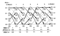
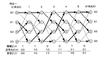
まず、時点0(=時点S)から時点1にかけて行われるACS処理について、図2のトレリス図を参照しながら説明する。
First, ACS processing performed from time 0 (= time S) to
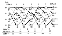
図2の各ノード内の数値は各時点各状態におけるパスメトリックである。また、各ノード下の括弧内の数値*は、各時点各状態における開始状態メモリ110の内容であり、選択されたパスのACS演算開始時点(時点S)の状態番号を示している。
The numerical value in each node in FIG. 2 is a path metric at each time point. A numerical value * in parentheses below each node is the contents of the
時点0では、符号化器の初期状態が不明であるので、各状態の尤度は全て同−であり、PM0(0)=PM1(0)=PM2(0)=PM3(0)=0である。また、状態iにおける開始状態メモリ110の内容をS、S[i]と表すと、時点0の開始状態番号は状態番号そのものであるから、SS[0]=0、SS[1]=1、SS[2]=2、SS[3]=3が開始状態メモリ110の初期値となる。
At
以下、ACSの説明では、ブランチメトリックの計算、パスメトリックの計算及び生き残りパスの選択の方法については、背景技術の説明で図14を用いて行っており全く同一であるため省略する。 Hereinafter, in the description of ACS, the branch metric calculation, path metric calculation, and surviving path selection method are the same as those in FIG.
本実施形態が図14の背景技術と異なるのは、選択器111によって、具備された開始状態メモリ110の内容が更新される点である。
This embodiment is different from the background art of FIG. 14 in that the contents of the
時点1の状態S0においては、時点0(=時点S)で状態S0を開始状態とするパスを選択していることから、時点1における新たな開始状態メモリ110の内容は、SSR[0]=SS[0]=0となる。
In the state S0 at the
時点1の状態S1においては、時点0(=時点S)で状態S2を開始状態とするパスを選択していることから、時点1における新たな開始状態メモリ110の内容は、SSR[1]=SS[2]=2となる。
In the state S1 at the
時点1の状態S2においては、時点0(=時点S)で状態S1を開始状態とするパスを選択していることから、時点1における新たな開始状態メモリ110の内容は、SSR[2]=SS[1]=1となる。
In the state S2 at the
時点1の状態S3においては、時点0(=時点S)で状態S1を開始状態とするパスを選択していることから、時点1における新たな開始状態メモリ110の内容は、SSR[3]=SS[1]=1となる。
In the state S3 at the
このようにして、時点1の全ての状態S0〜S3についての新たな開始状態メモリの内容を抽出した後に、開始状態メモリ110の内容SS[0:3]を更新する。すなわち、SS[0]=SSR[0]=0、SS[1]=SSR[1]=2、SS[2]=SSR[2]=1、SS[3]=SSR[3]=1とする。
In this way, after extracting the contents of the new start state memory for all the states S0 to S3 at
以上が、時点0(=時点S)から時点1にかけて行われるACS処理である。
The above is the ACS processing performed from time 0 (= time S) to
以下、時点1から時点2にかけてのACS処理、時点2から時点3にかけてのACS処理を順次実行していき、時点5から時点6(=時点E)にかけてのACS処理までを終了すると、図4のようなトレリス図が得られる(ACS処理の比較(Compare)において、到達する2つのパスのパスメトリックが同じ値であるときには、状態番号がより小さい状態から至るパスを生き残りパスとした場合)。
Hereinafter, the ACS processing from the
図4おける太線の矢印は生き残りパスである。なお、パス選択情報はSi(t)(i=0〜3、t=1〜6)の各時点各状態の全てにおいて記憶しておく。また、ACS処理終了後の開始状態メモリ内容は、時点6(=時点E)を参照することで、SS[0]=2、SS[1]=2、SS[2]=2、SS[3]=1となっている。 The thick arrow in FIG. 4 is the survival path. The path selection information is stored in all states at each time point of Si (t) (i = 0 to 3, t = 1 to 6). In addition, the contents of the start state memory after the ACS processing is finished are referred to time point 6 (= time point E), so that SS [0] = 2, SS [1] = 2, SS [2] = 2, SS [3 ] = 1.
最終時点である時点EまでACS処理が終了した後、トレースバック処理が開始され、トレースバック処理の結果として復号ビット列が得られる。巡回畳み込み符号化では、最終時点Eにおける状態は不明であるが、初期時点Sと最終時点Eの状態番号が同一になるようにしている。 After the ACS processing is completed until time E, which is the final time, the traceback processing is started, and a decoded bit string is obtained as a result of the traceback processing. In cyclic convolutional coding, the state at the final time point E is unknown, but the initial time point S and the final time point E have the same state number.
すなわち、少なくともトレースバック開始時点(時点E)とトレースバックの終了時点(時点S)における状態が同一でなければ、復号ビット列には誤りビットが必ず含まれることになる。 That is, if the states at least at the trace back start time (time E) and the trace back end time (time S) are not the same, the decoded bit string always includes an error bit.
従って、ACS処埋が終了した後の各状態iに対する開始状態メモリ110の内容SS[i]について、SS[i]=i(i=0〜3)が満たされていない生き残りパスについては、トレースバックをするまでもなく誤ったパスであることがわかるため、トレースバックの必要はない。
Therefore, with respect to the contents SS [i] of the
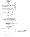
以下、トレースバック制御回路113におけるトレースバック処理について、図3のトレースバック処理の処理手順を示すフローチャートを用いて説明する。
Hereinafter, the traceback processing in the
まず、各状態iについて、開始状態SS[i]を調べる。SS[i]=iであれば、当該状態に至るパスの初期時点Sと最終時点Eの状態が同じであり、パスが正しいための必要条件を満たしている。そこで、状態iをトレースバック開始状態の候補とする(ステップS301)。 First, for each state i, the start state SS [i] is examined. If SS [i] = i, the initial time point S and the final time point E of the path reaching the state are the same, and the necessary condition for the path to be correct is satisfied. Therefore, the state i is set as a traceback start state candidate (step S301).
次に、Nに上記で候補としたトレースバック開始状態の候補数をセットする(ステップS302)。 Next, N is set to the number of candidates for the trace back start state that are candidates as described above (step S302).
もし、Nが0であれば、正しいパスが存在しないため、当該フレームはエラーとし、トレースバックを行わずに処理を終了する(ステップS303、ステップS309)。 If N is 0, there is no correct path, so the frame is regarded as an error, and the process is terminated without performing traceback (steps S303 and S309).
ステップS303でNが0以外であれば、ステップS304〜ステップS307のkのループを実行する。 If N is not 0 in step S303, the loop k in steps S304 to S307 is executed.
まず、トレースバック開始状態の候補のN状態の中から、パスメトリックが最も小さい状態からトレースバックを開始する(ステップS304でk=1、ステップS305)。 First, the traceback is started from the state with the smallest path metric from among the N states of the traceback start state candidates (k = 1 in step S304, step S305).
上記トレースバックによって得られたビット列に付加されている誤り検出符号(例えばCRC符号)を用いて、該ビット列が正しいかどうか調べる(ステップS306)。 Whether or not the bit string is correct is checked using an error detection code (for example, CRC code) added to the bit string obtained by the traceback (step S306).
ステップS306で、該ビット列に誤りがないと判定された場合には、このトレースバックで得られたビット列を復号ビット列Dとし、処理を終了する(ステップS308)。 If it is determined in step S306 that there is no error in the bit string, the bit string obtained by this traceback is set as the decoded bit string D, and the process is terminated (step S308).
ステップS306で、該ビット列に誤りがあると判定され、かつk<Nの場合には、kのループの先頭に戻り、トレースバック開始状態の候補のN状態の中から、パスメトリックが次に小さい状態からトレースバックを開始する(ステップS304でk=2、ステップS305)。 In step S306, if it is determined that there is an error in the bit string and k <N, the process returns to the top of the loop of k, and the path metric is the next smallest among the N states of the traceback start state candidates. Trace back is started from the state (k = 2 in step S304, step S305).
ステップS306で誤りが存在する限りは、最大でN回、ステップS304〜ステップS307のkのループを実行する。 As long as there is an error in step S306, the loop of k from step S304 to step S307 is executed a maximum of N times.
ステップS306で、該ビット列に誤りがあると判定され、かつk=Nの場合には、正しいパスが存在しないため、当該フレームはエラーとし(ステップS309)、処理を終了する。 If it is determined in step S306 that there is an error in the bit string and k = N, there is no correct path, so the frame is regarded as an error (step S309), and the process is terminated.
以上が、トレースバック制御回路113におけるトレースバック処理であるが、これを図4のトレリス図(本発明の実施形態のビタピ復号方法及び誤り訂正復号化回路を適用するトレリス図の例1)に当てはめ、図3のフローチャートを実行すると次のようになる。
The above is the traceback processing in the
まず、ステップS301の処理では、最終時点Eの各状態S0〜S3について、ACS一演算開始時点(時点S)の開始状態SSを調べる。時点Eで状態S0に到達したパスのACS開始状態は、開始状態メモリSS[0]=2を参照することで状態S2であるが、S0≠S2であり状態番号が異なるため、状態S0はトレースバック開始の候補状態とはしない。 First, in the process of step S301, for each state S0 to S3 at the final time point E, the start state SS at the ACS one calculation start time point (time point S) is examined. The ACS start state of the path that has reached state S0 at time E is state S2 by referring to start state memory SS [0] = 2, but since S0 ≠ S2 and the state numbers are different, state S0 is traced. It is not considered as a candidate for starting back.
時点Eで状態S1に到達したパスのACS開始状態は、開始状態メモリSS[1]=2を参照することで状態S2であるが、S1≠S2であり状態番号が異なるため、状態S1はトレースバック開始の候補状態とはしない。 The ACS start state of the path that has reached state S1 at time E is state S2 by referring to start state memory SS [1] = 2, but state S1 is traced because S1 ≠ S2 and the state numbers are different. It is not considered as a candidate for starting back.
時点Eで状態S2に到達したパスのACS開始状態は、開始状態メモリSS[2]=2を参照することで状態S2であり、状態番号がともにS2で一致しているため、状態S2をトレースバック開始の候補状態とする。 The ACS start state of the path that has reached the state S2 at the time point E is the state S2 by referring to the start state memory SS [2] = 2, and since the state numbers are the same in S2, the state S2 is traced. It is set as a candidate state for back start.
時点Eで状態S3に到達したパスのACS開始状態は、開始状態メモリSS[3]=1を参照することで状態S1であるが、S3≠S1であり状態番号が異なるため、状態S3はトレースバック開始の候補状態とはしない。 The ACS start state of the path that has reached the state S3 at the time point E is the state S1 by referring to the start state memory SS [3] = 1, but since S3 ≠ S1 and the state numbers are different, the state S3 is traced. It is not considered as a candidate for starting back.
上記よりトレースバック開始状態の候補は、状態S2の1つであるから、トレースバック開始候補数はN=1となる(ステップS302)。 As described above, since the traceback start state candidate is one of the state S2, the number of traceback start candidates is N = 1 (step S302).
以下、ステップS303以降を実行すると、トレースバック開始状態の候補は状態S2のみであるため、状態S2からトレースバックを行うと、6ビットのビット列(1、1、0、0、1、0)が得られる。このビット列を、図1のトレースバック制御回路113に内蔵される誤り検出回路114が、誤り検出符号を用いてチェックし、誤りがなければ、この6ビットを復号ビット列Dとする。
Hereinafter, when step S303 and subsequent steps are executed, the only candidate for the traceback start state is the state S2. Therefore, when the traceback is performed from the state S2, a 6-bit bit string (1, 1, 0, 0, 1, 0) is obtained. can get. The
実際、入力の情報ビット列Uは、U[0:5]=(1、1、0、0、1、0)であったので、この復号ビット列は正しいものとなっている。 Actually, since the input information bit string U is U [0: 5] = (1, 1, 0, 0, 1, 0), this decoded bit string is correct.
以上の説明のように、図4のトレリス図に本実施形態を適用すると、トレースバックを行う回数は1回である。これに対し、背景技術で説明した第1の従来例(時点Eでパスメトリックが小さい状態から優先的にトレースバックする)ではトレースバック回数が2回、第2の従来例ではトレースバック回数が3回であったため、本発明の実施形態の方法ではトレースバック回数を減らすことができ、短時間で正しい復号ビット列を得ることが可能になることがわかる。 As described above, when the present embodiment is applied to the trellis diagram of FIG. 4, the number of times of performing traceback is one. In contrast, in the first conventional example described in the background art (the traceback is preferentially performed from a state where the path metric is small at the time point E), the number of tracebacks is 2, and in the second conventional example, the number of tracebacks is 3. Therefore, it can be seen that the method of the embodiment of the present invention can reduce the number of tracebacks and can obtain a correct decoded bit string in a short time.
さて、図4のトレリス図は、ACS処理の比較(Compare)において、到達する2つのパスのパスメトリックが同じ値であるときには、状態番号がより小さい状態から至るパスを生き残りパスとした場合に得られるものであった。このように複数のパスの尤度(パスメトリック)が同じときの生き残りパスの選択方法としては、ランダムに選択する方法も考えられる。 The trellis diagram of FIG. 4 is obtained when the path metric of the two paths to be reached has the same value in the comparison of ACS processing (Compare), and the path from the state with the smaller state number is the surviving path. It was In this way, as a method for selecting a surviving path when a plurality of paths have the same likelihood (path metric), a method of selecting at random may be considered.
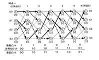
図5のトレリス図(本実施形態のビタビ復号方法及び誤り訂正復号化回路を適用するトレリス図の例2)は、複数のパスの尤度が同じときの生き残りパスがランダムに選択された場合の例であり、図4と比較して時点5から時点6(時点E)に至る過程のみが異なっている。
The trellis diagram of FIG. 5 (example 2 of the trellis diagram to which the Viterbi decoding method and the error correction decoding circuit of the present embodiment are applied) is a case where a surviving path is randomly selected when the likelihood of a plurality of paths is the same. This is an example, and only the process from
すなわち、図5において、時点6状態S0に至る2つのパスにおいて、時点5状態S0から至るパスのパスメトリックは3、時点5状態S2から至るパスのパスメトリックも3であり同じ値であることから、生き残りパスがランダムに選択され、結果として時点5状態S2から至るパスが生き残りパスとなったものである(図4では、時点5状態S0から至るパスを生き残りパスとしている)。
That is, in FIG. 5, the path metric of the path from the
この図5についても本発明の実施形態のトレースバック処理に当てはめ、図3のフローチャートを実行すると次のようになる。 This FIG. 5 is also applied to the traceback processing of the embodiment of the present invention, and the flowchart of FIG. 3 is executed as follows.
まず、ステップS301の処理では、最終時点Eの各状態S0〜S3について、ACS演算開始時点(時点S)の開始状態SSを調べる。時点Eで状態S0に到達したパスのACS開始状態は、開始状態メモリSS[0]=0を参照することで状態S0であり、状態番号がともにS0で一致しているため、状態S0をトレースバック開始の候補状態とする。 First, in the process of step S301, for each state S0 to S3 at the final time point E, the start state SS at the ACS calculation start time point (time point S) is examined. The ACS start state of the path that has reached the state S0 at the time point E is the state S0 by referring to the start state memory SS [0] = 0, and since the state numbers are the same in S0, the state S0 is traced. It is set as a candidate state for back start.
時点Eで状態S1に到達したパスのACS開始状態は、開始状態メモリSS[1]=2を参照することで状態S2であるが、S1≠S2であり状態番号が異なるため、状態S1はトレースバック開始の候補状態とはしない。 The ACS start state of the path that has reached state S1 at time E is state S2 by referring to start state memory SS [1] = 2, but state S1 is traced because S1 ≠ S2 and the state numbers are different. It is not considered as a candidate for starting back.
時点Eで状態S2に到達したパスのACS開始状態は、開始状態メモリSS[2]=2を参照することで状態S2であり、状態番号がともにS2で一致しているため、状態S2をトレースバック開始の候補状態とする。 The ACS start state of the path that has reached the state S2 at the time point E is the state S2 by referring to the start state memory SS [2] = 2, and since the state numbers are the same in S2, the state S2 is traced. It is set as a candidate state for back start.
時点Eで状態S3に到達したパスのACS開始状態は、開始状態メモリSS[3]=1を参照することで状態S1であるが、S3≠S1であり状態番号が異なるため、状態S3はトレースバック開始の候補状態とはしない。 The ACS start state of the path that has reached the state S3 at the time point E is the state S1 by referring to the start state memory SS [3] = 1, but since S3 ≠ S1 and the state numbers are different, the state S3 is traced. It is not considered as a candidate for starting back.
上記よりトレースバック開始状態の候補は、状態S0と状態S2の2つであるから、トレースバック開始候補数はN=2となる(ステップS302)。 From the above, since there are two candidates of the traceback start state, the state S0 and the state S2, the number of traceback start candidates is N = 2 (step S302).
以下、ステップS303以降を実行する。 Thereafter, step S303 and subsequent steps are executed.
ステップS305を初めて実行するとき、k=1である。このときステップS305は、『トレースバック開始状態の候補の(N=)2状態の中で、パスメトリックが(k=)1番目小さい状態からトレースバックを開始する』となる。トレースバック開始状態の候補は状態S0と状態S2であるが、状態S0に至るパスのパスメトリックは“3”であるのに対し、状態S2に至るパスのパスメトリックは“2”であるから、よりパスメトリックの小さい状態S2からトレースバックを開始すればよい。 When step S305 is executed for the first time, k = 1. At this time, the step S305 becomes “Start traceback from a state where the path metric is (k =) the first smallest among the (N =) 2 states which are candidates for the traceback start state”. The traceback start state candidates are the state S0 and the state S2, but the path metric of the path leading to the state S0 is “3”, whereas the path metric of the path leading to the state S2 is “2”. Trace back may be started from the state S2 having a smaller path metric.
状態S2からトレースバックを行うと、6ビットのビット列(1、1、0、0、1、0)が得られる。このビット列を誤り検出符号によってチェックし誤りがなければ、この6ビットを復号ビット列Dとする。実際、入力情報ビット列Uは、U[0:5]=(1、1、0、0、1、0)であったので、この復号ビット列は正しいものとなっている。 When trace back is performed from the state S2, a 6-bit bit string (1, 1, 0, 0, 1, 0) is obtained. This bit string is checked by an error detection code. If there is no error, these 6 bits are set as a decoded bit string D. Actually, since the input information bit string U is U [0: 5] = (1, 1, 0, 0, 1, 0), this decoded bit string is correct.
以上の説明では、トレースバック回数は1回であったが、もし状態S0(状態S0に至るパスのパスメトリックは“3”)と状態S2(状態S2に至るパスのパスメトリックは“2”)のトレースバック開始候補のうち、パスメトリックが大きい状態S0からトレースバックを開始すると、トレースバック回数は2回となってしまい、回数が増えてしまう(状態S0に至るパスから得られるビット列は、ステップS306の誤り検出で誤りありと判定され、k=2のステップS305で状態S2から2回目のトレースバックが行われる)。 In the above description, the number of tracebacks is one, but if the state S0 (the path metric of the path leading to the state S0 is “3”) and the state S2 (the path metric of the path leading to the state S2 is “2”) If the traceback is started from the state S0 having a large path metric, the number of tracebacks becomes 2, and the number of times increases (the bit string obtained from the path leading to the state S0 It is determined that there is an error in the error detection in S306, and the second traceback is performed from the state S2 in step S305 of k = 2).
このように、トレリス図上の生き残りパスについて、ACSの開始時点Sと終了時点Eの状態が同一であるパスが複数存在する場合には、ビタビ復号においてはパスメトリックが小さい(尤度が高い)パスの方が正しい確率が高いという性質を利用し、その状態に至るパスを優先的にトレースバックすることで、より短時間で正しい復号ビット列が得ることが可能となる。 As described above, regarding the surviving paths on the trellis diagram, when there are a plurality of paths having the same ACS start time S and end time E, the path metric is small in Viterbi decoding (high likelihood). By utilizing the property that a path has a higher probability of being correct and tracing back the path leading to that state preferentially, a correct decoded bit string can be obtained in a shorter time.
さらに、別の例として、受信ビット列Yが硬判定されており、Y[0:11]=(0、0、1、0、1、1、1、1、1、0、1、0)の12ビットが誤り訂正復号化装置102に入力され、トレリス図が図6(本発明の実施形態のビタビ復号方法及び誤り訂正復号化回路を適用するトレリス図の例3)に示すものになった場合を考える(入力の情報ビット列Uや畳み込み符号の生成多項式等はこれまでの説明と同一である)。なお、図6はACS処理の比較(Compare)において、到達する2つのパスのパスメトリックが同じ値であるときには、状態番号がより小さい状態から至るパスを生き残りパスとした場合に得られるものである(図6は図4と比較してY[10:11]のみが違うため、時点5から時点6(時点E)に至る過程のみが異なっている)。
As another example, the received bit string Y is hard-decided, and Y [0:11] = (0, 0, 1, 0, 1, 1, 1, 1, 1, 0, 1, 0). When 12 bits are input to the error
この図6についても本発明の実施形態のトレースバック処理に当てはめ、図3のフローチャートを実行すると次のようになる。 This FIG. 6 is also applied to the traceback processing of the embodiment of the present invention, and the flowchart of FIG. 3 is executed as follows.
まず、ステップS301の処理では、最終時点Eの各状態S0〜S3について、ACS演算開始時点(時点S)の開始状態SSを調べる。時点Eで状態S0に到達したパスのACS開始状態は、開始状態メモリSS[0]=2を参照することで状態S2であるが、S0≠S2であり状態番号が異なるため、状態S0はトレースバック開始の候補状態とはしない。 First, in the process of step S301, for each state S0 to S3 at the final time point E, the start state SS at the ACS calculation start time point (time point S) is examined. The ACS start state of the path that has reached state S0 at time E is state S2 by referring to start state memory SS [0] = 2, but since S0 ≠ S2 and the state numbers are different, state S0 is traced. It is not considered as a candidate for starting back.
時点Eで状態S1に到達したパスのACS開始状態は、開始状態メモリSS[1]=2を参照することで状態S2であるが、S1≠S2であり状態番号が異なるため、状態S1はトレースバック開始の候補状態とはしない。 The ACS start state of the path that has reached state S1 at time E is state S2 by referring to start state memory SS [1] = 2, but state S1 is traced because S1 ≠ S2 and the state numbers are different. It is not considered as a candidate for starting back.
時点Eで状態S2に到達したパスのACS開始状態は、開始状態メモリSS[2]=1を参照することで状態S1であるが、S2≠S1であり状態番号が異なるため、状態S2はトレースバック開始の候補状態とはしない。 The ACS start state of the path that has reached the state S2 at the time E is the state S1 by referring to the start state memory SS [2] = 1. However, since S2 ≠ S1 and the state numbers are different, the state S2 is traced. It is not considered as a candidate for starting back.
時点Eで状態S3に到達したパスのACS開始状態は、開始状態メモリSS[3]=2を参照することで状態S2であるが、S3≠S2であり状態番号が異なるため、状態S3はトレースバック開始の候補状態とはしない。 The ACS start state of the path that has reached the state S3 at the time point E is the state S2 by referring to the start state memory SS [3] = 2, but since S3 ≠ S2 and the state numbers are different, the state S3 is traced. It is not considered as a candidate for starting back.
上記よりトレースバック開始状態の候補は、ひとつも存在しないため、トレースバック開始候補数はN=0となる(ステップS302)。 As described above, since there is no traceback start candidate, the number of traceback start candidates is N = 0 (step S302).
ステップS303では、N=0のため、ステップS309に移行する。ステップS309では、正しい生き残りパスが存在しないとして当該フレームをフレームエラーと判定し、トレースバックを終了する。 In step S303, since N = 0, the process proceeds to step S309. In step S309, it is determined that there is no correct surviving path, the frame is determined to be a frame error, and the traceback is terminated.
以上の説明のとおり、図6のトレリス図に、本実施形態を適用すると、トレースバックを行う回数は0回であり、トレースバックを行わなくとも当該受信ビット列は誤り訂正復号が不可能であることが判定できるといった効果がある。 As described above, when this embodiment is applied to the trellis diagram of FIG. 6, the number of times of performing traceback is 0, and the received bit string cannot be subjected to error correction decoding without performing traceback. There is an effect that can be determined.
これに対し、背景技術で説明した第1の従来例を図6のトレリス図に適用した場合、時点Eにおいて状態S2のパスメトリックが“1”で最も小さい(尤度が高い)ため、状態S2からトレースバックをするが、この結束得られるビット列は誤りである。 On the other hand, when the first conventional example described in the background art is applied to the trellis diagram of FIG. 6, the state S2 has the smallest path metric “1” at time E (highest likelihood). Traceback is performed from this point, but the bit string obtained from this binding is incorrect.
以下、他のどの状態からトレースバックを開始しても、得られるビット列は全て誤りとなり、処理が無駄になってしまう。 Hereinafter, even if traceback is started from any other state, all the obtained bit strings become errors, and processing is wasted.
また、背景技術で説明した第2の従来例を図6のトレリス図に適用した場合を考える。 Consider the case where the second conventional example described in the background art is applied to the trellis diagram of FIG.
図6の時点Eにおいて状態S2のパスメトリックが“1”で最も小さい(尤度が高い)ため、状態S2から1回目のトレースバックを開始する。この1回目のトレースバックでは、終了時点(時点S)において状態S1に到達することから、状態S2≠状態S1により、得られた復号ビット列には誤りが含まれる。このため2回目のトレースバックを行う。 Since the path metric of state S2 is “1” which is the smallest (high likelihood) at time E in FIG. 6, the first traceback is started from state S2. In the first traceback, since the state S1 is reached at the end time point (time point S), an error is included in the obtained decoded bit string due to the state S2 ≠ the state S1. For this reason, a second traceback is performed.
2回目のトレースバックでは、1回目のトレースバックの終了時点(時点S)の状態S1を新しい開始状態としてトレースバックを行う。この2回目のトレースバックでは、終了時点(時点S)において状態S2に到達することから、状態S1≠状態S2により、得られた復号ビット列には誤りが含まれる。 In the second traceback, the traceback is performed with the state S1 at the end of the first traceback (time point S) as a new start state. In the second traceback, since the state S2 is reached at the end point (time point S), an error is included in the obtained decoded bit string due to the state S1 ≠ the state S2.
以後、同様にトレースバックを続けても正しいパスは見付からず、トレースバックの開始状態が、状態S2→状態S1→状態S2→状態S1→・・・を繰り返すだけとなってしまい、処理は無駄となってしまう。 Thereafter, even if traceback is continued in the same manner, a correct path is not found, and the traceback start state only repeats state S2, state S1, state S2, state S1, and so on, and the processing is wasted. turn into.
これを回避するために従来の技術2では、トレースバック回数の制限を加えているが、もし正しいパスが存荏した場合においては、正しいパス(復号ビット列)があるにも関わらず、トレースバックを行わないがために、正しい結果が破棄されてしまう場合がある。
In order to avoid this, the
巡回畳み込み符号化では、トレースバックの開始時点(時点E)と終了時点(時点Sにおける状態が異なる場合には、復号ビット列が正しいことはないが、上述の通り従来例のビタビ復号方法では、そのような場合にもトレースバックを行ってしまうため、処理そのものが無駄になることが多い。 In cyclic convolutional coding, when the traceback start time (time E) and end time (states at time S are different, the decoded bit string is not correct. However, as described above, in the Viterbi decoding method of the conventional example, In such a case, since the traceback is performed, the processing itself is often wasted.
以上に説明したように、本発明の実施形態のビタビ復号方法及び誤り訂正復号化装置では、巡回畳み込み符号化の性質を利用し、ACS演算終了時点(時点E)において、全ての状態の生き残りパスについてACS演算開始時点(時点S)における開始状態を記憶していることから、巡回畳み込み符号によって得られるパスの性質である(符号器の初期時点の状態)=(符号器の最終時点の状態)を利用することができ、トレースバックを行わずしてパス(復号ビット列)の誤りを検出可能となるため、トレースバック回数を大きく減らすことができるという利点がある。また少ないトレースバック回数で正しい復号ビット列が得られる可能性が高くなるという効果がある。 As described above, in the Viterbi decoding method and the error correction decoding apparatus according to the embodiment of the present invention, the survivor paths of all states are used at the end of the ACS operation (time point E) using the property of cyclic convolutional encoding. Since the start state at the ACS calculation start point (time point S) is stored for, the property of the path obtained by the cyclic convolutional code (the state at the initial point of the encoder) = (the state at the final point of the encoder) Since it is possible to detect a path (decoded bit string) error without performing traceback, there is an advantage that the number of tracebacks can be greatly reduced. In addition, there is an effect that the possibility of obtaining a correct decoded bit string with a small number of tracebacks is increased.
さらに、本発明の実施形態のビタビ復号方法及び誤り訂正復号化装置では、トレースバックを行う回数を減らすことができるため、ハードウェア実現の場合には回路規模を小さく実現でき、またソフトウェア実現の場合には演算量の低減が図られるため、消費電流を小さくできるという効果を得ることができる。 Furthermore, in the Viterbi decoding method and the error correction decoding apparatus according to the embodiment of the present invention, the number of times of traceback can be reduced, so that the circuit scale can be reduced in the case of hardware implementation, and the case of software implementation Since the amount of computation is reduced, the effect of reducing current consumption can be obtained.
(第2の実施の形態)
次に、本発明の実施形態の移動局無線装置、基地局無線装置および移動通信システムについて、図7及び図8を参照しながら説明する。
(Second Embodiment)
Next, a mobile station radio apparatus, a base station radio apparatus, and a mobile communication system according to an embodiment of the present invention will be described with reference to FIGS.
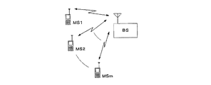
無線通信システムでは、基地局無線装置と移動局無線装置を結ぶ電波の伝搬路状況が劣悪となり、受信側において、送信ビット列を正しく復号することが困難になる状況が多々ある。 In a radio communication system, there are many situations in which the state of the propagation path of a radio wave connecting a base station radio apparatus and a mobile station radio apparatus becomes inferior and it is difficult to correctly decode a transmission bit string on the receiving side.
このような劣悪な伝搬路状況においては、基地局無線装置と移動局無線装置との同期がとれているにも関わらず、正しい復号結果(復号ビット列)を得にくくなる。 In such a poor propagation path situation, it is difficult to obtain a correct decoding result (decoded bit string) even though the base station radio apparatus and the mobile station radio apparatus are synchronized.
上記状況下においては、誤り訂正符号化方式に巡回畳み込み符号化を採用する無線通信システムでは、誤り訂正復号のビタビ復号処理にて、トレースバックを開始する状態を確定することが困難となり、従来の技術においては、正しいパスを抽出するのに時間がかかるため、或いは正しいパスが存在しないにも関わらずトレースバックを行ってしまうため、基地局無線装置、移動局無線装置および移動通信システム全体としての消費電流が増大してしまう。 Under the above circumstances, in a wireless communication system that employs cyclic convolutional coding as an error correction coding method, it is difficult to determine a state in which traceback is started in Viterbi decoding processing of error correction decoding. In the technology, it takes time to extract a correct path, or traceback is performed even if the correct path does not exist. Therefore, the base station radio apparatus, the mobile station radio apparatus, and the mobile communication system as a whole Current consumption increases.
第2の実施形態ではこのような問題点を解決するような移動局無線装置、基地局無線装置および移動通信システムについて説明するものである。 In the second embodiment, a mobile station radio apparatus, a base station radio apparatus, and a mobile communication system that solve such problems will be described.
図7は第2の実施形態の移動局無線装置および基地局無線装置のブロック図である。 FIG. 7 is a block diagram of a mobile station radio apparatus and a base station radio apparatus according to the second embodiment.
まず、図7における送信系について説明する。送信系は図7における符号701〜708に相当する。
First, the transmission system in FIG. 7 will be described. The transmission system corresponds to reference
送信系では、情報ビット列Uは誤り訂正符号化装置701に入力され、巡回畳み込み符号化が行われ、符号化ビット列が出力される。誤り訂正符号化装置701は、図1における誤り訂正符号化装置101に相当するものである。なお、畳み込み符号化は、情報ビット列Uのうち重要度の高いビットにのみ行われることが多い。
In the transmission system, the information bit sequence U is input to the error
誤り訂正符号化装置701から出力された符号化ビット列は、波形生成器702に入力され、制御データが付加され、変調データが生成される。
The encoded bit string output from the error
D/A変換器703では、上記変調データがデジタルからアナログに変換され、さらに、直交変調器704では、アナログに変換されたデータが直交変調される。
In the D /
直交変調器704で直交変調された信号は、所定の送信周波数に変換するミキサ705によってアップコンバートされ、アップコンバートされた信号は増幅器706によって増幅される。
The signal subjected to quadrature modulation by the
増幅された信号は、送受信信号を分岐する共用器707に入力され、送受信共用アンテナ708から無線信号として送信される。
The amplified signal is input to a
次に、図7における受信系について説明する。受信系は図7における符号707〜714に相当する。
Next, the receiving system in FIG. 7 will be described. The reception system corresponds to reference
受信系では、送受信共用アンテナ708及び共用器707を通じて受信された受信信号は、ミキサ709によってダウンコンバートされ、さらに直交復調器710によって直交復調される。
In the reception system, the reception signal received through the transmission / reception shared
直交復調されたアナログ信号は、A/D変換器711によってデジタル信号に変換され、同期部712及びデジタル検波器713に入力される。
The quadrature demodulated analog signal is converted into a digital signal by the A /
同期部712では、上記デジタル信号を用いて同期獲得が行われ、シンボルタイミング信号がデジタル検波器713に入力される。
The
デジタル検波器713では、上記デジタル信号とシンボルタイミング信号を用いてデジタル検波(例えば変調方式がπ/4シフトQPSK方式であれば遅延検波)が行われ、受信データが出力される。
The
受信データは、例えば、誤り訂正復号化装置714で硬判定によるビタビ復号を行う場合にはビット列となり、誤り訂正復号化装置714で軟判定によるビタビ復号を行う場合には信号空間上のI、Q値列となる。
The received data is, for example, a bit string when the Viterbi decoding by the hard decision is performed by the error
上記受信データはさらに誤り訂正復号化装置714に入力され、誤り訂正復号され、復号ビット列Dが得られる。
The received data is further input to an error
誤り訂正復号化装置714は、図1における誤り訂正復号化装置102に相当するものであり、本発明の実施形態のビタビ復号方法や誤り訂正復号化装置が含まれたものである。
The error
誤り訂正復号化装置714からは、同期部712及びデジタル検波器713へフレーム誤り情報が提供される。これによって、フレームが誤った場合には、いち早く次処理に移行することが可能となる。
Frame error information is provided from the error
例えば、移動局無線装置でフレーム誤りが一定回数続いた場合には、デジタル検波器713をすぐにアイドル状態にして消費電流を低減させ、また同期部712にて即座に初期同期獲得を開始することが可能となる。
For example, when a frame error continues for a certain number of times in the mobile station radio apparatus, the
このように構成された本発明の実施形態の移動局無線装置および基地局無線装置によれば、誤り訂正復号化装置714において、第1の実施形態に記載した通りの効果があり、すなわちビタビ復号処理におけるトレースバック回数を大きく減らすことができ、また少ないトレースバック回数で正しい復号ビット列が得られることから、受信性能の良好な移動局無線装置および基地局無線装置が得られるという効果がある。
According to the mobile station radio apparatus and base station radio apparatus of the embodiment of the present invention configured as described above, the error
さらに、本発明の実施形態の移動局無線装置および基地局無線装置では、誤り訂正復号化装置714において、トレースバックを行う回数を減らすことができるため、ハードウエア実現の場合には回路規模を小さく実現でき、またソフトウェア実現の場合には演算量の低減が図られるため、消費電流の小さい装置が実現できるという効果がある。また、少ないトレースバック回数でフレーム誤りが判定可能であるため、いち早く次処理に移行でき、消費電流が小さい装置を構成できるという効果がある。
Furthermore, in the mobile station radio apparatus and the base station radio apparatus according to the embodiment of the present invention, the number of times of performing traceback can be reduced in the error
また、上記の移動局無線装置もしくは基地局無線装置の少なくとも一方を含むような、本発明の実施形態の移動通信システムの構成図を図8に示す。図8では、移動局無線装置MS1、MS2、・・・、MSmおよび基地局無線装置BSのうち、少なくともひとつに図7で構成された装置が含まれているものとする。 FIG. 8 shows a configuration diagram of the mobile communication system according to the embodiment of the present invention including at least one of the mobile station radio apparatus and the base station radio apparatus. In FIG. 8, it is assumed that at least one of the mobile station radio apparatuses MS1, MS2,..., MSm and the base station radio apparatus BS includes the apparatus configured in FIG.
図8の移動通信システムは、図7に示した基地局無線装置および移動局無線装置が複数含まれるように構成されているため、システム全体として受信性能の良好なシステムを構築できるという効果がある。また同様に、消費電流が低減されたシステムを構築できるという効果がある。 The mobile communication system of FIG. 8 is configured to include a plurality of base station radio apparatuses and mobile station radio apparatuses shown in FIG. 7, and therefore, there is an effect that it is possible to construct a system with good reception performance as a whole system. . Similarly, there is an effect that a system with reduced current consumption can be constructed.
以上説明したように、本発明の実施形態によれば、ACS演算終了時点において、全ての状態の生き残りパスについてACS演算開始時点における開始状態を記憶し、巡回畳み込み符号のパスの性質である(符号器の初期時点の状態)=(符号器の最終時点の状態)を利用して一致判定を行うことで、トレースバックを行わずして、そのパス(復号ビット列)が誤りを含むパスであることを検出することができ、したがって、そのようなパスをトレースバックの対象から除外することができる。したがって、トレースバック対象のパスを絞り込むことができ、トレースバック回数を大きく減らすことができる。 As described above, according to the embodiment of the present invention, at the end of the ACS operation, the start state at the start of the ACS operation is stored for all the surviving paths in the state, which is the nature of the path of the cyclic convolutional code (code The state (initial state of the encoder) = (the state of the final point of the encoder) is used to make a match determination, so that the path (decoded bit string) is a path including an error without performing traceback. Therefore, such a path can be excluded from the traceback target. Therefore, the traceback target paths can be narrowed down, and the number of tracebacks can be greatly reduced.
また、本発明の実施形態によれば、少ないトレースバック回数で正しい復号ビット列が得られる可能性が非常に高くなり、効率的、かつ迅速な復号化を行うことができる。
また、本発明によれば、無駄なトレースバック処理(演算処理)がなくなり、したがって、移動体通信機器における回路の消費電力や回路規模の増大を抑制することができる。このことは、良好な移動通信システムの構築に役立つものである。
Further, according to the embodiment of the present invention, there is a very high possibility that a correct decoded bit string can be obtained with a small number of tracebacks, and efficient and quick decoding can be performed.
Further, according to the present invention, useless traceback processing (arithmetic processing) is eliminated, and therefore it is possible to suppress an increase in circuit power consumption and circuit scale in the mobile communication device. This is useful for constructing a good mobile communication system.
本発明は、巡回畳み込み符号の復号化処理を効率化するという効果を奏し、したがって、デジタル移動無線通信システムをはじめとして、誤り訂正符号化に巡回畳み込み符号化を採用する通信システム全般に適用可能である。また、各種記憶装置、記憶媒体においても、誤り訂正符号に巡回畳み込み符号化が採用されていれば、全て適用可能である。 INDUSTRIAL APPLICABILITY The present invention has an effect of improving the efficiency of decoding processing of cyclic convolutional codes, and therefore can be applied to all communication systems that employ cyclic convolutional coding for error correction coding, including digital mobile radio communication systems. is there. Also, in various storage devices and storage media, all can be applied as long as cyclic convolutional coding is adopted as the error correction code.
101 誤り訂正符号化装置
102 誤り訂正復号化装置
103 誤り検出符号付加回路
104 誤り訂正符号化回路
105 ACS回路
106 ブランチメトリック計算回路
107 パスメトリックメモリ
108 加算器
109 比較器
110 開始状態メモリ
111 選択器
112 パスメモリ
113 トレースバック制御回路
114 誤り検出回路
701 誤り訂正符号化装置
702 波形整形器
703 D/A変換器
704 直交変調器
705 ミキサ
706 増幅器
707 共用器
708 送受信共用アンテナ
709 ミキサ
710 直交復調器
711 A/D変換器
712 同期部
713 デジタル検波器
714 誤り訂正復号化装置
DESCRIPTION OF SYMBOLS 101 Error
Claims (7)
加算比較選択演算において、トレリス図上の各状態についての生き残りパスが決まると、それらの生き残りパスの各々に関し、パスの尤度であるパスメトリックを記憶し、かつ、各生き残りパスの加算比較選択演算開始時点における状態を記憶し、この処理を加算比較選択演算の終了時点まで繰り返し行うステップと、
加算比較選択演算が終了すると、前記生き残りパスの各々について、前記加算比較選択演算の終了時点における状態と開始時点における状態の一致/不一致を判定するステップと、
前記判定するステップにおいて一致が確認された生き残りパスのみをトレースバック処理の候補とし、その候補の生き残りパスの少なくとも一つについて、トレースバック処理を実行するステップと、
を有するビタビ復号方法。 Viterbi decoding is performed on the code generated by cyclic convolutional coding to generate a convolutional codeword by inputting an information bit string so that the initial state and the end state of the encoder are the same, and the information bit string is decoded. A Viterbi decoding method for
In the addition comparison selection operation, when the survivor path for each state on the trellis diagram is determined, the path metric that is the likelihood of the path is stored for each of the survivor paths, and the addition comparison selection operation for each survivor path Storing the state at the start time and repeating this process until the end of the addition comparison selection calculation;
When the addition comparison selection calculation is completed, for each of the surviving paths, determining whether the state at the end of the addition comparison selection calculation ends with the state at the start time;
Only the surviving paths for which a match is confirmed in the determining step are set as traceback process candidates, and the traceback process is executed for at least one of the candidate survivor paths;
A Viterbi decoding method comprising:
受信データ列からトレリス図における各ブランチの尤度を計算するブランチメトリック計算手段と、
各時点の各状態に至る複数のパスの尤度を比較し、尤度の最も高いパスを生き残りパスとして選択する加算比較選択演算手段と、
各生き残りパスのパスメトリックを記憶するパスメトリック記憶手段と、
各生き残りパスにおける、加算比較選択演算開始時点の状態を記憶する開始状態記憶手段と、
加算比較選択演算が終了すると、前記開始状態記憶手段に記憶されている各生き残りパスの開始状態を参照し、その生き残りパスの各々について、前記加算比較選択演算の終了時点における状態と開始時点における状態の一致/不一致を判定し、その一致が確認された生き残りパスのみをトレースバック処理の候補とし、その候補の生き残りパスの少なくとも一つについてトレースバック処理を実行し、復号データを得るトレースバック手段と、
前記復号データの誤りを検出する誤り検出手段と、
を備える復号化装置。 A decoding device that performs Viterbi decoding,
Branch metric calculation means for calculating the likelihood of each branch in the trellis diagram from the received data sequence;
An addition comparison / selection calculating means for comparing the likelihood of a plurality of paths to each state at each time point and selecting the path with the highest likelihood as a surviving path;
Path metric storage means for storing the path metric of each surviving path;
Start state storage means for storing the state at the start of the addition comparison selection calculation in each surviving path;
When the addition comparison selection calculation is completed, the start state of each survivor path stored in the start state storage means is referred to, and the state at the end of the addition comparison selection calculation and the state at the start time for each of the survivor paths A traceback means for determining a match / mismatch between the two, determining only the surviving path for which the match is confirmed as a traceback process candidate, executing the traceback process on at least one of the surviving paths of the candidate, and obtaining decoded data; ,
Error detection means for detecting an error in the decoded data;
A decoding device comprising:
Priority Applications (1)
| Application Number | Priority Date | Filing Date | Title |
|---|---|---|---|
| JP2004102520A JP2005294898A (en) | 2004-03-31 | 2004-03-31 | Viterbi decoding method, decoding apparatus, mobile station radio apparatus, base station radio apparatus, and mobile communication system |
Applications Claiming Priority (1)
| Application Number | Priority Date | Filing Date | Title |
|---|---|---|---|
| JP2004102520A JP2005294898A (en) | 2004-03-31 | 2004-03-31 | Viterbi decoding method, decoding apparatus, mobile station radio apparatus, base station radio apparatus, and mobile communication system |
Publications (1)
| Publication Number | Publication Date |
|---|---|
| JP2005294898A true JP2005294898A (en) | 2005-10-20 |
Family
ID=35327400
Family Applications (1)
| Application Number | Title | Priority Date | Filing Date |
|---|---|---|---|
| JP2004102520A Pending JP2005294898A (en) | 2004-03-31 | 2004-03-31 | Viterbi decoding method, decoding apparatus, mobile station radio apparatus, base station radio apparatus, and mobile communication system |
Country Status (1)
| Country | Link |
|---|---|
| JP (1) | JP2005294898A (en) |
Cited By (12)
| Publication number | Priority date | Publication date | Assignee | Title |
|---|---|---|---|---|
| JP2008118327A (en) * | 2006-11-02 | 2008-05-22 | Nec Electronics Corp | Viterbi decoding method |
| JP2009159482A (en) * | 2007-12-27 | 2009-07-16 | Nec Electronics Corp | Decoder and decoding method |
| JP2009246485A (en) * | 2008-03-28 | 2009-10-22 | Kyocera Corp | Reception device and viterbi decoding method |
| JP2009246490A (en) * | 2008-03-28 | 2009-10-22 | Kyocera Corp | Reception device and viterbi decoding method |
| JP2010118782A (en) * | 2008-11-11 | 2010-05-27 | Nec Corp | Decoder, decoding method, and program |
| JP2011003997A (en) * | 2009-06-16 | 2011-01-06 | Fujitsu Ltd | Decoding apparatus and signal processing system |
| CN102386935A (en) * | 2011-11-03 | 2012-03-21 | 中国科学院深圳先进技术研究院 | Viterbi decoding method and Viterbi decoder |
| US8250447B2 (en) | 2005-12-26 | 2012-08-21 | Kyocera Corporation | Convolution encoder, encoding device, and convolution encoding method |
| JP2012170077A (en) * | 2011-02-15 | 2012-09-06 | Samsung Electronics Co Ltd | Apparatus and method for decoding in communication system |
| US10069517B2 (en) | 2016-07-06 | 2018-09-04 | Samsung Electronics Co., Ltd. | Convolutional decoder and method of decoding convolutional codes |
| CN113973037A (en) * | 2020-07-24 | 2022-01-25 | 晶晨半导体(上海)股份有限公司 | Demodulation method, apparatus, device and computer readable storage medium |
| CN113973038A (en) * | 2020-07-24 | 2022-01-25 | 晶晨半导体(上海)股份有限公司 | Method, apparatus, device and computer readable storage medium for demodulating encoded signal |
-
2004
- 2004-03-31 JP JP2004102520A patent/JP2005294898A/en active Pending
Cited By (15)
| Publication number | Priority date | Publication date | Assignee | Title |
|---|---|---|---|---|
| US8250447B2 (en) | 2005-12-26 | 2012-08-21 | Kyocera Corporation | Convolution encoder, encoding device, and convolution encoding method |
| JP2008118327A (en) * | 2006-11-02 | 2008-05-22 | Nec Electronics Corp | Viterbi decoding method |
| JP2009159482A (en) * | 2007-12-27 | 2009-07-16 | Nec Electronics Corp | Decoder and decoding method |
| JP2009246485A (en) * | 2008-03-28 | 2009-10-22 | Kyocera Corp | Reception device and viterbi decoding method |
| JP2009246490A (en) * | 2008-03-28 | 2009-10-22 | Kyocera Corp | Reception device and viterbi decoding method |
| JP2010118782A (en) * | 2008-11-11 | 2010-05-27 | Nec Corp | Decoder, decoding method, and program |
| JP2011003997A (en) * | 2009-06-16 | 2011-01-06 | Fujitsu Ltd | Decoding apparatus and signal processing system |
| US8843811B2 (en) | 2011-02-15 | 2014-09-23 | Samsung Electronics Co., Ltd. | Apparatus and method for decoding in communication system |
| JP2012170077A (en) * | 2011-02-15 | 2012-09-06 | Samsung Electronics Co Ltd | Apparatus and method for decoding in communication system |
| KR101612294B1 (en) | 2011-02-15 | 2016-04-15 | 삼성전자주식회사 | Apparatus and method for decoding in communication system |
| CN102386935A (en) * | 2011-11-03 | 2012-03-21 | 中国科学院深圳先进技术研究院 | Viterbi decoding method and Viterbi decoder |
| US10069517B2 (en) | 2016-07-06 | 2018-09-04 | Samsung Electronics Co., Ltd. | Convolutional decoder and method of decoding convolutional codes |
| US10382061B2 (en) | 2016-07-06 | 2019-08-13 | Samsung Electronics Co., Ltd. | Convolutional decoder and method of decoding convolutional codes |
| CN113973037A (en) * | 2020-07-24 | 2022-01-25 | 晶晨半导体(上海)股份有限公司 | Demodulation method, apparatus, device and computer readable storage medium |
| CN113973038A (en) * | 2020-07-24 | 2022-01-25 | 晶晨半导体(上海)股份有限公司 | Method, apparatus, device and computer readable storage medium for demodulating encoded signal |
Similar Documents
| Publication | Publication Date | Title |
|---|---|---|
| CN103117753B (en) | Decoder and the coding/decoding method of convolution code truncate | |
| CN101047472B (en) | Decoding method for tail-biting CC using search deep viterbi algorithm | |
| US20100287453A1 (en) | Encoding and decoding methods for expurgated convolutional codes and convolutional turbo codes | |
| JP4806673B2 (en) | Decoding device and decoding method | |
| JP2005294898A (en) | Viterbi decoding method, decoding apparatus, mobile station radio apparatus, base station radio apparatus, and mobile communication system | |
| CN101369817B (en) | Interpretation method and apparatus for tail-biting convolutional code | |
| CN101425869B (en) | Decoding method and apparatus | |
| US8843811B2 (en) | Apparatus and method for decoding in communication system | |
| US8009773B1 (en) | Low complexity implementation of a Viterbi decoder with near optimal performance | |
| CN102142848B (en) | Decoding method and decoder of tail-biting convolutional code | |
| JP2917177B2 (en) | Error detection method, apparatus and identification method | |
| CN108471341B (en) | A method of convolutional encoding and decoding | |
| TWI491178B (en) | Tail-biting convolutional decoder and decoding method | |
| KR101212856B1 (en) | Method and apparatus for decoding data in communication system | |
| CN1996808A (en) | Transport format detection apparatus and method | |
| JP2008118327A (en) | Viterbi decoding method | |
| CN101262306A (en) | Decoding method and device for trellis coded modulation code | |
| JP2010068083A (en) | Decoder and decoding method | |
| US10686557B2 (en) | Enhanced decoding of coded sequences with structured data | |
| KR102338852B1 (en) | Apparatus and method for decoding a signal in wireless communication system | |
| JP5370487B2 (en) | Decoding method and decoding apparatus | |
| JP3337950B2 (en) | Error correction decoding method and error correction decoding device | |
| CN111614363B (en) | Method for improving Viterbi algorithm and receiving device | |
| JP2010041569A (en) | Viterbi decoding apparatus and method | |
| JPH0118608B2 (en) |
Legal Events
| Date | Code | Title | Description |
|---|---|---|---|
| RD04 | Notification of resignation of power of attorney |
Free format text: JAPANESE INTERMEDIATE CODE: A7424 Effective date: 20060327 |
|
| A621 | Written request for application examination |
Free format text: JAPANESE INTERMEDIATE CODE: A621 Effective date: 20060912 |
|
| RD02 | Notification of acceptance of power of attorney |
Free format text: JAPANESE INTERMEDIATE CODE: A7422 Effective date: 20071114 |
|
| RD04 | Notification of resignation of power of attorney |
Free format text: JAPANESE INTERMEDIATE CODE: A7424 Effective date: 20071121 |
|
| RD02 | Notification of acceptance of power of attorney |
Free format text: JAPANESE INTERMEDIATE CODE: A7422 Effective date: 20071128 |
|
| RD04 | Notification of resignation of power of attorney |
Free format text: JAPANESE INTERMEDIATE CODE: A7424 Effective date: 20071205 |
|
| RD04 | Notification of resignation of power of attorney |
Free format text: JAPANESE INTERMEDIATE CODE: A7424 Effective date: 20071212 |
|
| A131 | Notification of reasons for refusal |
Free format text: JAPANESE INTERMEDIATE CODE: A131 Effective date: 20090324 |
|
| A521 | Request for written amendment filed |
Free format text: JAPANESE INTERMEDIATE CODE: A523 Effective date: 20090521 |
|
| A131 | Notification of reasons for refusal |
Free format text: JAPANESE INTERMEDIATE CODE: A131 Effective date: 20090804 |
|
| A02 | Decision of refusal |
Free format text: JAPANESE INTERMEDIATE CODE: A02 Effective date: 20091201 |