JP2005294570A - Optical fiber amplifier, second harmonic generation device, light generation method, and second harmonic generation method - Google Patents
Optical fiber amplifier, second harmonic generation device, light generation method, and second harmonic generation method Download PDFInfo
- Publication number
- JP2005294570A JP2005294570A JP2004108089A JP2004108089A JP2005294570A JP 2005294570 A JP2005294570 A JP 2005294570A JP 2004108089 A JP2004108089 A JP 2004108089A JP 2004108089 A JP2004108089 A JP 2004108089A JP 2005294570 A JP2005294570 A JP 2005294570A
- Authority
- JP
- Japan
- Prior art keywords
- light
- optical fiber
- incident
- resonator
- wavelength
- Prior art date
- Legal status (The legal status is an assumption and is not a legal conclusion. Google has not performed a legal analysis and makes no representation as to the accuracy of the status listed.)
- Pending
Links
Images


Landscapes
- Optical Modulation, Optical Deflection, Nonlinear Optics, Optical Demodulation, Optical Logic Elements (AREA)
- Lasers (AREA)
Abstract
【課題】 大出力の、第二次高調発生用の基本波に適した光を簡単にかつ高効率で得る。
【解決手段】 それぞれネオジムイオン(Nd3+)が添加された第1の光ファイバ101と第2の光ファイバ105で、光ファイバ増幅器102と共振器106を構成し、励起光源113からの励起光115を一方の光ファイバに励起光として入射すると共に、ネオジムイオンに吸収されなかった励起光を他方の光ファイバの励起光として入射してそれぞれ波長920nm±20nmの光を生成させる。共振器によって発振動作を行わせ、その発振経路中に、挟帯域化素子を介在させ、それによって生成された挟帯域光を光ファイバ増幅器で増幅させて出力する。
また、光ファイバ増幅器の出力を、非線型素子を通すことによって、第二次高調波光を生成させるように構成した。
【選択図】 図1PROBLEM TO BE SOLVED: To easily and efficiently obtain light having a high output suitable for a fundamental wave for generating a second harmonic.
An optical fiber amplifier and a resonator are constituted by a first optical fiber and a second optical fiber added with neodymium ions (Nd3 +), respectively. While being incident on one optical fiber as excitation light, the excitation light that has not been absorbed by neodymium ions is incident as excitation light on the other optical fiber to generate light having a wavelength of 920 nm ± 20 nm. An oscillation operation is performed by a resonator, and a narrowband element is interposed in the oscillation path, and the narrowband light generated thereby is amplified by an optical fiber amplifier and output.
Further, the second harmonic light is generated by passing the output of the optical fiber amplifier through a non-linear element.
[Selection] Figure 1
Description
本発明は、コア部に所定のイオンが添加された光ファイバを用いた光ファイバ増幅装置と、この光ファイバ増幅装置を用いた第二次高調波発生装置に関し、特に励起光として光ファイバに入射される光を有効に活用することができるようにすると共に、所望の光を第二次高調波として効率よく生成させることができる第二次高調波発生方法に関する。 The present invention relates to an optical fiber amplifying device using an optical fiber with a predetermined ion added to a core portion, and a second harmonic generation device using the optical fiber amplifying device, and in particular, is incident on an optical fiber as excitation light. The present invention relates to a second-order harmonic generation method capable of effectively utilizing the generated light and efficiently generating desired light as the second-order harmonic.
光ファイバ増幅器は、光をそのまま増幅して高パワーで出力することが可能であり、信号の伝送はもとより、光源を用いる電子機器の光源としても広く利用されてきている。 Optical fiber amplifiers can amplify light as it is and output it with high power, and have been widely used as light sources for electronic devices that use light sources as well as signal transmissions.
光ファイバ増幅器では、例えばコア部に希土類イオンを添加した光ファイバに所定波長の励起光を入射し、希土類イオンを励起させてそのエネルギー準位を遷移させ、それが下位準位に緩和する際に所定波長の光を生成するという現象を利用している。 In an optical fiber amplifier, for example, when excitation light having a predetermined wavelength is incident on an optical fiber in which rare earth ions are added to the core portion, the rare earth ions are excited to transition their energy levels and relax to lower levels. The phenomenon of generating light of a predetermined wavelength is used.
図10は、その原理を説明するための図であり、光ファイバとしてコア部にネオジムイオン(Nd3+)が添加され、励起光として波長810nmの光をそのコア部に入射した際の状況を示している。 FIG. 10 is a diagram for explaining the principle, and shows a situation when neodymium ions (Nd3 +) are added to the core portion as an optical fiber and light having a wavelength of 810 nm is incident on the core portion as excitation light. Yes.
すなわち、Nd3+は、810nmを吸収して基底準位4I9/2から、4F5/2へ遷移し、すぐに4F3/2へ非発光緩和し、その後基底準位4I9/2へ緩和する際に、波長920nm付近の光を発する。増幅(あるいは後述する発振)はこの遷移を利用するものであるが、いわゆる擬似三準位(quasi-three-level)と呼ばれる状態であり、基底準位4I9/2の分布密度が高ければ発光した波長920nm付近の光が再吸収されて損失となってしまう。そのため、波長920nm付近を増幅(あるいは発振)させるには、基底準位4I9/2の分布密度を極力低くする必要がある。 That is, Nd3 + absorbs 810 nm, transitions from the ground level 4I9 / 2 to 4F5 / 2, immediately relaxes to 4F3 / 2, and then relaxes to the ground level 4I9 / 2. Emits light near 920 nm. Amplification (or oscillation, which will be described later) uses this transition, but is in a so-called quasi-three-level state and emits light when the distribution density of the ground level 4I9 / 2 is high. Light near the wavelength of 920 nm is reabsorbed and lost. Therefore, in order to amplify (or oscillate) near the wavelength of 920 nm, it is necessary to reduce the distribution density of the ground level 4I9 / 2 as much as possible.
すなわち、光ファイバに多くの励起光を入射して、励起光密度を高めることで、多くのNd3+を基底準位から励起させれば、それによって基底準位4I9/2の分布密度を低下させることが可能である。 That is, if a large amount of pumping light is incident on the optical fiber and the pumping light density is increased, a large amount of Nd3 + is excited from the ground level, thereby reducing the distribution density of the ground level 4I9 / 2. Is possible.
Nd3+が添加された光ファイバをその端面からに励起する場合、励起光はNd3+に吸収されて指数関数的に減少する。ことのきファイバ長が長いと末端の方は、励起光密度が充分でなく、波長920nm付近の光に対する損失が増加していく。 When an optical fiber doped with Nd3 + is pumped from its end face, the pumping light is absorbed by Nd3 + and decreases exponentially. If the fiber length is long, the pumping light density is not sufficient at the end, and the loss with respect to light near the wavelength of 920 nm increases.
そこで光ファイバ増幅器を構成する光ファイバのファイバ長は、励起が充分に実行される長さに設定されることになる。そのため、一部の励起光は、Nd3+に吸収されることなく、そのまま光ファイバを通過して外部に出力されるようになる。 Therefore, the fiber length of the optical fiber constituting the optical fiber amplifier is set to a length at which excitation is sufficiently performed. Therefore, a part of the pumping light passes through the optical fiber as it is and is output to the outside without being absorbed by Nd3 +.
このように従来、光ファイバ増幅器においては、励起光の全てが活用されされることはなく、一部がそのまま利用されずに出力され、結果として破棄されてしまっており、効率という点で改善の余地があった。 As described above, in the conventional optical fiber amplifier, all of the pumping light is not utilized, and a part of the pumping light is output without being used as it is, and is discarded as a result. There was room.
光ファイバ増幅器としては、従来から多くの提案がなされている(例えば特許文献1,2)が、光ファイバに入射される励起光の活用されない部分を有効活用しようとする提案はなされていない。
As an optical fiber amplifier, many proposals have been conventionally made (for example,
さらにまた、光ファイバを用いて、近赤外光を基本波として、その第二次高調波としての可視光を生成する提案も従来なされている(例えば特許文献3)が、効率という点で必ずしも充分でなく、さらなる改善を施した提案の実現が要望されている。
以上のように、従来、光ファイバ増幅器においては、励起光として入射された光のうち、添加イオンに吸収されずにそのまま出力される部分を有効活用しようとする提案がなされておらず、改善の余地があった。さらに光ファイバを用いた第二次高調波発生装置も、効率の点で必ずしも満足できるものがなく、高効率の装置の実現が要望されていた。 As described above, in the conventional optical fiber amplifier, no proposal has been made to effectively utilize the portion of the light incident as the excitation light that is output as it is without being absorbed by the added ions. There was room. Furthermore, the second harmonic generation device using an optical fiber is not always satisfactory in terms of efficiency, and the realization of a highly efficient device has been demanded.
本発明は、以上の点に鑑みてなされたものであり、光ファイバ増幅器と光ファイバで構成される共振器とを光学的に結合し、いずれかの光ファイバに励起光を入射して、吸収されなかった励起光を、他方の光ファイバに励起光として入射し、共振器で共振により生成された光を光ファイバ増幅器に導入して増幅させるように構成して励起光を有効活用できるようにした光ファイバ増幅器及び、この光ファイバ増幅器で増幅されて出力される光を非線型素子で異なる波長の光に変換して出力するように構成した第二次高調波発生装置を提供することを目的とする。 The present invention has been made in view of the above points, and optically couples an optical fiber amplifier and a resonator composed of an optical fiber, and makes pump light incident on one of the optical fibers for absorption. The pump light that has not been made is incident on the other optical fiber as pump light, and the light generated by resonance in the resonator is introduced into the optical fiber amplifier to be amplified so that the pump light can be used effectively. It is an object of the present invention to provide an optical fiber amplifier and a second harmonic generation device configured to convert light output after being amplified by the optical fiber amplifier into light having a different wavelength by a non-linear element and output the light. And
本発明の光ファイバ増幅装置は、コア部にネオジムイオン(Nd3+)が添加され、当該コア部に励起光が入射されることで波長920nm±20nmの第1の光を出力する第1の光ファイバを有した光ファイバ増幅器と、コア部にネオジムイオン(Nd3+)が添加され、当該コア部に励起光が入射されることで前記第1の光と同等の波長でかつ第1の光より狭帯域の第2の光を共振により生成する共振器として構成される第2の光ファイバを有した共振器と、励起光源と、前記光ファイバ増幅器と前記共振器を光学的に結合すると共に、前記励起光源からの励起光を前記第1の光ファイバまたは第2の光ファイバのいずれかに入射し、当該入射した励起光のうち前記ネオジムイオン(Nd3+)で吸収されなかった励起光を他方の光ファイバへ前記励起光として入射し、さらに前記共振器で生成された前記第2の光を前記第1の光ファイバに入射させる光学手段と、を具備したことを特徴とする。 The optical fiber amplifying device of the present invention includes a first optical fiber that outputs first light having a wavelength of 920 nm ± 20 nm when neodymium ions (Nd3 +) are added to a core portion and excitation light is incident on the core portion. And an optical fiber amplifier having neodymium ions (Nd3 +) added to the core and pumping light incident on the core so that the wavelength is the same as that of the first light and narrower than the first light. A resonator having a second optical fiber configured as a resonator that generates the second light by resonance, an excitation light source, the optical fiber amplifier, and the resonator are optically coupled, and the excitation Excitation light from a light source is incident on either the first optical fiber or the second optical fiber, and the excitation light that has not been absorbed by the neodymium ions (Nd3 +) is incident on the other optical fiber. Incident as the excitation light to the bar, characterized in that it further has the second light generated by the resonator anda optical means to be incident on the first optical fiber.
また本発明の第二次高調波発生装置は、コア部にネオジムイオン(Nd3+)が添加され、当該コア部に励起光が入射されることで波長920nm±20nmの第1の光を出力する第1の光ファイバを有した光ファイバ増幅器と、コア部にネオジムイオン(Nd3+)が添加され、当該コア部に励起光が入射されることで前記第1の光と同等の波長でかつ第1の光より狭帯域の第2の光を共振により生成する共振器として構成される第2の光ファイバを有した共振器と、励起光源と、前記光ファイバ増幅手段と前記共振器を光学的に結合すると共に、前記励起光源からの励起光を前記第1の光ファイバまたは第2の光ファイバのいずれかに入射し、当該入射した励起光のうち前記ネオジムイオン(Nd3+)で吸収されなかった励起光を他方の光ファイバへ前記励起光として入射し、さらに前記共振手段で生成された前記第2の光を前記第1の光ファイバに入射させる第1の光学手段と、前記光ファイバ増幅器で増幅された前記第1の光を非線型素子を通過させることで、波長460nm±10nmの第3の光を生成して出力する第2の光学手段と、を具備したことを特徴とする。 The second harmonic generation device of the present invention outputs the first light having a wavelength of 920 nm ± 20 nm when neodymium ions (Nd3 +) are added to the core portion and excitation light is incident on the core portion. An optical fiber amplifier having one optical fiber, neodymium ions (Nd3 +) are added to the core, and excitation light is incident on the core so that the first light has the same wavelength as the first light. A resonator having a second optical fiber configured as a resonator that generates second light having a narrower band than light by resonance, a pumping light source, the optical fiber amplifying means, and the resonator are optically coupled. In addition, the excitation light from the excitation light source is incident on either the first optical fiber or the second optical fiber, and the excitation light that has not been absorbed by the neodymium ions (Nd3 +) in the incident excitation light. The other First optical means that enters the optical fiber as the pumping light and further causes the second light generated by the resonance means to enter the first optical fiber; and the first optical means that is amplified by the optical fiber amplifier. And second optical means for generating and outputting third light having a wavelength of 460 nm ± 10 nm by allowing the first light to pass through the non-linear element.
また、本発明の光生成方法は、コア部にネオジムイオン(Nd3+)が添加され、当該コア部に励起光が入射されることで波長920nm±20nmの第1の光を出力する第1の光ファイバを有した光ファイバ増幅器とコア部にネオジムイオン(Nd3+)が添加され、当該コア部に励起光が入射されることで前記第1の光と同等の波長でかつ狭帯域の第2の光を共振により生成する第2の光ファイバを有した共振器とを光学的に結合して、第1及び第2の光ファイバのいずれかの光ファイバに励起光を入射して励起させるステップと、前記励起光が入射された光ファイバで吸収されなかった励起光を他方の光ファイバに励起光として入射するステップと、前記共振器で生成された前記第2の光を前記光ファイバ増幅器で増幅して出力するステップと、を具備したことを特徴とする。 In addition, the light generation method of the present invention includes the first light that outputs first light having a wavelength of 920 nm ± 20 nm by adding neodymium ions (Nd3 +) to the core portion and incident excitation light on the core portion. An optical fiber amplifier having a fiber, and neodymium ions (Nd3 +) are added to the core portion, and pump light is incident on the core portion, so that the second light having the same wavelength as that of the first light and a narrow band. Optically coupling a resonator having a second optical fiber generated by resonance, and exciting the pumping light by injecting it into one of the first and second optical fibers; Injecting the pumping light not absorbed by the optical fiber into which the pumping light is incident into the other optical fiber as pumping light, and amplifying the second light generated by the resonator by the optical fiber amplifier. Output Tsu and-flops, characterized in that it was equipped with.
さらに、本発明の第二次高調波発生方法は、コア部にネオジムイオン(Nd3+)が添加され、当該コア部に励起光が入射されることで波長920nm±20nmの第1の光を出力する第1の光ファイバを有した光ファイバ増幅器とコア部にネオジムイオン(Nd3+)が添加され、当該コア部に励起光が入射されることで前記第1の光と同等の波長でかつ狭帯域の第2の光を共振により生成する第2の光ファイバを有した共振器とを光学的に結合して、第1及び第2の光ファイバのいずれかの光ファイバに励起光を入射して励起させるステップと、前記励起光が入射された光ファイバで吸収されなかった励起光を他方の光ファイバに励起光として入射するステップと、前記共振器で生成された前記第2の光を前記光ファイバ増幅器で増幅して出力するステップと、光ファイバ増幅器から出力された光を非線型素子を通して、前記光ファイバ増幅器から出力された光の第二次高調波を得るステップと、を具備したことを特徴とする。 Furthermore, in the second harmonic generation method of the present invention, neodymium ions (Nd3 +) are added to the core portion, and excitation light is incident on the core portion to output first light having a wavelength of 920 nm ± 20 nm. An optical fiber amplifier having a first optical fiber and neodymium ions (Nd3 +) are added to the core portion, and excitation light is incident on the core portion, so that the wavelength is the same as that of the first light and a narrow band. A resonator having a second optical fiber that generates second light by resonance is optically coupled, and pumping light is incident on one of the first and second optical fibers to be excited. The step of causing the pumping light that has not been absorbed by the optical fiber into which the pumping light has been incident to enter the other optical fiber as the pumping light, and the second light generated by the resonator is the optical fiber. Amplify with amplifier And outputting the light output from the optical fiber amplifier through a non-linear elements, characterized by comprising the steps of: obtaining a second harmonic of the light output from the optical fiber amplifier.
本発明によれば、光ファイバ増幅器あるいは共振器の光ファイバで吸収されなかった励起光を、他方の光ファイバに励起光として入射すると共に、共振器を、光ファイバの励起によって生成される光と同等の波長でかつ挟帯域の光を生成するように構成し、この共振器で生成される光を光ファイバ増幅器に導いて増幅させるように構成したので、励起光を有効に活用した高効率で大出力の得られる光ファイバ増幅装置を提供することができる。 According to the present invention, the pumping light that has not been absorbed by the optical fiber amplifier or the optical fiber of the resonator is incident on the other optical fiber as the pumping light, and the resonator is generated by pumping the optical fiber. It is configured to generate light of the same wavelength and narrow band, and is configured to amplify the light generated by this resonator by guiding it to an optical fiber amplifier. It is possible to provide an optical fiber amplifying device capable of obtaining a high output.
さらに、光ファイバ増幅器で増幅された光を基本波とし、それを非線型素子を通すことによって第二次高調波を生成するように構成したので、所望の波長の光を簡単にかつ効率よく生成することができる第二次高調波発生装置を提供することができる。 In addition, the light amplified by the optical fiber amplifier is used as the fundamental wave, and it is configured to generate the second harmonic by passing it through a non-linear element, so light of the desired wavelength can be generated easily and efficiently. It is possible to provide a second harmonic generation device capable of performing the above.
以下、図面を参照しながら本発明の光ファイバ増幅装置の一実施の形態を詳細に説明する。
図1は、本発明の光ファイバ増幅装置100を示す図である。図において、101は光ファイバ増幅器102を構成する第1の光ファイバであり、そのコア部には、ネオジムイオン(Nd3+)が添加されている。
Hereinafter, an embodiment of an optical fiber amplifier according to the present invention will be described in detail with reference to the drawings.
FIG. 1 is a diagram showing an optical fiber amplifying apparatus 100 of the present invention. In the figure,
また、第1の光ファイバ101の両端には、それぞれ光学素子103,104が配設されている。光学素子103,104は通過する光の方向に応じて集光レンズあるいはコリメータレンズとして機能する。
また、105は共振器106を構成する第2の光ファイバであり、第1の光ファイバ101と同様にそのコア部にネオジムイオン(Nd3+)が添加されている。また、第2の光ファイバ106の両端には、それぞれ誘電ミラー107,108が押し当てられて接続されている。
誘電ミラー107,108は、波長810nm付近及び1.06μm付近の光を透過し、波長920nm付近の光を部分的に反射する機能を有する。さらに、誘電体ミラー107,108にそれぞれ近接して、光学素子109,110が配設されている。光学素子109,110もまた通過する光の方向に応じて集光レンズあるいはコリメータレンズとして機能する。
The
また、光学素子109は、第1の光ファイバ101の端部に配設された光学素子104と光学的に結合されており、光学素子104は、第1の光ファイバ101からの光をコリメートして光学素子109に導出し、また光学素子109は誘電体ミラー107からの光をコリメートして光学素子104に導出する。
The
また、誘電体ミラー108側の光学素子110に対向するように偏光プリズム111が配置され、さらに偏光プリズム111に対向して回折格子112が設けられている。回折格子112は、例えばリトロー配置されており、第2の光ファイバ105と共に、第2の光ファイバ105の反対側の誘電体ミラー107と波長920nm付近の光共振器106を形成する。また、偏光プリズム111は光共振器106の中にあって、直行する直線偏波のうち片方の直線偏波の損失を大きくする機能を有する。
Further, a
さらに、励起光として波長810nm付近のレーザ光を発生する半導体レーザ光源113が設けられ、このレーザ光源113からの810nm付近のレーザ光は、フィルタ114で反射され、光学素子103に導出される。フィルタ114は、波長810nm付近と920nm付近を分離するフィルタであり、誘電体ミラーで構成され、波長810nm付近は反射させ、波長920nm付近はそのまま透過させる。
Further, a semiconductor
以上のように構成された光ファイバ増幅装置100の動作を説明する。半導体レーザ光源113からの波長810nm付近のレーザ光115は、フィルタ114と光学素子103を介して第1の光ファイバ101のコア部に入射される。
The operation of the optical fiber amplifying apparatus 100 configured as described above will be described.
第1の光ファイバ101は、そのコア部のネオジムイオン(Nd3+)が、入射される波長810nm付近の光を吸収して励起され、波長920nm±20nmの光を生成する。その一方で、波長810nm付近の励起光115の一部が、ネオジムイオン(Nd3+)に吸収されずにそのまま第1の光ファイバ101から出射され、光学素子104,109及び誘電体ミラー107を介して第2の光ファイバ105のコア部に入射される。
In the first
第2の光ファイバ105は、そのコア部のネオジムイオン(Nd3+)が、入射された波長810nm付近の光115を吸収して励起し、波長920nm±20nmの光を生成する。この光は誘電体ミラー108で反射され第2の光ファイバ105中を逆方向に伝播するため、第2の光ファイバ105中の励起光密度が上昇して充分な励起状態となる。
In the second
第2の光ファイバ105中で生成された波長920nm±20nmの光は、その一部が誘電体ミラー108を透過し、光116として、光学素子110から偏光プリズム111を介して回折格子112に導出され、回折格子112で、折り返されれて光117として再び偏光プリズム111に導出される。偏光プリズム111から出射された光117は、光学素子110で集光されて誘電体ミラー108に導出され、この誘電体ミラー108を透過して第2の光ファイバ105に入射される。
A part of the light having a wavelength of 920 nm ± 20 nm generated in the second
第2の光ファイバ105に入射された光117は、そのコア部を通過して反対側の誘電体ミラー107で反射され、再び、誘電体ミラー108から光学素子110及び偏光プリズム111を介して回折格子112に到達し、ここで折り返されて、第2の光ファイバ105に入射される。以上のように、第2の光ファイバ105中で生成された波長920nm±20nmの光は、誘電体ミラー107と回折格子112間で交互に反射される結果、共振器106としては発振動作をすることになる。
The light 117 incident on the second
発振動作によって生成される光は、回折格子112によってFWHM(Full Width Half Maximum)<0.5nmに挟帯域化され、さらに偏光プリズム111によって直線偏波となるように処理されており、それが光118として、誘電体ミラー107から出射され、光学素子109でコリメートされ、さらに光学素子104によって集光されて第1の光ファイバ101に入射される。
The light generated by the oscillation operation is narrowed to FWHM (Full Width Half Maximum) <0.5 nm by the
第1の光ファイバ101は、前述のように高い励起密度で励起されているため波長920nm付近の光に対しては高ゲインの増幅器として機能し、入射した光118は、ハイパワーの光に増幅されて、波長920nm付近の光119として第1の光ファイバ101から出射される。第1の光ファイバ101から出射した光119は、光学素子103でコリメートされ、フィルタ114を透過して出力される。
Since the first
出力される光119は、挟帯域化されしかも直線偏波であるため、例えば第二次高調波(SGH:Second Harmonic Generate)の基本波として利用するのに最適である。
Since the
以上説明した本発明の光ファイバ増幅装置によれば、光ファイバ増幅器で吸収しきれずに残った励起光を、共振器を構成する光ファイバの励起光として利用するようにしたので、励起光を無駄なく使うことができる。 According to the optical fiber amplifying apparatus of the present invention described above, the pumping light that has not been absorbed by the optical fiber amplifier is used as the pumping light for the optical fiber that constitutes the resonator. It can be used without.
さらに、共振器用光ファイバの両端に配設された一対の誘電体ミラーの外側に回折格子を配置し、光ファイバを挟んで誘電体ミラーと回折格子によって発振経路を構成するようにしたので、損失の原因となり得る回折格子のような挟帯域化素子を、小出力でも問題のない光発振系で用いることによって損失の影響を最小にすることが可能である。
以上のように、本発明の光ファイバ増幅装置によれば、大出力及び高効率なレーザ光を提供することができるものである。
In addition, a diffraction grating is arranged outside the pair of dielectric mirrors arranged at both ends of the resonator optical fiber, and the oscillation path is configured by the dielectric mirror and the diffraction grating across the optical fiber. It is possible to minimize the influence of the loss by using a band narrowing element such as a diffraction grating that can cause the above problem in an optical oscillation system that has no problem even with a small output.
As described above, according to the optical fiber amplifying apparatus of the present invention, it is possible to provide a high-power and high-efficiency laser beam.
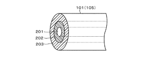
なお、以上の説明では、第1及び第2の光ファイバ101,105の構造について詳しく述べていないが、光ファイバ101,105として、コア部の周りにコア部より屈折率の低い励起高伝播用のクラッドを設けたいわゆるダブルクラッド構造とするのが好ましい。それによれば、より高いレベルの励起光を入射することができるため、より高レベルの出力を得ることができるようになるものである。
In the above description, the structures of the first and second
図2は、第1及び第2の光ファイバ101,105をダブルクラッド構造とした例を示す図である。図に示すように、光ファイバ101,105は、その中央部にコア部201が設けられ、その外側に第1のクラッド202が形成され、さらにその外側に第2のクラッド203が形成されている。第1のクラッド202は、励起光を伝播する機能を有するものであり、光学素子によって集光された光のスポットの外側部分が入射されてこれをそのまま伝播して出力する。この目的のため、第1のクラッド202の屈折率は、コア部201の屈折率より低く設定され、さらに第2のクラッド203の屈折率よりは高くなるように設定されている。
FIG. 2 is a diagram showing an example in which the first and second
このようなダブルクラッド構造の光ファイバを用いることで、励起光を伝播することが可能であるため、大出力の光を生成することができるが、特に第2の光ファイアバ105に適用する際に、そのコア部のカットオフ波長を発振により生成される波長920nm±20nmより短いものとすることで、共振器を簡単にシングルモードで発振させられるようになる。
By using such an optical fiber having a double clad structure, it is possible to propagate pumping light, so that it is possible to generate a large output light. However, particularly when applied to the second
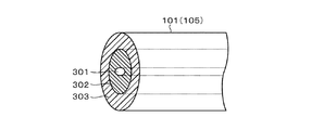
さらに、第1及び第2の光ファイバ101,105は、偏波保持型のファイバであることが望ましい。すなわち、図3に示すように、コア部301が、断面楕円形状に形成されている。このような構成によって、コア部301の短軸方向に偏光を持つ光と長軸方向に偏光を持つ光とで、伝播速度が異なるため、偏波を保持できるようになる。このような光ファイバを用いることによって、不必要な直交成分の少ない、直線偏光を得ることができるものである。なお、図3においても光ファイバ101,105としてはダブルクラッド構造に形成されており、第1のクラッド302と第2のクラッド303を有する。
Furthermore, it is desirable that the first and second
また、図1に示す実施の形態によれば、共振器106において生成される光を挟帯域化するために、回折格子112を用いているが、他の素子を用いて挟帯域化するようにしてもよいものである。
Further, according to the embodiment shown in FIG. 1, the
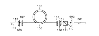
すなわち、回折格子の代わりに、例えば、エタロンを用いることも可能である。図4は、エタロンを用いた共振器106の実施の形態を示す図であり、図中図1と同一構成部分に同じ符号を付す。偏光プリズム111を通過した光116を受けるようにエタロン401が配置され、さらにエタロン401を通過した波長920nm付近の光117を全反射するミラー402が設けられている。
In other words, for example, an etalon can be used instead of the diffraction grating. FIG. 4 is a diagram showing an embodiment of a
全反射ミラー402で反射された光117は、偏光プリズム111、光学素子110及び誘電体ミラー108を介して第2の光ファイバ105に入射され、反対側の誘電体ミラー107で反射されて、誘電体ミラー108、光学素子110及び偏光プリズム111を介して戻り、再び全反射ミラー402で反射される。以上の繰り返しによって発振動作が行なわれる。
The light 117 reflected by the
この実施の形態においは、エタロン401の急峻なフィルタ特性により、FWHM<0.5nmの挟帯域な光を得ることができるものである。
In this embodiment, the narrow band light of FWHM <0.5 nm can be obtained by the steep filter characteristic of the
また、さらに、ファイバ・ブラッグ・グレーティング(FBG)を用いても、同様に挟帯域の光を生成させることができる。図5は、その実施の形態を示す図であり、図1と同一構成部分に同一符号を付す。 Further, even when a fiber Bragg grating (FBG) is used, narrow band light can be generated similarly. FIG. 5 is a diagram showing the embodiment, and the same components as those in FIG.
図5においては、FBGを備えた光ファイバ501と、この光ファイバ501と偏光プリズム111の間に配設された光学素子502を備える。
In FIG. 5, an
偏光プリズム111を通過した光116は、光学素子502で集光され、FBGを備えた光ファイバ501に入射される。光ファイバ501は、FBGによって波長920nm付近の光のうち、FWHM<0.5nmを全反射する機能を有し、それによって波長920nmの挟帯域な光117が光学素子502に導出され、ここでコリメートされて偏光プリズム111に出射され、光学素子110、誘電体ミラー108を介して第2の光ファイバ105に入射される。
The light 116 that has passed through the
入射された光117は誘電体ミラー107で反射されて戻り、結局、波長920nm付近でかつ挟帯域の光を生成する発振動作が行なわれるようになる。
The
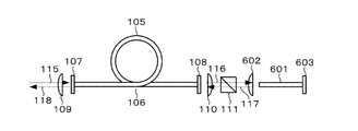
さらに、発振により生成される光を挟帯域化する手段として、励起されていないネオジムイオン(Nd3+)を添加した光ファイバを用いたものも適用できる。図6にその実施の形態を示す。図6において、図1と同一構成部分に同一符号を付す。図6の実施の形態では、ネオジムイオン(Nd3+)が添加された光ファイバ601が設けられると共に、この光ファイバ601と偏光プリズム111の間に光学素子602が設けられ、さらに光ファイバ601の光学素子602とは反対側の端に波長920nm付近の光を全反射するミラー603が設けられている。
Further, as means for narrowing the band of light generated by oscillation, an optical fiber added with unexcited neodymium ions (Nd3 +) can be applied. FIG. 6 shows an embodiment thereof. In FIG. 6, the same components as those in FIG. In the embodiment of FIG. 6, an
偏光プリズム111を通過した光116は、光学素子602で集光されて、光ファイバ601のコア部に入射され、そのままミラー603に到達して反射して戻り、光117として光学素子602、偏光プリズム111、光学素子110を介して第2の光ファイバ105に入射される。この実施の形態においても、誘電体ミラー107とミラー603間で光が反射を繰返す発振動作が行われることになる。
The light 116 that has passed through the
この実施の形態では、図1に示す第1の光ファイバ101で吸収されずに第2の光ファイバ105に入射された波長810nm付近の励起光は、第2の光ファイバ105のコア部のネオジムイオン(Nd3+)を励起するが、誘電体ミラー110によって反射され、誘電体ミラー110から出射されることはない。したがって、光ファイバ601には励起光は入射されることなく、ネオジムイオン(Nd3+)が励起されることはない。
In this embodiment, excitation light having a wavelength of about 810 nm that is incident on the second
共振器106が発振動作を起こすと、その内部で定在波が立つ。このとき、コア部に添加されたネオジムイオン(Nd3+)が励起されている第2の光ファイバ105においては、利得の空間ホールバーニングが生じ、この空間ホールバーニングを埋める多数の縦モードが立つことによって帯域が広がる。しかしながら、光ファイバ601では、添加されたイオンが励起されることがないために、内部で定在波による損失のホールバーニングが生じるため、その他の縦モードにとっては逆位相となって立ちにくくなる。その結果、光ファイバ601を通過して出射される光117は、挟帯域なものとなる。
When the
以上のように、図4〜図6に示す実施の形態においては、共振器106の発振動作で生成される光の帯域を確実に挟帯域にすることが可能である。
As described above, in the embodiment shown in FIGS. 4 to 6, the band of light generated by the oscillation operation of the
なお、図1に示す実施の形態では、半導体レーザ光源113で生成される波長810nm付近の励起光115を、まず第1の光ファイバ101に入射し、第1の光ファイバ101で吸収されなかった励起光115を第2の光ファイバ105入射するように構成したが、先に第2の光ファイバ105に励起光115を入射させ、吸収し切れなかった分を、第1の光ファイバ101に入射するように構成することもできる。
In the embodiment shown in FIG. 1, the
図7は半導体レーザ光源113からの励起光を最初に第2の光ファイバ105に入射させるように構成した実施の形態を示すものである。図7において、図1と同一構成部分に同一符号を付す。図7に示す実施の形態においては、光学素子110と偏光プリズム111の間に、フィルタ114を配設し、半導体レーザ光源113から発生された波長810nmの光115を、このフィルタ114で反射させて光学素子110、誘電体ミラー108を介して第2の光ファイバ105に入射するように構成している。
FIG. 7 shows an embodiment in which the pumping light from the semiconductor
それによって、第2の光ファイバ105のコア部に添加されたネオジムイオン(Nd3+)が励起され、波長920nm±20nmの光を生成するが、ネオジムイオン(Nd3+)で吸収し切れなかった励起光115は、誘電体ミラー107を透過して、光学素子109,104を介して第1の光ファイバ101に入射される。
As a result, neodymium ions (Nd3 +) added to the core of the second
それによって、コア部に添加されたネオジムイオン(Nd3+)が励起され、第1の光ファイバ101は、波長920nm±20nmの光を生成する。
Thereby, neodymium ions (Nd3 +) added to the core portion are excited, and the first
一方第2の光ファイバ105で生成された波長920nm±20nmの光は、誘電体ミラー107で反射されて、第2の光ファイバ105内を通って、誘電体ミラー108に到達し、この誘電体ミラー108を透過して光116として光学素子110、偏光プリズム111を介して回折格子112に導出される。
On the other hand, the light having a wavelength of 920 nm ± 20 nm generated by the second
回折格子112では、入射された光116を光117として返し、それが偏光プリズム111、光学素子110及び誘電体ミラー108を介して再び第2の光ファイバ105に入射される。
In the
以上によって、共振器106が誘電体ミラー107と回折格子112間で光を発振する動作を起こすようになる。回折格子112は、図1で説明したように、発振によって生成される光を挟帯域化する機能を有し、偏光プリズム111は、所定の直線偏波を有する信号に変換する。
As described above, the
共振器106の発振動作で生成された、波長920nm±20nmで挟帯域かつ直線偏波の光118は誘電体ミラー107を透過して光学素子109及び104を介して第1の光ファイバ101に入射され、増幅されて、第1の光ファイバ101から光119として出射され、光学素子103でコリメートされて出力される。
The light 118 having a wavelength of 920 nm ± 20 nm and a linearly polarized wave generated by the oscillation operation of the
この実施の形態によれば、第2の光ファイバ105に、大レベルの励起光を入射することができるので、共振器106の発振動作によって大レベルの光を生成することができるため、第1の光ファイバ101の増幅器としてのゲインをそれほど高くする必要がない。
According to this embodiment, since a large level of excitation light can be incident on the second
この第7図に示す実施の形態においても、発振によって生成される光を挟帯域化するために、図4〜図6に示す実施の形態と同様に、エタロン、FBGを備えた光ファイバ、あるいはコア部にイオンが添加されて励起されていない光ファイバを用いた構成を採用することができるものである。 Also in the embodiment shown in FIG. 7, in order to narrow the band of light generated by oscillation, as in the embodiment shown in FIGS. 4 to 6, an optical fiber equipped with an etalon and FBG, or A configuration using an optical fiber that is not excited by adding ions to the core can be adopted.
さらに、第1図及び第7図で示した実施の形態においては、光ファイバ増幅器を構成する第1の光ファイバと、共振器を構成する第2の光ファイバを光学素子104と109で結合するように構成したが、各光ファイバ101,105の端部を、間に誘電ミラー107と同等の特性を有するミラーを介在させて直設的に接続するように構成したもよいものである。
Further, in the embodiment shown in FIG. 1 and FIG. 7, the first optical fiber constituting the optical fiber amplifier and the second optical fiber constituting the resonator are coupled by the
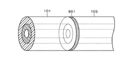
図8は、そのように構成した光ファイバ結合部を示す図であり、第1の光ファイバ101の端部、第2の光ファイバ105の端部のいずれかに、誘電体ミラー801を直接成膜し、さらに他方の光ファイバの端部をその誘電体ミラー801に押し当てて接続するように構成している。
FIG. 8 is a diagram showing an optical fiber coupling portion configured as described above. A
この実施の形態においては、第1の光ファイバ101と第2の光ファイバ105が、直接的に結合されるために、互いに他方の光ファイバへの光の伝播を効率よく実行できるようになるものである。
In this embodiment, since the first
なお、ネオジムイオン(Nd3+)を用いた光ファイバは、波長1.06μmに対して比較的大きな利得を示すようになることから、その波長で発振し易くなる。この波長1.06μmは上位準位が920nm付近の発振と同準位であるため、発振が生ずると効率低下を招く恐れがある。そこで増幅用の第1の光ファイバ101の端面を斜めにカットもしくは研磨することで、ファイバ内部から外部へ出射される光を、ファイバ端面において放射モードで出射させて発振を抑制するように構成することもできるものである。
Note that an optical fiber using neodymium ions (Nd3 +) has a relatively large gain with respect to a wavelength of 1.06 μm, and therefore easily oscillates at that wavelength. This wavelength of 1.06 μm is at the same level as the oscillation near the 920 nm in the upper level. Therefore, if oscillation occurs, the efficiency may be reduced. Therefore, the end face of the first
以上説明したように、図1及び図7で示す光ファイバ増幅装置において、第1の光ファイバ101で増幅されて出力される光119は、挟帯域でかつ直線偏波であるため、第二次高調波を生成させるための基本波として最適なものとなっている。
As described above, in the optical fiber amplifying device shown in FIG. 1 and FIG. 7, the light 119 amplified and output by the first
図9は、図1に示す実施の形態で増幅されて出力された光119を基本波として、その第二次高調波を発生させる装置の一実施の形態を示す図である。図において、図1と同一構成部分に同一符号を付す。 FIG. 9 is a diagram showing an embodiment of an apparatus for generating the second harmonic using the light 119 amplified and outputted in the embodiment shown in FIG. 1 as a fundamental wave. In the figure, the same components as those in FIG.
図9において、フィルタ114を透過した第1の光ファイバ101からの光119を受けるように、光学素子901を介して非線型結晶902が配置され、さらに非線型結晶902を通過した光を受けるように、光学素子903を介してフィルタ904が配置されている。
In FIG. 9, a
非線型結晶902は、入射される波長920nm付近の光119を、その第二次高調波を含む光905に変換する機能を有するもので、例えば周期分極反転構造をした酸化マグネシウムを添加したリチウムナイオベート結晶(PPMgLN)等が適している。
The
光学素子901は、誘電体ミラー114を透過してくる光119を集光して非線型結晶902に入射させる機能を有し、光学素子903は、非線型結晶902から出射された光905をコリメートしてフィルタ904に導出する機能を有する。また、フィルタ904は、光学素子903を介して導出される光905から、第二次高調波906を分離する機能を有し、例えば誘電体ミラーで構成される。すなわち、基本波はそのまま透過し、第二次高調波を反射するものである。
The
非線型結晶902の作用によって、ここを通過する波長920nm±20nmの光119は、波長460nm付近を含む光905となり、この光905は、フィルタ904によって、波長920nm±20nmの基本波905と第二次高調波906に分離される。第二次高調波906は波長460nm付近のいわゆる青色レーザ光である。
By the action of the
図9に示す実施の形態によれば、第1の光ファイバ101から、大レベルに増幅された、波長920nm±20nmで挟帯域かつ直線偏波の光を受けるため、極めて効率よく、第二次高調波を生成して出力することができるようになるものである。
According to the embodiment shown in FIG. 9, since it receives light of a narrow band and linearly polarized light at a wavelength of 920 nm ± 20 nm, which is amplified to a large level, from the first
なお、図9に示す装置においても、光ファイバ101,105としては、図2,3に示す構成のものが適用でき、さらに光ファイバ101と105を結合する手段としても、図8に示すものを適用することが可能である。
In the apparatus shown in FIG. 9 as well, the
以上説明したように、本発明によれば、増幅用の光ファイバと共振器用の光ファイバのいずれかに励起光源からの励起光を入射して励起させ、その光ファイバで吸収されなかった励起光で他方の光ファイバを励起させるように構成し、さらに共振器用の光ファイバによって構成される発振経路中に発振によって生成される光を挟帯域化させるための素子を介在させるように構成したので、励起光を無駄なく使うことができ、さらに挟帯域化素子の損失の影響を抑制することができるため、増幅用の光ファイバから高効率で大出力かつ挟帯域の、第二次高調波を発生させるための基本波に適した光を出射させることができるものである。 As described above, according to the present invention, pumping light from a pumping light source is incident on and pumped into either an optical fiber for amplification or an optical fiber for resonator, and the pumping light that has not been absorbed by the optical fiber. In order to excite the other optical fiber, and further configured to interpose an element for narrowing the light generated by oscillation in the oscillation path constituted by the optical fiber for the resonator, The pump light can be used without waste, and the influence of the loss of the band narrowing element can be suppressed, so that a high-efficiency, large output, narrow band second harmonic is generated from the optical fiber for amplification. It is possible to emit light suitable for the fundamental wave to be generated.
100…光ファイバ増幅装置
101…第1の光ファイバ
102…光ファイバ増幅器
103,104…光学素子
105…第2の光ファイバ
106…共振器
107,108…誘電体ミラー
109,110…光学素子
111…偏光プリズム
112…回折格子
113…半導体レーザ光源
114…フィルタ
401…エタロン
501…FBGを備えた光ファイバ
601…励起されない光ファイバ
902…非線型結晶
DESCRIPTION OF SYMBOLS 100 ...
Claims (6)
コア部にネオジムイオン(Nd3+)が添加され、当該コア部に励起光が入射されることで前記第1の光と同等の波長でかつ第1の光より狭帯域の第2の光を共振により生成する共振器として構成される第2の光ファイバを有した共振器と、
励起光源と、
前記光ファイバ増幅器と前記共振器を光学的に結合すると共に、前記励起光源からの励起光を前記第1の光ファイバまたは第2の光ファイバのいずれかに入射し、当該入射した励起光のうち前記ネオジムイオン(Nd3+)で吸収されなかった励起光を他方の光ファイバへ前記励起光として入射し、さらに前記共振器で生成された前記第2の光を前記第1の光ファイバに入射させる光学手段と、
を具備したことを特徴とする光ファイバ増幅装置。 An optical fiber amplifier having a first optical fiber that outputs a first light having a wavelength of 920 nm ± 20 nm when neodymium ions (Nd3 +) are added to the core part and excitation light is incident on the core part;
Neodymium ions (Nd3 +) are added to the core portion, and excitation light is incident on the core portion, so that the second light having the same wavelength as the first light and a narrower band than the first light is resonated. A resonator having a second optical fiber configured as a resonator to generate;
An excitation light source;
The optical fiber amplifier and the resonator are optically coupled, and the pumping light from the pumping light source is incident on either the first optical fiber or the second optical fiber. An optical system in which excitation light that has not been absorbed by the neodymium ions (Nd3 +) is incident on the other optical fiber as the excitation light, and the second light generated by the resonator is incident on the first optical fiber. Means,
An optical fiber amplifying apparatus comprising:
コア部にネオジムイオン(Nd3+)が添加され、当該コア部に励起光が入射されることで前記第1の光と同等の波長でかつ第1の光より狭帯域の第2の光を共振により生成する共振器として構成される第2の光ファイバを有した共振器と、
励起光源と、
前記光ファイバ増幅手段と前記共振器を光学的に結合すると共に、前記励起光源からの励起光を前記第1の光ファイバまたは第2の光ファイバのいずれかに入射し、当該入射した励起光のうち前記ネオジムイオン(Nd3+)で吸収されなかった励起光を他方の光ファイバへ前記励起光として入射し、さらに前記共振手段で生成された前記第2の光を前記第1の光ファイバに入射させる第1の光学手段と、
前記光ファイバ増幅器で増幅された前記第1の光を非線型素子を通過させることで、波長460nm±10nmの第3の光を生成して出力する第2の光学手段と、
を具備したことを特徴とする第二次高調波発生装置。 An optical fiber amplifier having a first optical fiber that outputs a first light having a wavelength of 920 nm ± 20 nm when neodymium ions (Nd3 +) are added to the core part and excitation light is incident on the core part;
Neodymium ions (Nd3 +) are added to the core portion, and excitation light is incident on the core portion, so that the second light having the same wavelength as the first light and narrower than the first light is resonated. A resonator having a second optical fiber configured as a resonator to generate;
An excitation light source;
The optical fiber amplifying means and the resonator are optically coupled, and the pumping light from the pumping light source is incident on either the first optical fiber or the second optical fiber. Among them, the excitation light that has not been absorbed by the neodymium ions (Nd3 +) is incident on the other optical fiber as the excitation light, and the second light generated by the resonance means is incident on the first optical fiber. First optical means;
Second optical means for generating and outputting third light having a wavelength of 460 nm ± 10 nm by passing the first light amplified by the optical fiber amplifier through a nonlinear element;
A second-order harmonic generator characterized by comprising:
前記励起光が入射された光ファイバで吸収されなかった励起光を他方の光ファイバに励起光として入射するステップと、
前記共振器で生成された前記第2の光を前記光ファイバ増幅器で増幅して出力するステップと、
を具備したことを特徴とする光生成方法。 An optical fiber amplifier having a first optical fiber that outputs a first light having a wavelength of 920 nm ± 20 nm when neodymium ions (Nd3 +) are added to the core part and excitation light is incident on the core part, and a core The second light that is generated by resonance by adding a neodymium ion (Nd3 +) to the portion and the excitation light is incident on the core portion to generate second light having a wavelength equivalent to that of the first light and a narrow band. Optically coupling a resonator having a fiber, and injecting excitation light into one of the first optical fiber and the second optical fiber, and exciting the excitation light;
Entering the pumping light that has not been absorbed by the optical fiber into which the pumping light is incident into the other optical fiber; and
Amplifying and outputting the second light generated by the resonator by the optical fiber amplifier;
A light generation method comprising:
前記励起光が入射された光ファイバで吸収されなかった励起光を他方の光ファイバに励起光として入射するステップと、
前記共振器で生成された前記第2の光を前記光ファイバ増幅器で増幅して出力するステップと、
光ファイバ増幅器から出力された光を非線型素子を通して、前記光ファイバ増幅器から出力された光の第二次高調波を得るステップと、
を具備したことを特徴とする第二次高調波生成方法。 An optical fiber amplifier having a first optical fiber that outputs a first light having a wavelength of 920 nm ± 20 nm when neodymium ions (Nd3 +) are added to the core part and excitation light is incident on the core part, and a core The second light that is generated by resonance by adding a neodymium ion (Nd3 +) to the portion and the excitation light is incident on the core portion to generate second light having a wavelength equivalent to that of the first light and a narrow band. Optically coupling a resonator having a fiber, and injecting excitation light into one of the first optical fiber and the second optical fiber, and exciting the excitation light;
Entering the pumping light that has not been absorbed by the optical fiber into which the pumping light is incident into the other optical fiber; and
Amplifying and outputting the second light generated by the resonator by the optical fiber amplifier;
Obtaining the second harmonic of the light output from the optical fiber amplifier through the nonlinear element through the light output from the optical fiber amplifier;
A second-order harmonic generation method comprising:
Priority Applications (1)
| Application Number | Priority Date | Filing Date | Title |
|---|---|---|---|
| JP2004108089A JP2005294570A (en) | 2004-03-31 | 2004-03-31 | Optical fiber amplifier, second harmonic generation device, light generation method, and second harmonic generation method |
Applications Claiming Priority (1)
| Application Number | Priority Date | Filing Date | Title |
|---|---|---|---|
| JP2004108089A JP2005294570A (en) | 2004-03-31 | 2004-03-31 | Optical fiber amplifier, second harmonic generation device, light generation method, and second harmonic generation method |
Publications (1)
| Publication Number | Publication Date |
|---|---|
| JP2005294570A true JP2005294570A (en) | 2005-10-20 |
Family
ID=35327157
Family Applications (1)
| Application Number | Title | Priority Date | Filing Date |
|---|---|---|---|
| JP2004108089A Pending JP2005294570A (en) | 2004-03-31 | 2004-03-31 | Optical fiber amplifier, second harmonic generation device, light generation method, and second harmonic generation method |
Country Status (1)
| Country | Link |
|---|---|
| JP (1) | JP2005294570A (en) |
Cited By (4)
| Publication number | Priority date | Publication date | Assignee | Title |
|---|---|---|---|---|
| WO2007066641A1 (en) * | 2005-12-05 | 2007-06-14 | Matsushita Electric Industrial Co., Ltd. | Laser light source and image display |
| WO2007083452A1 (en) * | 2006-01-23 | 2007-07-26 | Matsushita Electric Industrial Co., Ltd. | Laser light source device, image display and illuminator |
| JP2008026873A (en) * | 2006-06-23 | 2008-02-07 | Matsushita Electric Ind Co Ltd | Wavelength conversion device and two-dimensional image display device |
| JP2009537979A (en) * | 2006-05-17 | 2009-10-29 | エオリト システム | High-power optical fiber pulse laser equipment |
-
2004
- 2004-03-31 JP JP2004108089A patent/JP2005294570A/en active Pending
Cited By (8)
| Publication number | Priority date | Publication date | Assignee | Title |
|---|---|---|---|---|
| WO2007066641A1 (en) * | 2005-12-05 | 2007-06-14 | Matsushita Electric Industrial Co., Ltd. | Laser light source and image display |
| US7675950B2 (en) | 2005-12-05 | 2010-03-09 | Panasonic Corporation | Laser light source device and image display apparatus |
| JP5156385B2 (en) * | 2005-12-05 | 2013-03-06 | パナソニック株式会社 | Laser light source device and image display device |
| WO2007083452A1 (en) * | 2006-01-23 | 2007-07-26 | Matsushita Electric Industrial Co., Ltd. | Laser light source device, image display and illuminator |
| US7965916B2 (en) | 2006-01-23 | 2011-06-21 | Panasonic Corporation | Laser light source device, image display and illuminator |
| JP5096171B2 (en) * | 2006-01-23 | 2012-12-12 | パナソニック株式会社 | Laser light source device, image display device, and illumination device |
| JP2009537979A (en) * | 2006-05-17 | 2009-10-29 | エオリト システム | High-power optical fiber pulse laser equipment |
| JP2008026873A (en) * | 2006-06-23 | 2008-02-07 | Matsushita Electric Ind Co Ltd | Wavelength conversion device and two-dimensional image display device |
Similar Documents
| Publication | Publication Date | Title |
|---|---|---|
| CN102388512B (en) | Cascaded Raman fiber laser system based on filter fiber | |
| JP2011023532A (en) | Optical amplifier, laser device, and light source device | |
| CN105428976A (en) | Mode-locked fiber laser and pulse laser generation method | |
| JP5512348B2 (en) | Optical fiber for amplification with optical components, and fiber laser device using the same | |
| WO2003067723A1 (en) | Multimode optical fiber, fiber laser amplifier, and fiber laser oscillator | |
| JP3331726B2 (en) | Optical fiber laser device | |
| JP6807699B2 (en) | Laser device | |
| JP2010028053A (en) | Fiber laser device, laser beam machine, and laser beam machining method | |
| JP3905479B2 (en) | Fiber laser equipment | |
| JP2005203430A (en) | Optical fiber laser and laser beam generating method using the same | |
| JP2014225584A (en) | Fiber laser device | |
| US20050036531A1 (en) | Laser device | |
| JP2005294570A (en) | Optical fiber amplifier, second harmonic generation device, light generation method, and second harmonic generation method | |
| JPH1187824A (en) | Optical amplifier | |
| JP5390907B2 (en) | Cascade Raman resonator and optical fiber laser | |
| JPH04501787A (en) | laser system | |
| JPH09148660A (en) | Semiconductor laser device and optical amplifier | |
| CN114725762B (en) | Middle infrared saturable absorber and all-fiber middle infrared pulse laser | |
| JP2003031879A (en) | Optical device, optical fiber used therefor, pulse generator, optical amplifier, and fiber laser | |
| CN114976833B (en) | A thulium-doped Raman hybrid gain fiber laser | |
| JP2004287105A (en) | Optical switch and fiber laser using optical switch | |
| JP2016180844A (en) | Fiber laser device | |
| JP3230458B2 (en) | Optical amplifier | |
| EP1030416A2 (en) | Laser amplifier and laser oscillator | |
| TW200924329A (en) | Passive type all-optical-fiber Q-switched laser |