JP2005294461A - Method for manufacturing coil charge green molded body - Google Patents
Method for manufacturing coil charge green molded body Download PDFInfo
- Publication number
- JP2005294461A JP2005294461A JP2004106181A JP2004106181A JP2005294461A JP 2005294461 A JP2005294461 A JP 2005294461A JP 2004106181 A JP2004106181 A JP 2004106181A JP 2004106181 A JP2004106181 A JP 2004106181A JP 2005294461 A JP2005294461 A JP 2005294461A
- Authority
- JP
- Japan
- Prior art keywords
- coil
- spiral
- core
- powder
- manufacturing
- Prior art date
- Legal status (The legal status is an assumption and is not a legal conclusion. Google has not performed a legal analysis and makes no representation as to the accuracy of the status listed.)
- Granted
Links
- 238000000034 method Methods 0.000 title claims abstract description 53
- 238000004519 manufacturing process Methods 0.000 title claims abstract description 50
- 239000000843 powder Substances 0.000 claims abstract description 82
- 229910052751 metal Inorganic materials 0.000 claims abstract description 32
- 239000002184 metal Substances 0.000 claims abstract description 32
- 238000000748 compression moulding Methods 0.000 claims abstract description 9
- 230000008569 process Effects 0.000 claims description 38
- 238000005452 bending Methods 0.000 claims description 9
- 238000000465 moulding Methods 0.000 abstract description 10
- 238000010586 diagram Methods 0.000 description 11
- 229910045601 alloy Inorganic materials 0.000 description 10
- 239000000956 alloy Substances 0.000 description 10
- 238000007906 compression Methods 0.000 description 10
- 239000011810 insulating material Substances 0.000 description 10
- 230000006835 compression Effects 0.000 description 9
- 239000000428 dust Substances 0.000 description 6
- XEEYBQQBJWHFJM-UHFFFAOYSA-N iron Substances [Fe] XEEYBQQBJWHFJM-UHFFFAOYSA-N 0.000 description 6
- 238000010438 heat treatment Methods 0.000 description 5
- 239000000314 lubricant Substances 0.000 description 5
- 239000000463 material Substances 0.000 description 5
- 229910052802 copper Inorganic materials 0.000 description 4
- 229910052737 gold Inorganic materials 0.000 description 4
- 238000003825 pressing Methods 0.000 description 4
- 229910052742 iron Inorganic materials 0.000 description 3
- 239000000203 mixture Substances 0.000 description 3
- 230000004048 modification Effects 0.000 description 3
- 238000012986 modification Methods 0.000 description 3
- 229910017061 Fe Co Inorganic materials 0.000 description 2
- 229910017082 Fe-Si Inorganic materials 0.000 description 2
- 229910017133 Fe—Si Inorganic materials 0.000 description 2
- 229910001030 Iron–nickel alloy Inorganic materials 0.000 description 2
- 229910001096 P alloy Inorganic materials 0.000 description 2
- 230000001747 exhibiting effect Effects 0.000 description 2
- 230000004907 flux Effects 0.000 description 2
- HQKMJHAJHXVSDF-UHFFFAOYSA-L magnesium stearate Chemical compound [Mg+2].CCCCCCCCCCCCCCCCCC([O-])=O.CCCCCCCCCCCCCCCCCC([O-])=O HQKMJHAJHXVSDF-UHFFFAOYSA-L 0.000 description 2
- 230000005389 magnetism Effects 0.000 description 2
- 229910052759 nickel Inorganic materials 0.000 description 2
- 238000012856 packing Methods 0.000 description 2
- 229910000889 permalloy Inorganic materials 0.000 description 2
- 238000009702 powder compression Methods 0.000 description 2
- 239000011347 resin Substances 0.000 description 2
- 229920005989 resin Polymers 0.000 description 2
- 229910000702 sendust Inorganic materials 0.000 description 2
- 229910052710 silicon Inorganic materials 0.000 description 2
- 229910052723 transition metal Inorganic materials 0.000 description 2
- 150000003624 transition metals Chemical class 0.000 description 2
- 239000004925 Acrylic resin Substances 0.000 description 1
- 229920000178 Acrylic resin Polymers 0.000 description 1
- 229910000976 Electrical steel Inorganic materials 0.000 description 1
- 229910000676 Si alloy Inorganic materials 0.000 description 1
- XUIMIQQOPSSXEZ-UHFFFAOYSA-N Silicon Chemical compound [Si] XUIMIQQOPSSXEZ-UHFFFAOYSA-N 0.000 description 1
- 229910000831 Steel Inorganic materials 0.000 description 1
- 230000002411 adverse Effects 0.000 description 1
- 229910052782 aluminium Inorganic materials 0.000 description 1
- CEGOLXSVJUTHNZ-UHFFFAOYSA-K aluminium tristearate Chemical compound [Al+3].CCCCCCCCCCCCCCCCCC([O-])=O.CCCCCCCCCCCCCCCCCC([O-])=O.CCCCCCCCCCCCCCCCCC([O-])=O CEGOLXSVJUTHNZ-UHFFFAOYSA-K 0.000 description 1
- 229940063655 aluminum stearate Drugs 0.000 description 1
- 238000000889 atomisation Methods 0.000 description 1
- AGXUVMPSUKZYDT-UHFFFAOYSA-L barium(2+);octadecanoate Chemical compound [Ba+2].CCCCCCCCCCCCCCCCCC([O-])=O.CCCCCCCCCCCCCCCCCC([O-])=O AGXUVMPSUKZYDT-UHFFFAOYSA-L 0.000 description 1
- 239000011230 binding agent Substances 0.000 description 1
- 229910052791 calcium Inorganic materials 0.000 description 1
- 239000011575 calcium Substances 0.000 description 1
- CJZGTCYPCWQAJB-UHFFFAOYSA-L calcium stearate Chemical compound [Ca+2].CCCCCCCCCCCCCCCCCC([O-])=O.CCCCCCCCCCCCCCCCCC([O-])=O CJZGTCYPCWQAJB-UHFFFAOYSA-L 0.000 description 1
- 239000008116 calcium stearate Substances 0.000 description 1
- 235000013539 calcium stearate Nutrition 0.000 description 1
- 229910052804 chromium Inorganic materials 0.000 description 1
- 238000005868 electrolysis reaction Methods 0.000 description 1
- 239000003822 epoxy resin Substances 0.000 description 1
- 238000009415 formwork Methods 0.000 description 1
- 238000009689 gas atomisation Methods 0.000 description 1
- 229910052749 magnesium Inorganic materials 0.000 description 1
- 239000011777 magnesium Substances 0.000 description 1
- 235000019359 magnesium stearate Nutrition 0.000 description 1
- 239000003921 oil Substances 0.000 description 1
- 239000011368 organic material Substances 0.000 description 1
- 239000002245 particle Substances 0.000 description 1
- 229920006122 polyamide resin Polymers 0.000 description 1
- 229920000647 polyepoxide Polymers 0.000 description 1
- 229920001721 polyimide Polymers 0.000 description 1
- 239000009719 polyimide resin Substances 0.000 description 1
- 238000005096 rolling process Methods 0.000 description 1
- 239000010703 silicon Substances 0.000 description 1
- 239000010959 steel Substances 0.000 description 1
- FRKHZXHEZFADLA-UHFFFAOYSA-L strontium;octadecanoate Chemical compound [Sr+2].CCCCCCCCCCCCCCCCCC([O-])=O.CCCCCCCCCCCCCCCCCC([O-])=O FRKHZXHEZFADLA-UHFFFAOYSA-L 0.000 description 1
- 229920001187 thermosetting polymer Polymers 0.000 description 1
- 238000009692 water atomization Methods 0.000 description 1
- 229910052725 zinc Inorganic materials 0.000 description 1
- 239000011701 zinc Substances 0.000 description 1
- XOOUIPVCVHRTMJ-UHFFFAOYSA-L zinc stearate Chemical compound [Zn+2].CCCCCCCCCCCCCCCCCC([O-])=O.CCCCCCCCCCCCCCCCCC([O-])=O XOOUIPVCVHRTMJ-UHFFFAOYSA-L 0.000 description 1
Images


Classifications
-
- H—ELECTRICITY
- H01—ELECTRIC ELEMENTS
- H01F—MAGNETS; INDUCTANCES; TRANSFORMERS; SELECTION OF MATERIALS FOR THEIR MAGNETIC PROPERTIES
- H01F41/00—Apparatus or processes specially adapted for manufacturing or assembling magnets, inductances or transformers; Apparatus or processes specially adapted for manufacturing materials characterised by their magnetic properties
- H01F41/02—Apparatus or processes specially adapted for manufacturing or assembling magnets, inductances or transformers; Apparatus or processes specially adapted for manufacturing materials characterised by their magnetic properties for manufacturing cores, coils, or magnets
- H01F41/0206—Manufacturing of magnetic cores by mechanical means
- H01F41/0246—Manufacturing of magnetic circuits by moulding or by pressing powder
-
- H—ELECTRICITY
- H01—ELECTRIC ELEMENTS
- H01F—MAGNETS; INDUCTANCES; TRANSFORMERS; SELECTION OF MATERIALS FOR THEIR MAGNETIC PROPERTIES
- H01F27/00—Details of transformers or inductances, in general
- H01F27/24—Magnetic cores
- H01F27/255—Magnetic cores made from particles
-
- H—ELECTRICITY
- H01—ELECTRIC ELEMENTS
- H01F—MAGNETS; INDUCTANCES; TRANSFORMERS; SELECTION OF MATERIALS FOR THEIR MAGNETIC PROPERTIES
- H01F3/00—Cores, Yokes, or armatures
- H01F3/08—Cores, Yokes, or armatures made from powder
-
- H—ELECTRICITY
- H01—ELECTRIC ELEMENTS
- H01F—MAGNETS; INDUCTANCES; TRANSFORMERS; SELECTION OF MATERIALS FOR THEIR MAGNETIC PROPERTIES
- H01F41/00—Apparatus or processes specially adapted for manufacturing or assembling magnets, inductances or transformers; Apparatus or processes specially adapted for manufacturing materials characterised by their magnetic properties
- H01F41/02—Apparatus or processes specially adapted for manufacturing or assembling magnets, inductances or transformers; Apparatus or processes specially adapted for manufacturing materials characterised by their magnetic properties for manufacturing cores, coils, or magnets
- H01F41/04—Apparatus or processes specially adapted for manufacturing or assembling magnets, inductances or transformers; Apparatus or processes specially adapted for manufacturing materials characterised by their magnetic properties for manufacturing cores, coils, or magnets for manufacturing coils
-
- H—ELECTRICITY
- H01—ELECTRIC ELEMENTS
- H01F—MAGNETS; INDUCTANCES; TRANSFORMERS; SELECTION OF MATERIALS FOR THEIR MAGNETIC PROPERTIES
- H01F5/00—Coils
Landscapes
- Engineering & Computer Science (AREA)
- Power Engineering (AREA)
- Manufacturing & Machinery (AREA)
- Coils Or Transformers For Communication (AREA)
- Powder Metallurgy (AREA)
- Manufacturing Cores, Coils, And Magnets (AREA)
Abstract
Description
本発明は電子部品として用いられるコイル封入圧粉成型体の製造方法に係り、特に、コイル端子が表面に露出している表面実装に適した圧粉成型体を、少ない工程数および低廉な製造コストで製造でき、製造歩留まりを向上させることが可能なコイル封入型圧粉成型体の製造方法に関する。 The present invention relates to a method for manufacturing a coil-embedded compact used as an electronic component, and in particular, a compact molded body suitable for surface mounting with coil terminals exposed on the surface, with a small number of steps and low manufacturing costs. It is related with the manufacturing method of the coil inclusion type compacting body which can be manufactured by this and can improve a manufacture yield.
近年の電子機器の小型化に伴って電子部品の小型化が要求されているが、小型化されたインダクタなどの電子部品として、コイルが磁性金属粉末の内部に封入された状態で成型されたコイル封入圧粉成型体が用いられている。 With the recent miniaturization of electronic equipment, miniaturization of electronic components is required, but as an electronic component such as a miniaturized inductor, a coil molded in a state where the coil is enclosed in magnetic metal powder An encapsulated green compact is used.
このようなコイル封入圧粉成型体では、磁性金属粉末を成型して形成された2つのコアの間にコイルを挟んで接合し、これによってコイルが2つの前記コアの内部に密封された構造となっている。しかし、2つのコアを接合したものでは、2つのコア間に空隙が生じ易いため、コイルとコアとの間には隙間ができ易い。このように、コイルとコアとの間に隙間ができることは、インダクタンスの低下を招くことから好ましくない。 In such a coil-enclosed compact, a coil is sandwiched and joined between two cores formed by molding magnetic metal powder, and the coil is sealed inside the two cores. It has become. However, in the case where two cores are joined, a gap is easily generated between the two cores, so that a gap is easily formed between the coil and the core. Thus, it is not preferable that a gap is formed between the coil and the core because inductance is reduced.
以下に示す特許文献1の図1には、コイルとコアとの間の隙間を無くすことができるコイル封入圧粉成型体の製造方法が開示されている。
FIG. 1 of
この特許文献1の図1に記載されたコイル封入圧粉成型体の製造方法では、まず、下型枠と上型枠とから構成される型枠(ダイ)の下型枠内部に絶縁材をコーティングした磁性金属粉末を充填した後、この磁性金属粉末の下方および上方から、下パンチおよび上パンチを用いて圧縮成型して下部コアを成型する。
In the method of manufacturing a coil-filled green compact described in FIG. 1 of
次に、前記下型枠内に形成された下部コアの上にコイルを載置する。このとき、前記コイルの端部に形成された端子を下部コアの側方から外側に向かって直線状に延ばした状態で、下型枠と上型枠との間に挟む。そして、下部コアの上に載置したコイルが埋まるように、磁性金属粉末を下型枠から上型枠にかけて再充填し、下部コアおよび再充填した磁性金属粉末を上下方向から下パンチおよび上パンチによって圧縮して上部コアを成型すると、下部コアと上部コアとが一体となったコイル封入圧粉成型体が製造される。 Next, a coil is placed on the lower core formed in the lower mold. At this time, the terminal formed at the end of the coil is sandwiched between the lower mold frame and the upper mold frame in a state of extending linearly from the side of the lower core toward the outside. Then, the magnetic metal powder is refilled from the lower mold frame to the upper mold frame so that the coil placed on the lower core is buried, and the lower core and the refilled magnetic metal powder are vertically punched from the lower punch and the upper punch. When the upper core is molded by compression, a coil-enclosed powder compact in which the lower core and the upper core are integrated is manufactured.
この特許文献1に記載された製造方法によって製造されたコイル封入圧粉成型体では、成型された下部コア上にコイルを載置した後、このコイルを埋めるように磁性金属粉末を再充填しているため、製造されたコイル封入圧粉成型体は、下部コアおよび上部コアと、コイルとの間に隙間が形成されずに、インダクタンスを大きくすることができる。
しかし、前記特許文献1に開示された製造方法では、下部コアを圧縮成型してコイルを下部コア上に載置した後、さらに再充填した磁性金属粉末を圧縮して上部コアを成型しているため、2度の圧縮工程を必要としているため、工程数が多くなる。
However, in the manufacturing method disclosed in
また、コイルの端子を下型枠と上型枠との間に挟みこんだ状態で下部コアおよび上部コアを成型するため、型枠(ダイ)を下型枠と上型枠とに2分割された構造とする必要があるため、(型枠)ダイの製造コストが大きくなる。 Further, in order to mold the lower core and the upper core with the coil terminals sandwiched between the lower mold frame and the upper mold frame, the mold (die) is divided into two parts, the lower mold frame and the upper mold frame. Therefore, the manufacturing cost of the (formwork) die increases.
また、下パンチと上パンチによって、下部コアを圧縮成型する際や上部コアを圧縮成型する際に、下パンチと上パンチの圧縮動作によってコイルが上下方向に移動するが、このとき、コイルの端子が下型枠と上型枠との間に挟まれた状態であることから、コイルの上下移動に合わせて下型枠と上型枠とを移動させなければコイルの端子が曲がってしまう。前記特許文献1に開示された製造方法では、コイルの端子の曲がりを回避するために、下型枠と上型枠とで構成された型枠(ダイ)をコイルの上下移動に合わせて移動させる必要がある。また、ダイが充填位置にあるときに、上パンチを2回上下運動しなければならない。これらの動作を行うためには、油圧式の圧縮成型機を設ける必要があるため、設備が複雑になるとともに、設備費用も大きくなる。
In addition, when the lower core and the upper punch are compression-molded by the lower punch and the upper punch, the coil moves in the vertical direction by the compression operation of the lower punch and the upper punch. Is sandwiched between the lower mold frame and the upper mold frame, the terminal of the coil is bent unless the lower mold frame and the upper mold frame are moved in accordance with the vertical movement of the coil. In the manufacturing method disclosed in
さらに、前記特許文献1に記載された製造方法によって製造されたコイル封入圧粉成型体では、コイルの端子が下部コアおよび上部コアの側方から外側に向かって直線状に延びた構造となっているため、小型化や表面実装に使用するには適した構造ではない。このコイル封入圧粉成型体を表面実装に適した形状とするには、コイル端子をコイル封入圧粉成型体の側面に沿って曲げる工程が必要となってしまい、その分の工程数が多くなってしまう。また、この端子を曲げる工程の際に、下部コアや上部コアが割れてしまい、製造歩留まりが低下するといった問題もある。
Furthermore, in the coil-filled green compact produced by the production method described in
本発明は前記従来の課題を解決するものであり、工程数が少なく、製造コストの低廉を図ることができ、製造歩留まりを向上させることが可能なコイル封入圧粉成型体の製造方法を提供することを目的とする。 The present invention solves the above-mentioned conventional problems, and provides a method for producing a coil-enclosed compact that can reduce the number of steps, reduce the production cost, and improve the production yield. For the purpose.
本発明のコイル封入圧粉成型体の製造方法は、以下の工程を有することを特徴とするものである。
(a)螺旋部と、前記螺旋部から側部方向に向かって延びる脚部とを有する螺旋構造体の前記脚部を前記螺旋部の下方に屈曲させて、第1の端子部と螺旋部とを有するコイルを形成する工程と、
(b)前記コイルを成型型内に載置し、このとき前記コイルの前記第1の端子部の外側面を、前記成型型内の内側面に当接させる工程と、
(c)前記成型型内に磁性金属粉末を充填し、前記コイルを前記磁性金属粉末で埋める工程と、
(d)前記金属粉末を圧縮成型する工程。
The method for producing a coil-embedded compact of the present invention has the following steps.
(A) The first terminal portion and the spiral portion are formed by bending the leg portion of the spiral structure having a spiral portion and a leg portion extending in the lateral direction from the spiral portion. Forming a coil having:
(B) placing the coil in a mold, and contacting the outer surface of the first terminal portion of the coil with the inner surface of the mold;
(C) filling the mold with magnetic metal powder and filling the coil with the magnetic metal powder;
(D) A step of compression molding the metal powder.
この場合、前記(a)工程で、前記脚部の先端領域を、前記螺旋部方向に向かって屈曲させ、第2の端子部を形成するものとして構成することができる。 In this case, in the step (a), the tip region of the leg portion can be bent toward the spiral portion direction to form the second terminal portion.
また、前記(a)工程で、前記第1の端子部を、前記螺旋部を基準として反対方向に位置するように形成し、前記(b)工程で、前記第1の端子部の外側面を、前記コイルの螺旋部を基準として互いに対向する方向に位置する前記内側面に当接させることや、前記(a)工程で、前記第1の端子部を、前記螺旋部を基準として同じ方向に位置するように形成し、前記(b)工程で、前記第1の端子部の外側面を、前記コイルの螺旋部を基準として同じ方向に位置する前記内側面に当接させることとしても良い。 Further, in the step (a), the first terminal portion is formed to be positioned in the opposite direction with respect to the spiral portion, and in the step (b), the outer surface of the first terminal portion is formed. Abutting against the inner surfaces located in opposite directions with respect to the spiral portion of the coil, or in the step (a), the first terminal portion is placed in the same direction with respect to the spiral portion. In the step (b), the outer surface of the first terminal portion may be brought into contact with the inner surface located in the same direction with reference to the spiral portion of the coil.
本発明のコイル封入圧粉成型体の製造方法では、コイルの周囲に粉体を充填した後、この粉体の圧縮工程を1度行うだけで、コアを圧縮成型できるため、工程数を少なくでき、容易に製造することができる。 In the method of manufacturing a coil-enclosed compact of the present invention, the core can be compression-molded by filling the powder around the coil and then performing this powder compression process only once, so the number of steps can be reduced. Can be manufactured easily.
また、コイルの端子部の側面は、前記ダイに形成された穴部の内側面に当接した状態で粉体の充填が行われるため、粉体が前記端子部の側面とダイの穴部の内側面との間に充填されることはない。そのため、コアの側面に、前記端子部の側面を露出させることが可能となるため、表面実装に適したコイル封入圧粉成型体を容易に製造できる。 In addition, since the powder filling is performed with the side surface of the terminal portion of the coil in contact with the inner surface of the hole portion formed in the die, the powder is formed between the side surface of the terminal portion and the hole portion of the die. There is no filling between the inner surface. Therefore, it is possible to expose the side surface of the terminal portion on the side surface of the core, and thus it is possible to easily manufacture a coil-enclosed powder compact suitable for surface mounting.
また、コイルにあらかじめ端子を形成しているため、コイル全体をダイの穴部内に載置することができる。そのため、ダイを下型枠と上型枠とに2分割した構造とする必要がなく、一体的な構造とすることができるため、ダイの製造コストを低廉にすることが可能となる。 Moreover, since the terminal is previously formed in the coil, the whole coil can be mounted in the hole part of die | dye. Therefore, it is not necessary to divide the die into a lower mold frame and an upper mold frame, and an integrated structure can be obtained, so that the die manufacturing cost can be reduced.
また、コアを成型するための粉体の圧縮成型工程時に、前記ダイの穴部内にコイル全体を載置できるので、コイルが上下方向に移動しても、コイルの上下移動に合わせてダイを移動させ必要がないため、ダイの上下移動のためにの油圧装置などのダイ駆動手段を設ける必要がなく、設備を簡単な構造とすることができるとともに、設備費用も低廉にすることが可能となる。 In addition, the entire coil can be placed in the hole of the die during the powder compression molding process to mold the core, so that even if the coil moves in the vertical direction, the die moves according to the vertical movement of the coil. Therefore, it is not necessary to provide a die drive means such as a hydraulic device for moving the die up and down, and the equipment can be made a simple structure and the equipment cost can be reduced. .
さらに、コイルにあらかじめ端子を形成しているため、コイル全体をダイの穴部内に載置できるため、表面実装に適した構造のコイル封入圧粉成型体を容易に製造できる。また、コアが形成されていないときに、コイル単体の状態時に端子を形成しているため、端子を曲げる工程の際に、コアが割れてしまい、製造歩留まりが低下するといった問題は発生しないため、製造歩留まりの向上を図ることができる。 Furthermore, since the terminal is formed in advance in the coil, the entire coil can be placed in the hole of the die, and therefore a coil-enclosed powder compact having a structure suitable for surface mounting can be easily manufactured. In addition, when the core is not formed, since the terminal is formed in the state of the coil alone, the problem that the core is broken during the process of bending the terminal and the manufacturing yield is reduced does not occur. The production yield can be improved.
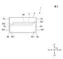
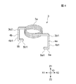
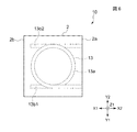
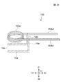
図1は、本発明の製造方法によって製造されたコイル封入圧粉成型体の第1の例を上面から見た平面図、図2は図1に示すコイル封入圧粉成型体を正面方向(図1に示すY1方向)から見た正面図、図3は図1に示すコイル封入圧粉成型体を右側面方向(図1に示すX2方向)から見た側面図、図4は図1に示すコイル封入圧粉成型体の内部に封入されたコイルを示す斜視図である。 FIG. 1 is a plan view of a first example of a coil-embedded compact formed by the manufacturing method of the present invention as viewed from above, and FIG. 2 is a front view of the coil-embedded compact shown in FIG. 3 is a front view as seen from the Y1 direction shown in FIG. 1, FIG. 3 is a side view of the coil-filled green compact shown in FIG. 1 as seen from the right side direction (X2 direction as shown in FIG. 1), and FIG. It is a perspective view which shows the coil enclosed inside the coil enclosure compacting body.
図1ないし図3に示すコイル封入圧粉成型体1は、磁芯を一体化したインダクタなどの電子部品として使用されるものである。
A coil-enclosed
前記コイル封入圧粉成型体1は、立方体に形成されたコア2と、このコア2の内部に封入されたコイル3とで構成されている。
The coil-enclosed powder compact 1 is composed of a
前記コア2は、磁性金属粉末を含有した粉末集合体71を圧縮して成型した圧縮成型体である。この磁性金属粉末は、軟磁性を示す遷移金属や、Fe、CoおよびNiから選択される1種以上を含む合金、例えばパーマロイ(Fe−Ni合金)、センダスト(Fe−Si−Al合金)、ケイ素鋼(Fe−Si合金)、Fe−Co合金、Fe−P合金などの合金を使用することができる。
The
前記コア2は前記コイル3の表面を隙間なく埋めるように充填された状態でコイル3を密封しており、前記コア2と前記コイル3との間に隙間がない。そのため、前記コイル封入圧粉成型体1ではインダクタンスを高くすることが可能となっている。
The
図1に示す実施形態では、前記コア2の平面形状における縦寸法L1と横寸法L2とは同じ寸法で形成されているが、本発明ではこれに限定されるものではなく、前記縦寸法L1と横寸法L2とが異なる寸法として構成しても良い。
In the embodiment shown in FIG. 1, the vertical dimension L1 and the horizontal dimension L2 in the planar shape of the
前記コイル3は、例えばCuやAuなどの導電率の高い材料で形成されている。
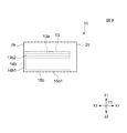
図4に示すように、前記コイル3は螺旋状に巻き回された螺旋部3aと、この螺旋部3aから実質的に側部方向(図示X1−X2方向)に延びる脚部3b1、3b2とから構成されている。
The
As shown in FIG. 4, the
図4に示すように、脚部3b1は中間部から下方向(図示Z2方向)に向かって屈曲しており、さらに螺旋部3a方向(図示X1方向)に向かって屈曲している。この下方向に向かう領域がコイル3の第1の端子部4aとなり、螺旋部3a方向に向かう領域が第2の端子部5aとなる。同様に、前記脚部3b2も中間部から下方向(図示Z2方向)に向かって屈曲しており、さらに螺旋部3a方向(図示X2方向)に向かって屈曲している。この下方向に向かう領域がコイルの第1の端子部4bとなり、螺旋部3a方向に向かう領域が第2の端子部5bとなる。
As shown in FIG. 4, the leg 3b1 is bent downward from the intermediate portion (Z2 direction in the drawing) and further bent in the direction of the
図1ないし図3に示すように、前記螺旋部3aは前記コア2の内部に密封されており、前記第1の端子部4a,4bの外側面4a1,4b1は前記コア2の側面2a,2bに露出している。また、前記第2の端子部5a,5bの下面5a1,5b1は前記コア2の下面2cに露出している。このように、図1ないし図3に示すコイル封入圧粉成型体1では、前記第1の端子部4a,4bが前記側面2a,2bに露出しており、また前記第2の端子部5a,5bが前記下面2cに露出しているため、表面実装に適したものである。また、前記コア2の側面2a,2bと下面2cの双方に、コイル3の第1の端子部および第2の端子部4a,4b,5a,5bが露出しているため、実装する際に、回路などとの接続を強固でき、確実な実装が可能となる。
As shown in FIGS. 1 to 3, the
また、図1ないし図3に示す実施の形態では、前記第1の端子部4a,4bの外側面4a1,4b1と前記コア2の側面2a,2bとは同一平坦面とされている。また、前記第2の端子部5a,5bの下面5a1,5b1と前記コア2の下面2cとは同一平坦面とされている。したがって、前記第1の端子部および第2の端子部4a,4b,5a,5bがコア2の側面2a,2bや下面2cから大きくはみ出すことがないため、コイル封入圧粉成型体1を小型化することが可能である。
In the embodiment shown in FIGS. 1 to 3, the outer surfaces 4a1 and 4b1 of the first
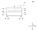
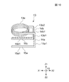
ただし、前記第2の端子部5a,5bの下面5a1,5b1が、前記コア2の下面2cと同一平坦面として形成されているものの他、図5に示すように、前記第2の端子部5a,5bが、前記コア2の下面2cよりも下方(図示Z2方向)に突出する構成のコイル封入圧粉成型体1Aとしても良い。このように構成すると、コイル封入圧粉成型体1Aを実装する際に、前記第2の端子部5a,5bと回路との接続性を良好にすることができる。
However, the lower surfaces 5a1 and 5b1 of the second
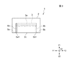
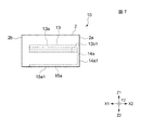
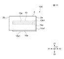
図6は、本発明の製造方法によって製造された他の形態のコイル封入圧粉成型体の第2の例を上面から見た平面図、図7は図6に示すコイル封入圧粉成型体を正面方向(図6に示すY1方向)から見た正面図、図8は図6に示すコイル封入圧粉成型体を背面方向(図6に示すY2方向)から見た正面図、図9は図1に示すコイル封入圧粉成型体を右側面方向(図6に示すX2方向)から見た側面図、図10は図1に示すコイル封入圧粉成型体の内部に封入されたコイルを示す斜視図である。 FIG. 6 is a plan view of a second example of the coil-embedded dust compact produced by the production method of the present invention as viewed from above, and FIG. 7 shows the coil-embedded dust compact shown in FIG. FIG. 8 is a front view seen from the front side (Y1 direction shown in FIG. 6), FIG. 8 is a front view seen from the back side (Y2 direction shown in FIG. 6), and FIG. The side view which looked at the coil enclosure compacting body shown in FIG. 1 from the right side surface direction (X2 direction shown in FIG. 6), FIG. 10 is the perspective view which shows the coil enclosed inside the coil enclosure compacting body shown in FIG. FIG.
図6ないし図9に示すコイル封入圧粉成型体10は、図1ないし図3に示す前記コイル封入圧粉成型体1と同じ構成要素を有して構成されているため、コイル封入圧粉成型体10のうちコイル封入圧粉成型体1と同じ構成要素には同じ符号を付して、詳しい説明を省略する。
The coil-enclosed dust compact 10 shown in FIGS. 6 to 9 has the same components as the coil-enclosed compact 1 shown in FIGS. In the
図6ないし図10に示すように、コイル封入圧粉成型体10は、立方体に形成されたコア2と、このコア2の内部に封入されたコイル13とで構成されている。
As shown in FIGS. 6 to 10, the coil-embedded
前記コア2は前記コイル13の表面を隙間なく埋めるように充填された状態でコイル13を密封しており、前記コア2と前記コイル13との間に隙間がない。そのため、前記コイル封入圧粉成型体10でもインダクタンスを高くすることが可能となっている。
前記コイル13は、例えばCuやAuなどの導電率の高い材料で形成されている。
The
The
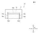
図10に示すように、前記コイル13は螺旋状に巻き回された螺旋部13aと、この螺旋部3aから実質的に側部方向(図示X1−X2方向)に延びる脚部13b1、13b2とから構成されている。
As shown in FIG. 10, the
図10に示すように、脚部13b1は中間部から下方向(図示Z2方向)に向かって屈曲しており、さらに螺旋部13a方向(図示X1方向)に向かって屈曲している。この下方向に向かう領域がコイル13の第1の第1の端子部14aとなり、螺旋部13a方向に向かう領域が第2の第2の端子部15aとなる。同様に、前記脚部13b2も中間部から下方向(図示Z2方向)に向かって屈曲しており、さらに螺旋部13a方向(図示X1方向)に向かって屈曲している。この下方向に向かう領域がコイルの第1の端子部14bとなり、螺旋部3a方向に向かう領域が第2の端子部15bとなる。
As shown in FIG. 10, the leg portion 13b1 is bent downward from the intermediate portion (Z2 direction in the drawing) and further bent in the direction of the
図6ないし図9に示すように、前記螺旋部13aは前記コア2の内部に密封されており、前記第1の端子部14a,14bの外側面4a1,4b1は前記コア2の側面2aに露出している。また、前記第2の端子部15a,15bの下面15a1,15b1は前記コア2の下面2cに露出している。このように、図6ないし図9に示すコイル封入圧粉成型体10では、前記第1の端子部14a,14bが前記側面2aに露出しており、また前記第2の端子部15a,15bが前記下面2cに露出しているため、表面実装に適したものである。また、前記コア2の側面2aと下面2cの双方に、コイル3の第1の端子部および第2の端子部14a,14b,15a,15bが露出しているため、実装する際に、回路などとの接続を強固にでき、確実な実装が可能となる。
6 to 9, the
また、図6ないし図9に示す実施の形態では、前記第1の端子部14a,14bの外側面14a1,14b1と前記コア2の側面2aとは同一平坦面とされている。また、前記第2の端子部15a,15bの下面15a1,15b1と前記コア2の下面2cとは同一平坦面とされている。したがって、前記第1の端子部および第2の端子部14a,14b,15a,15bがコア2の側面2aや下面2cから大きくはみ出すことがないため、コイル封入圧粉成型体10を小型化することが可能である。
In the embodiment shown in FIGS. 6 to 9, the outer side surfaces 14a1 and 14b1 of the first
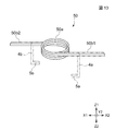
ただし、前記第2の端子部15a,15bの下面15a1,15b1が、前記コア2の下面2cと同一平坦面として形成されているものの他、図11および図12に示すように、前記第2の端子部15a,15bが、前記コア2の下面2cよりも下方(図示Z2方向)に突出する構成のコイル封入圧粉成型体10Aとしても良い。このように構成すると、コイル封入圧粉成型体1Aを実装する際に、前記第2の端子部15a,15bと回路との接続性を良好にすることができる。
However, the lower surfaces 15a1 and 15b1 of the second
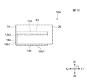
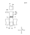
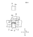
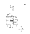
次に、図1ないし図3に示す前記コイル封入圧粉成型体1の製造方法を、図13ないし図24を用いて説明する。ここで、図14ないし図24に符号30で示すのは、後記する磁性金属粉末を圧縮して成型するための圧縮成型機である。また、符号31で示すのは前記圧縮成型機30を構成する部材であり、成型型であるダイである。また図14ないし21に示すように、このダイ31は成型型内となる穴部31aを有している。この穴部31aは、上面(図14に示すZ1方向)から見た平面形状が矩形であり、縦寸法と横寸法が、前記コイル封入圧粉成型体1の図1に示す縦寸法L1と横寸法L2とほぼ同じ寸法で構成されるものである。
Next, the manufacturing method of the said coil
図14ないし図24で符号32で示すのは下パンチである。この下パンチ32は、前記ダイ31の下方から前記穴部31a内に挿入される。この下パンチ32の上面32aは、後記する磁性金属粉末を圧縮成型する際に押圧面として機能する面である。
The
また、図14ないし図24で符合33で示すのは上パンチである。この上パンチ33は、前記ダイ31の上方から前記穴部31a内に挿入される。この上パンチ33の下面33aは、後記する磁性金属粉末を圧縮成型する際に押圧面として機能する面である。
Further, in FIG. 14 to FIG. 24,
前記下パンチ32の前記穴部31aに挿入される部分、および前記上パンチ33の前記穴部31aに挿入される部分は、ともに前記下面33aおよび上面32aと平行な面で切断した場合の断面形状が、前記穴部31aの前記平面形状と相似した矩形である。また、前記断面の縦寸法と横寸法が、前記穴部31a内に嵌合した状態で挿入可能な寸法で構成されるものである。
The cross-sectional shape when the part inserted into the
前記コイル封入圧粉成型体1を製造するには、まず図13に示すような螺旋構造体50を、例えばCuやAuなどの導電率の高い材料によって公知の方法で形成する。前記螺旋構造体50は螺旋状に巻き回された螺旋部50aと、この螺旋部50aから側部方向(図示X1−X2方向)に延びる脚部50b1、50b2とから構成されている。図13に示すように、前記脚部50b1、50b2は、前記螺旋部50aを中心として、反対方向へ延びている。
In order to manufacture the coil-embedded
次に、図13に示す螺旋構造体50を、図示一点鎖線で示すように、脚部50b1を中間部から下方向(図示Z2方向)に向かって屈曲させるとともに、脚部50b1の先端領域を螺旋部50a方向(図示X1方向)に向かって屈曲させる。
Next, in the
前記脚部50b1の前記下方向に向かう領域が、図4に示すコイル3の第1の端子部4aとなり、螺旋部50a方向に向かう領域が第2の端子部5aとして構成される。
The region of the leg portion 50b1 facing in the downward direction is the first
同様に、前記脚部50b2も中間部から下方向(図示Z2方向)に向かって屈曲させるとともに、螺旋部50a方向(図示X2方向)に向かって屈曲させる。
Similarly, the leg portion 50b2 is also bent from the intermediate portion in the downward direction (Z2 direction in the drawing) and is bent in the direction of the
前記脚部50b2の前記下方向に向かう領域がコイルの第1の端子部4bとなり、螺旋部50a方向に向かう領域が第2の端子部5bとなる。
The region of the leg portion 50b2 facing in the downward direction becomes the first
したがって、第1の端子部4a,4bは、前記螺旋部50aに対して反対方向の側部方向に形成される。
Accordingly, the first
このように、前記螺旋構造体50の脚部50b1、50b2を屈曲させて、第1の端子部および第2の端子部4a,4b,5a,5bを形成すると、図4に示す前記コイル3が形成される。なお、前記第1の端子部および第2の端子部4a,4b,5a,5bを形成する際に、前記脚部50b1,50b2を屈曲させるには、プレス機などを用いた公知の方法を使用できる。
Thus, when the leg portions 50b1 and 50b2 of the
次に図14に示すように、圧縮成型機30のダイ31の穴部31a内に嵌合した状態で挿入されている下パンチ32を下方向(図示Z2方向)に移動させて、前記穴部31aに、前記コイル3が挿入できる空間を形成する。
Next, as shown in FIG. 14, the
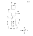
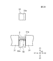
次に図15に示すように、搬送手段60によって前記コイル3を前記穴部31aの上方向(図示Z1方向)の位置に搬送する。この搬送手段60は、アーム部60aとヘッド部60bとを有して構成されており、前記ヘッド部60bには保持部60cが形成されている。この保持部60cは、例えば中空状の管で構成され、この管を通じて前記コイル3を吸引することによって前記ヘッド60bにコイル3を吸着させて保持し、コイル3を所定位置まで搬送できるように構成されたものである。
Next, as shown in FIG. 15, the
次に図16に示すように、前記搬送手段60によって、前記コイル3を前記ダイ31の穴部31a内に搬送し、前記コイル3を前記下パンチ32の上面32aに載置する。したがって、前記コイル3は、前記搬送手段60の前記ヘッド部60bと前記下パンチ32との間に位置する。このとき、前記搬送手段60の保持部60cが前記コイル3を保持した状態を維持している。また、前記コイル3の第2の端子部5a,5bの前記下面5a1,5b1は、前記下パンチ32の上面32aに当接した状態である。
Next, as shown in FIG. 16, the conveying
また、前記コイル3は、前記上面32aの中央に載置されることが好ましい。前記コイル3を前記上面32aの中央に載置すると、コイル封入圧粉成型体1の磁路長や磁路断面積のバラつきを少なくすることができるため、磁気特性のバラつきを抑えることができる。また、コイル位置が偏った場合に比べて局所的な磁気飽和を抑制できるため、インダクタンスの低下を抑制できる。さらに、磁束漏れを小さくできるため、実装された場合に、コイル封入圧粉成型体1の近傍に位置する他の電子部品に、磁束による悪影響を与え難くすることができる。
The
図16に示すように、前記コイル3が前記下パンチ32の上面32aに載置された状態では、前記コイル3の前記第1の端子部4a,4bの外側面4a1,4b1は、前記穴部31aの内側面31a1から内側に所定距離L3だけ離れた場所に位置している。
As shown in FIG. 16, in the state where the
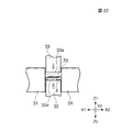
次に図17に示すように、前記搬送手段60の前記ヘッド部60bを図示矢印で示すように下方向(図示Z2方向)に移動させるとともに、前記下パンチ32を図示矢印で示すように上方向(図示Z1方向)に移動させて、前記ヘッド部60bと前記下パンチ32との間に位置する前記コイル3を上下方向から押圧する。このとき、前記コイル3に上下方向から与えられる押圧力により、前記コイル3に形成された前記第1の端子部4a,4bが側部方向(図示X1−X2方向)に広げられ、前記外側面4a1,4b1が前記穴部31aの内側面31a1に当接する。このとき図17に示すように、前記外側面4a1,4b1は、前記コイル3の螺旋部3aを基準として、互いに対向する方向に位置する内側面31a1に当接する。
Next, as shown in FIG. 17, the
次に図18に示すように、前記搬送手段60の前記保持部60cによる前記コイル3の保持を解除して前記穴部31aの上方向(図示Z1方向)に移動させ、前記コイル3を前記穴部31a内に位置する前記下パンチ32の上面32a上に載置した状態とする。
Next, as shown in FIG. 18, the holding of the
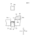
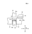
次に図19に示すように、前記搬送手段60を前記穴部31aの上方向(図示Z1方向)から移動させる。このとき、前記ダイ31の上には、前記穴部31aの側部方向(図示X1−X2方向)側には、磁性金属粉末を含有する粉体70が収納された容器80が待機している。
Next, as shown in FIG. 19, the conveying
前記粉体70は、磁性金属粉末を含有する粉末集合体71、絶縁剤72および潤滑剤73とが混合されたものである。
The
前記磁性金属粉末としては、Feなどの軟磁性を示す遷移金属や、Fe、CoおよびNiから選択される1種以上を含む合金、例えばパーマロイ(Fe−Ni合金)、センダスト(Fe−Si−Al合金)、ケイ素鋼(Fe−Si合金)、Fe−Co合金、Fe−P合金などの合金からなる粉末を使用することができる。 Examples of the magnetic metal powder include transition metals exhibiting soft magnetism such as Fe, alloys containing at least one selected from Fe, Co and Ni, such as permalloy (Fe—Ni alloy), Sendust (Fe—Si—Al). Alloy), silicon steel (Fe—Si alloy), Fe—Co alloy, Fe—P alloy and other powders can be used.
前記磁性金属粉末は、前記金属や合金を、例えば水アトマイズ法、油アトマイズ法、ガスアトマイズ法、電解法、回転円板法、双ロール法、回転電極法などの公知の方法によって製造できる。この磁性金属粉末の平均粒径は、6〜200μmの範囲内、好ましくは15μmである。また、この磁性金属粉末は、球体に近いほど、後記する図20ないし図22に示す工程において充填密度を向上することができるため好ましい。 The magnetic metal powder can be produced by known methods such as the water atomization method, the oil atomization method, the gas atomization method, the electrolysis method, the rotating disk method, the twin roll method, and the rotating electrode method. The average particle size of the magnetic metal powder is in the range of 6 to 200 μm, preferably 15 μm. Further, the closer the magnetic metal powder is to a sphere, the better the packing density can be improved in the steps shown in FIGS.
前記粉末集合体71は、例えば前記磁性金属粉末としてFeが74.43atm%の他、Crを1.96atm%、Pを9.04atm%、Cを2.16atm%、Bを7.54atm%、Siを4.87atm%含有したものを使用できる。 For example, the powder aggregate 71 includes, as the magnetic metal powder, Fe of 74.43 atm%, Cr of 1.96 atm%, P of 9.04 atm%, C of 2.16 atm%, and B of 7.54 atm%, A material containing 4.87 atm% Si can be used.
前記絶縁剤72は、前記粉末集合体71を構成するためのバインダーとしての機能、および前記粉末集合体71を構成する前記磁性金属粉末間の絶縁を図る機能を有する。前記磁性金属粉末間で電流が流れると、前記磁性金属粉末に渦電流が発生し易くなり、この渦電流によって鉄損が高くなる(渦電流損失)。前記絶縁剤72は、この渦電流損失を抑制するための機能を有するものである。前記絶縁剤72は有機材料を使用でき、例えばアクリル樹脂、エポキシ樹脂、シリコン樹脂、ポリアミド樹脂およびポリイミド樹脂などを使用でき、好ましくは熱硬化性樹脂が使用される。 The insulating material 72 has a function as a binder for constituting the powder aggregate 71 and a function for insulating between the magnetic metal powders constituting the powder aggregate 71. When a current flows between the magnetic metal powders, eddy currents are easily generated in the magnetic metal powder, and the iron loss increases due to the eddy currents (eddy current loss). The insulating material 72 has a function for suppressing this eddy current loss. The insulating material 72 can use an organic material, such as an acrylic resin, an epoxy resin, a silicon resin, a polyamide resin, and a polyimide resin, and preferably a thermosetting resin.
前記潤滑剤73は、後記する図20ないし図22に示す工程において、前記粉末集合体71の潤滑性を向上させることによって充填密度を向上させる機能を有する。前記潤滑剤73には、ステアリン酸亜鉛、ステアリン酸アルミニウム、ステアリン酸マグネシウム、ステアリン酸カルシウム、ステアリン酸ストロンチウム、ステアリン酸バリウム、Ca、Zn、Al、Mgなどを使用できる。 The lubricant 73 has a function of improving the packing density by improving the lubricity of the powder aggregate 71 in the steps shown in FIGS. As the lubricant 73, zinc stearate, aluminum stearate, magnesium stearate, calcium stearate, strontium stearate, barium stearate, Ca, Zn, Al, Mg, or the like can be used.
前記粉末集合体71、前記絶縁剤72および前記潤滑剤73の組成比としては、例えば前記粉末集合体71を98〜99wt%、前記絶縁剤72を1〜2wt%、前記潤滑剤73を0.1〜0.5wt%で、全体として100wt%となる組成比が挙げられる。
The composition ratio of the powder aggregate 71, the insulating material 72 and the lubricant 73 is, for example, 98 to 99 wt% for the
前記容器80の底面80aには、穴部80bが形成されている。図19に示す状態では、前記穴部80bは前記ダイ31の上面31bによって塞がれているため、前記容器80内に収納されている前記粉体70は、容器80内に収納された状態を維持している。
A
図19に示す状態で、前記容器80を図示矢印に示すように、前記ダイ31の前記穴部31a方向(図示X1方向)に移動させ、前記容器80の前記穴部80bが前記ダイ31の前記穴部31aと重なるようにすると、図20に示すように、前記容器80内に収納されていた前記粉体70が、前記穴部80bを通過して前記穴部31a内に落下し、前記穴部31a内に前記粉体70が充填される。このようにして、前記コイル3を前記粉体70によって埋める。このとき、前記粉体70は前記穴部31a内で、前記下パンチ32の上面32a上に載置されているコイル3の周囲を隙間なく充填される。また、前記コイル3の前記第1の端子部4a,4bの前記外側面4a1,4b1は、前記ダイ31に形成された前記穴部31aの内側面31a1に当接しているため、前記粉体70が前記外側面4a1,4b1と前記内側面31a1との間に充填されることはない。
In the state shown in FIG. 19, the
前記粉体70が前記穴部31a内に所定量だけ充填されたときに、図20で示す矢印に示すように、前記容器80を前記ダイ31方向(図示X2方向)に移動させると、前記容器80の前記穴部80bが前記ダイ31の上面31bによって塞がれ、前記粉体70の前記穴部31a内への充填が停止される。このときの状態を示したのが図21である。
When the
次に図22に示すように、前記穴部31a内に前記上パンチ33を図示矢印に示すように下方向(図示Z2方向)に下降させ、前記穴部31a内に充填されている前記粉体70を前記上パンチ33の下面33aによって押圧するとともに、前記下パンチ32を図示矢印に示すように上方向(図示Z1方向)に上昇させ、前記穴部31a内に充填されている前記粉体70を前記下パンチ32の上面32aで押圧する。前記穴部31a内に充填された前記粉体70は、前記穴部31a内で前記上面32a、および前記下面33aによって押圧されることにより、圧縮される。
Next, as shown in FIG. 22, the
次に図23に示すように、前記下パンチ32の前記上面32aおよび前記上パンチ33の前記下面33aによる前記粉体70の押圧を停止し、前記上パンチ33を図示矢印に示すように上方向(図示Z1方向)へ上昇させ、記穴部31a内から前記上パンチ33を抜いた後、図24に示すように、前記下パンチ32を図示矢印に示すように上方向(図示Z1方向)に上昇させ、前記下パンチ32の上面32a上に載置された圧縮状態の前記粉体70を、前記コイル3が封入された状態のまま取り出す。
Next, as shown in FIG. 23, the pressing of the
次に、この圧縮状態の前記粉体70を加熱して、前記絶縁剤72を硬化させると、図1ないし図3に示すコイル封入圧粉成型体1が製造される。前記粉体70の加熱温度は、350〜450℃の範囲内、例えば400℃である。なお、この加熱時に、前記粉体70を構成する前記絶縁剤72の一部が気化し、加熱終了時には加熱前の絶縁剤72の量に対して大部分が残る。また、この加熱時に、前記粉体70を構成する前記潤滑剤73のほとんどが気化する。このように前記粉体70を圧縮成型すると、図1ないし図3に示す前記コイル封入圧粉成型体1の前記コア2が形成され、前記コイル封入圧粉成型体1が製造される。
Next, when the
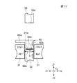
図6ないし図9に示すコイル封入圧粉成型体10を製造するには、まず図25に示すような螺旋構造体150を、例えばCuやAuなどの導電率の高い材料によって公知の方法で形成する。前記螺旋構造体150は螺旋状に巻き回された螺旋部150aと、この螺旋部150aから側部方向(図示X2方向)に延びる脚部150b1、150b2とから構成されている。図25に示すように、前記脚部150b1、150b2は、前記螺旋部50aを中心として、同じ方向(図示X2方向)へ延びている。
In order to manufacture the coil-embedded compact 10 shown in FIGS. 6 to 9, first, a
次に、図25に示す螺旋構造体150を、図示一点鎖線で示すように、脚部150b1を中間部から下方向(図示Z2方向)に向かって屈曲させるとともに、脚部150b1の先端領域を螺旋部150a方向(図示X1方向)に向かって屈曲させる。
Next, in the
前記脚部150b1の前記下方向に向かう領域が、図10に示すコイル13の第1の端子部14aとなり、螺旋部150a方向に向かう領域が第2の端子部15aとして構成される。
A region of the leg portion 150b1 facing in the downward direction is a first
同様に、前記脚部150b2も中間部から下方向(図示Z2方向)に向かって屈曲させるとともに、螺旋部150a方向(図示X1方向)に向かって屈曲させる。
Similarly, the leg 150b2 is also bent from the intermediate portion in the downward direction (Z2 direction in the drawing) and is bent in the direction of the
前記脚部150b2の前記下方向に向かう領域がコイルの第1の端子部14bとなり、螺旋部150a方向に向かう領域が第2の端子部15bとなる。
The region of the leg portion 150b2 facing in the downward direction is the first
したがって、第1の端子部14a,14bは、前記螺旋部150aに対して同じ方向の側部方向に形成される。
Accordingly, the first
このように、前記螺旋構造体150の脚部150b1、150b2を屈曲させて、第1の端子部および第2の端子部14a,14b,15a,15bを形成すると、図4に示す前記コイル13が形成される。なお、前記第1の端子部および第2の端子部14a,14b,15a,15bを形成する際に、前記脚部150b1,150b2を屈曲させるには、プレス機などを用いた公知の方法を使用できる。
In this way, when the leg portions 150b1 and 150b2 of the
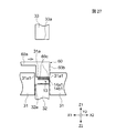
その後は、図1ないし図3に示すコイル封入圧粉成型体1の製造方法である図14ないし図24に示す製造方法とほぼ同様の製造方法によって製造できる。ただし、図6ないし図9に示す前記コイル封入圧縮成型体10を製造するには、コイル封入圧粉成型体1の製造方法である図16に示す工程で、図26に示すように前記コイル3に換えて前記コイル13を前記ダイ31の前記穴部31a内で、前記下パンチ32の上面32a上に載置する。このとき、前記コイル13の第1の端子部14a,14bの外側面14a1,14b1が、前記穴部31aの内側面31a1に当接していない場合には、図27に示すように、前記搬送手段60を図示矢印に示すように前記穴部31aの内側面31a1方向(図示X2方向)に移動させて、前記コイル13の第1の端子部14a,14bの外側面14a1,14b1を、前記穴部31aの内側面31a1に当接させる。このとき図27に示すように、前記外側面14a1,14b1は、前記コイル13の螺旋部13aを基準として、互いに同じ方向に位置する内側面31a1に当接する。
Thereafter, it can be manufactured by a manufacturing method substantially similar to the manufacturing method shown in FIGS. 14 to 24, which is a manufacturing method of the coil-embedded compact 1 shown in FIGS. However, in order to manufacture the coil-encapsulated compression molded
その後は、前記コイル封入圧粉成型体1の製造方法を示す図18ないし図24と同様の工程により、前記コイル封入圧粉成型体10を製造できる。
Thereafter, the coil-enclosed powder compact 10 can be manufactured by the same steps as those shown in FIGS. 18 to 24 showing the method for manufacturing the coil-enclosed
また、図5に示すコイル封入圧縮成型体1Aや、図11および図12に示すコイル封入圧縮成型体10Aを製造するには、前記下パンチ32の前記上面32aに、前記第2の端子部5a,5b、および15a,15bの大きさや形状に合わせた溝を形成し、この溝に前記第2の端子部5a,5b、および15a,15bを嵌合させた状態で、前記粉体70の圧縮成型を行えば良い。
In order to manufacture the coil-encapsulated compression molded
本発明のコイル封入圧粉成型体1,1A,10,10Aの製造方法では、コイル3,13の周囲に前記粉体70を充填した後、この粉体70の圧縮工程を1度行うだけで、コア2を圧縮成型できるため、工程数を少なくでき、容易に製造することができる。
In the method of manufacturing the coil-enclosed
また、前記コイル3,13の前記第1の端子部4a,4b、14a,14bの前記外側面4a1,4b1、14a1,14b1は、前記ダイ31に形成された前記穴部31aの内側面31a1に当接しているため、前記粉体70が前記外側面4a1,4b1、14a1,14b1と前記内側面31a1との間に充填されることはない。そのため、前記コア2の側面2aや2bに、前記第1の端子部4a,4b、14a,14bの前記外側面4a1,4b1、14a1,14b1を露出させることが可能となるため、表面実装に適したコイル封入圧粉成型体1,1A,10,10Aを容易に製造できる。
Further, the outer side surfaces 4a1, 4b1, 14a1, and 14b1 of the first
また、コイル3,13の脚部3b1,3b2、13b1,13b2を屈曲させて、コイル3,13にあらかじめ端子部4a,4b,5a,5b、14a,14b,15a,15bを形成しているため、コイル3,13全体をダイ31の穴部31a内に載置することができる。そのため、前記特許文献1に開示された製造方法のように、コイル3,13の脚部3b1,3b2、13b1,13b2を下型枠と上型枠との間に挟みこんだ状態で粉体70の圧縮成型を行う必要がないため、ダイ31を下型枠と上型枠とに2分割した構造とする必要がなく、一体的な構造とすることができるため、ダイ31の製造コストを低廉にすることが可能となる。
Further, the leg portions 3b1, 3b2, 13b1, 13b2 of the
また、コア2を成型するための粉体70の圧縮成型工程時に、前記ダイ31の穴部31a内にコイル3,13全体を載置できるので、コイル3,13が上下方向に移動しても、コイル3,13の上下移動に合わせてダイ31を移動させ必要がないため、ダイ31の上下移動のためにの油圧装置などのダイ31の駆動手段を設ける必要がなく、設備を簡単な構造とすることができるとともに、設備費用も低廉にすることが可能となる。
Further, since the
さらに、コイル3,13の脚部3b1,3b2、13b1,13b2を屈曲させて、コイル3にあらかじめ端子部4a,4b,5a,5b、14a,14b,15a,15bを形成しているため、コイル3,13全体をダイ31の穴部31a内に載置できるため、表面実装に適した構造のコイル封入圧粉成型体1,1A,10,10Aを容易に製造できる。特に、前記第2の端子部5a,5b、および15a,15bが形成されているため、この第2の端子部5a,5b、および15a,15bの下面5a1,5b1,15a1,15b1を下パンチ32の上面32aに接触した状態で粉体70を圧縮成型できるため、前記下面5a1,5b1,15a1,15b1を、前記コア2の下面2cから現すことができるため、表面実装に適したコイル封入圧粉成型体1、1A,10,10Aとすることが可能となる。
Further, the leg portions 3b1, 3b2, 13b1, 13b2 of the
また、コア2が形成されていないときに、コイル3,13単体の状態時に端子部4a,4b,5a,5bを形成しているため、端子部4a,4b,5a,5b、14a,14b,15a,15bを曲げる工程の際に、コア2が割れてしまい、製造歩留まりが低下するといった問題は発生しないため、製造歩留まりの向上を図ることができる。
Further, when the
1,1A,10,10A コイル封入圧粉成型体
2 コア
3 コイル
3a 螺旋部
3b 脚部
4a,4b,14a,14b 第1の端子部
4a1,4b1,14a1,14b1 外側面
5a,5b,15a,15b 第2の端子部
31 ダイ
31a 穴部
32 下パンチ
33 上パンチ
50,150 螺旋構造体
50a,150a 螺旋部
50b1,50b2,150b1,150b2 脚部
70 粉体
DESCRIPTION OF
Claims (4)
(a)螺旋部と、前記螺旋部から側部方向に向かって延びる脚部とを有する螺旋構造体の前記脚部を前記螺旋部の下方に屈曲させて、第1の端子部と螺旋部とを有するコイルを形成する工程と、
(b)前記コイルを成型型内に載置し、このとき前記コイルの前記第1の端子部の外側面を、前記成型型内の内側面に当接させる工程と、
(c)前記成型型内に磁性金属粉末を充填し、前記コイルを前記磁性金属粉末で埋める工程と、
(d)前記金属粉末を圧縮成型する工程、 The manufacturing method of the coil enclosure compacting body characterized by having the following processes.
(A) The first terminal portion and the spiral portion are formed by bending the leg portion of the spiral structure having a spiral portion and a leg portion extending in the lateral direction from the spiral portion. Forming a coil having:
(B) placing the coil in a mold, and contacting the outer surface of the first terminal portion of the coil with the inner surface of the mold;
(C) filling the mold with magnetic metal powder and filling the coil with the magnetic metal powder;
(D) a step of compression molding the metal powder;
Priority Applications (3)
| Application Number | Priority Date | Filing Date | Title |
|---|---|---|---|
| JP2004106181A JP4301988B2 (en) | 2004-03-31 | 2004-03-31 | Method for producing a coil-filled green compact |
| KR1020050023883A KR100743877B1 (en) | 2004-03-31 | 2005-03-23 | Method for manufacturing pressed powder body enclosing coil |
| CNB2005100600779A CN100428377C (en) | 2004-03-31 | 2005-03-31 | Method for making press-powder forming body for coil enclosure |
Applications Claiming Priority (1)
| Application Number | Priority Date | Filing Date | Title |
|---|---|---|---|
| JP2004106181A JP4301988B2 (en) | 2004-03-31 | 2004-03-31 | Method for producing a coil-filled green compact |
Publications (2)
| Publication Number | Publication Date |
|---|---|
| JP2005294461A true JP2005294461A (en) | 2005-10-20 |
| JP4301988B2 JP4301988B2 (en) | 2009-07-22 |
Family
ID=35050020
Family Applications (1)
| Application Number | Title | Priority Date | Filing Date |
|---|---|---|---|
| JP2004106181A Expired - Fee Related JP4301988B2 (en) | 2004-03-31 | 2004-03-31 | Method for producing a coil-filled green compact |
Country Status (3)
| Country | Link |
|---|---|
| JP (1) | JP4301988B2 (en) |
| KR (1) | KR100743877B1 (en) |
| CN (1) | CN100428377C (en) |
Cited By (19)
| Publication number | Priority date | Publication date | Assignee | Title |
|---|---|---|---|---|
| JP2009123927A (en) * | 2007-11-15 | 2009-06-04 | Taiyo Yuden Co Ltd | Inductor and production process therefor |
| JP2009200435A (en) * | 2008-02-25 | 2009-09-03 | Taiyo Yuden Co Ltd | Surface-mounting coil member |
| JP2009267350A (en) * | 2008-04-04 | 2009-11-12 | Toko Inc | Method for manufacturing molded coil |
| JP2010053372A (en) * | 2008-08-26 | 2010-03-11 | Nec Tokin Corp | Iron-nickel alloy powder, method for producing the same, and powder magnetic core for inductor using the alloy powder |
| JP2010177492A (en) * | 2009-01-30 | 2010-08-12 | Toko Inc | Method for manufacturing mold coil |
| WO2013183183A1 (en) * | 2012-06-04 | 2013-12-12 | アイトリックス株式会社 | Compressed powder molded inductor member production device, production method for compressed powder molded inductor member, and compressed powder molded inductor member |
| JP2014049597A (en) * | 2012-08-31 | 2014-03-17 | Toko Inc | Surface mounting inductor and manufacturing method therefor |
| US8695209B2 (en) | 2009-04-10 | 2014-04-15 | Toko, Inc. | Method of producing a surface-mount inductor |
| JP2015002228A (en) * | 2013-06-14 | 2015-01-05 | 東光株式会社 | Manufacturing method of surface mount inductor |
| JP2015225887A (en) * | 2014-05-26 | 2015-12-14 | 太陽誘電株式会社 | Coil component and electronic apparatus |
| JP2016119385A (en) * | 2014-12-20 | 2016-06-30 | 東光株式会社 | Surface mounting inductor and method of manufacturing the same |
| WO2016121950A1 (en) * | 2015-01-30 | 2016-08-04 | 株式会社村田製作所 | Magnetic powder and production method thereof, magnetic core and production method thereof, coil component and motor |
| WO2016121951A1 (en) * | 2015-01-30 | 2016-08-04 | 株式会社村田製作所 | Magnetic powder and production method thereof, magnetic core and production method thereof, coil component and motor |
| TWI603350B (en) * | 2014-10-01 | 2017-10-21 | Honor Rich Scient Corp | Inductive process |
| JP2019004174A (en) * | 2018-09-05 | 2019-01-10 | 太陽誘電株式会社 | Coil component and electronic apparatus |
| JP2019201220A (en) * | 2018-09-05 | 2019-11-21 | 太陽誘電株式会社 | Coil component and electronic device |
| WO2020121421A1 (en) * | 2018-12-11 | 2020-06-18 | アルプスアルパイン株式会社 | Inductance element |
| JP2024056376A (en) * | 2022-10-11 | 2024-04-23 | 株式会社村田製作所 | Inductors |
| DE112022005178T5 (en) | 2021-10-29 | 2024-08-08 | Panasonic Intellectual Property Management Co., Ltd. | Inductance and process for its manufacture |
Families Citing this family (6)
| Publication number | Priority date | Publication date | Assignee | Title |
|---|---|---|---|---|
| KR100908600B1 (en) * | 2007-03-23 | 2009-07-21 | 송만호 | Coil-embedded circuit board and power module using same |
| JP5417074B2 (en) | 2009-07-23 | 2014-02-12 | 日立粉末冶金株式会社 | Powder magnetic core and manufacturing method thereof |
| JP5874133B2 (en) * | 2013-03-08 | 2016-03-02 | アルプス・グリーンデバイス株式会社 | Inductance element manufacturing method |
| JP5874134B2 (en) * | 2013-03-11 | 2016-03-02 | アルプス・グリーンデバイス株式会社 | Inductance element |
| CN105489362A (en) * | 2014-10-11 | 2016-04-13 | 诚钜科技有限公司 | Inductance technology |
| DE102018218149A1 (en) * | 2018-10-23 | 2020-04-23 | Fraunhofer-Gesellschaft zur Förderung der angewandten Forschung e.V. | COIL-TOOTH MODULE AND METHOD FOR THE PRODUCTION THEREOF |
Family Cites Families (6)
| Publication number | Priority date | Publication date | Assignee | Title |
|---|---|---|---|---|
| JP4684461B2 (en) * | 2000-04-28 | 2011-05-18 | パナソニック株式会社 | Method for manufacturing magnetic element |
| JP2002324714A (en) | 2001-02-21 | 2002-11-08 | Tdk Corp | Coil sealed dust core and its manufacturing method |
| JP2002289423A (en) * | 2001-03-23 | 2002-10-04 | Mosutetsuku:Kk | Electronic part and its manufacturing method |
| JP4049246B2 (en) | 2002-04-16 | 2008-02-20 | Tdk株式会社 | Coil-enclosed magnetic component and method for manufacturing the same |
| JP2004153068A (en) | 2002-10-31 | 2004-05-27 | Toko Inc | Dust inductor and its manufacturing method |
| JP2005142380A (en) | 2003-11-07 | 2005-06-02 | Nec Tokin Corp | Coil component and method for manufacturing the same |
-
2004
- 2004-03-31 JP JP2004106181A patent/JP4301988B2/en not_active Expired - Fee Related
-
2005
- 2005-03-23 KR KR1020050023883A patent/KR100743877B1/en not_active Expired - Fee Related
- 2005-03-31 CN CNB2005100600779A patent/CN100428377C/en not_active Expired - Fee Related
Cited By (26)
| Publication number | Priority date | Publication date | Assignee | Title |
|---|---|---|---|---|
| JP2009123927A (en) * | 2007-11-15 | 2009-06-04 | Taiyo Yuden Co Ltd | Inductor and production process therefor |
| JP2009200435A (en) * | 2008-02-25 | 2009-09-03 | Taiyo Yuden Co Ltd | Surface-mounting coil member |
| JP2009267350A (en) * | 2008-04-04 | 2009-11-12 | Toko Inc | Method for manufacturing molded coil |
| JP2010053372A (en) * | 2008-08-26 | 2010-03-11 | Nec Tokin Corp | Iron-nickel alloy powder, method for producing the same, and powder magnetic core for inductor using the alloy powder |
| JP2010177492A (en) * | 2009-01-30 | 2010-08-12 | Toko Inc | Method for manufacturing mold coil |
| US8695209B2 (en) | 2009-04-10 | 2014-04-15 | Toko, Inc. | Method of producing a surface-mount inductor |
| US9165710B2 (en) | 2009-04-10 | 2015-10-20 | Toko, Inc. | Method of producing a surface-mount inductor |
| WO2013183107A1 (en) * | 2012-06-04 | 2013-12-12 | アイトリックス株式会社 | Compressed powder molded inductor member production device, production method for compressed powder molded inductor member, and compressed powder molded inductor member |
| WO2013183183A1 (en) * | 2012-06-04 | 2013-12-12 | アイトリックス株式会社 | Compressed powder molded inductor member production device, production method for compressed powder molded inductor member, and compressed powder molded inductor member |
| JP2014049597A (en) * | 2012-08-31 | 2014-03-17 | Toko Inc | Surface mounting inductor and manufacturing method therefor |
| JP2015002228A (en) * | 2013-06-14 | 2015-01-05 | 東光株式会社 | Manufacturing method of surface mount inductor |
| JP2015225887A (en) * | 2014-05-26 | 2015-12-14 | 太陽誘電株式会社 | Coil component and electronic apparatus |
| TWI603350B (en) * | 2014-10-01 | 2017-10-21 | Honor Rich Scient Corp | Inductive process |
| JP2016119385A (en) * | 2014-12-20 | 2016-06-30 | 東光株式会社 | Surface mounting inductor and method of manufacturing the same |
| WO2016121951A1 (en) * | 2015-01-30 | 2016-08-04 | 株式会社村田製作所 | Magnetic powder and production method thereof, magnetic core and production method thereof, coil component and motor |
| WO2016121950A1 (en) * | 2015-01-30 | 2016-08-04 | 株式会社村田製作所 | Magnetic powder and production method thereof, magnetic core and production method thereof, coil component and motor |
| JPWO2016121951A1 (en) * | 2015-01-30 | 2017-12-07 | 株式会社村田製作所 | Magnetic powder and manufacturing method thereof, magnetic core and manufacturing method thereof, coil component, and motor |
| JPWO2016121950A1 (en) * | 2015-01-30 | 2017-12-21 | 株式会社村田製作所 | Magnetic powder and manufacturing method thereof, magnetic core and manufacturing method thereof, coil component, and motor |
| US10758982B2 (en) | 2015-01-30 | 2020-09-01 | Murata Manufacturing Co., Ltd. | Magnetic powder and production method thereof, magnetic core and production method thereof, coil component and motor |
| US10767249B2 (en) | 2015-01-30 | 2020-09-08 | Murata Manufacturing Co., Ltd. | Magnetic powder and production method thereof, magnetic core and production method thereof, coil component and motor |
| JP2019004174A (en) * | 2018-09-05 | 2019-01-10 | 太陽誘電株式会社 | Coil component and electronic apparatus |
| JP2019201220A (en) * | 2018-09-05 | 2019-11-21 | 太陽誘電株式会社 | Coil component and electronic device |
| WO2020121421A1 (en) * | 2018-12-11 | 2020-06-18 | アルプスアルパイン株式会社 | Inductance element |
| DE112022005178T5 (en) | 2021-10-29 | 2024-08-08 | Panasonic Intellectual Property Management Co., Ltd. | Inductance and process for its manufacture |
| JP2024056376A (en) * | 2022-10-11 | 2024-04-23 | 株式会社村田製作所 | Inductors |
| JP7729306B2 (en) | 2022-10-11 | 2025-08-26 | 株式会社村田製作所 | inductor |
Also Published As
| Publication number | Publication date |
|---|---|
| CN100428377C (en) | 2008-10-22 |
| CN1677585A (en) | 2005-10-05 |
| KR100743877B1 (en) | 2007-07-30 |
| KR20060044586A (en) | 2006-05-16 |
| JP4301988B2 (en) | 2009-07-22 |
Similar Documents
| Publication | Publication Date | Title |
|---|---|---|
| JP4301988B2 (en) | Method for producing a coil-filled green compact | |
| JP4099340B2 (en) | Manufacturing method of coil-embedded dust core | |
| CN101896982B (en) | Inductance part and method for manufacturing the same | |
| TWI564918B (en) | Surface-mounted inductor and manufacturing method thereof | |
| JP4049246B2 (en) | Coil-enclosed magnetic component and method for manufacturing the same | |
| JP6890260B2 (en) | Inductor parts and their manufacturing methods | |
| TWI496173B (en) | Inductance element | |
| JP3769183B2 (en) | Coil parts | |
| JP2006060087A (en) | Coil-encapsulating powder magnetic core | |
| JP5894119B2 (en) | Manufacturing method of surface mount inductor | |
| JP2004153068A (en) | Dust inductor and its manufacturing method | |
| JP3181451U (en) | Inductor | |
| JP4768372B2 (en) | Coil-enclosed magnetic component and method for manufacturing the same | |
| JP2014049598A (en) | Surface mounting inductor and manufacturing method therefor | |
| JP4768373B2 (en) | Coil-enclosed magnetic component and method for manufacturing the same | |
| JP6519989B2 (en) | Inductor element | |
| JP2006013065A (en) | Inductor and its manufacturing method | |
| US20060009000A1 (en) | Method of fabricating coil-embedded inductor | |
| JP5407817B2 (en) | Coil parts manufacturing method | |
| WO2013183183A1 (en) | Compressed powder molded inductor member production device, production method for compressed powder molded inductor member, and compressed powder molded inductor member | |
| JP2006228825A (en) | Inductor and its manufacturing method | |
| JP2003068513A (en) | Soft magnetic powder for metal composite core | |
| JP2019062097A (en) | Inductor and manufacturing method thereof | |
| JP2006210847A (en) | Compressed powder magnetic core and manufacturing method thereof | |
| US7836578B2 (en) | Method of fabricating coil-embedded inductor |
Legal Events
| Date | Code | Title | Description |
|---|---|---|---|
| A621 | Written request for application examination |
Free format text: JAPANESE INTERMEDIATE CODE: A621 Effective date: 20060904 |
|
| A977 | Report on retrieval |
Free format text: JAPANESE INTERMEDIATE CODE: A971007 Effective date: 20090116 |
|
| A131 | Notification of reasons for refusal |
Free format text: JAPANESE INTERMEDIATE CODE: A131 Effective date: 20090120 |
|
| A521 | Written amendment |
Free format text: JAPANESE INTERMEDIATE CODE: A523 Effective date: 20090306 |
|
| TRDD | Decision of grant or rejection written | ||
| A01 | Written decision to grant a patent or to grant a registration (utility model) |
Free format text: JAPANESE INTERMEDIATE CODE: A01 Effective date: 20090407 |
|
| A01 | Written decision to grant a patent or to grant a registration (utility model) |
Free format text: JAPANESE INTERMEDIATE CODE: A01 |
|
| A61 | First payment of annual fees (during grant procedure) |
Free format text: JAPANESE INTERMEDIATE CODE: A61 Effective date: 20090421 |
|
| FPAY | Renewal fee payment (event date is renewal date of database) |
Free format text: PAYMENT UNTIL: 20120501 Year of fee payment: 3 |
|
| R150 | Certificate of patent or registration of utility model |
Ref document number: 4301988 Country of ref document: JP Free format text: JAPANESE INTERMEDIATE CODE: R150 Free format text: JAPANESE INTERMEDIATE CODE: R150 |
|
| FPAY | Renewal fee payment (event date is renewal date of database) |
Free format text: PAYMENT UNTIL: 20120501 Year of fee payment: 3 |
|
| S111 | Request for change of ownership or part of ownership |
Free format text: JAPANESE INTERMEDIATE CODE: R313111 |
|
| FPAY | Renewal fee payment (event date is renewal date of database) |
Free format text: PAYMENT UNTIL: 20120501 Year of fee payment: 3 |
|
| R350 | Written notification of registration of transfer |
Free format text: JAPANESE INTERMEDIATE CODE: R350 |
|
| FPAY | Renewal fee payment (event date is renewal date of database) |
Free format text: PAYMENT UNTIL: 20120501 Year of fee payment: 3 |
|
| FPAY | Renewal fee payment (event date is renewal date of database) |
Free format text: PAYMENT UNTIL: 20130501 Year of fee payment: 4 |
|
| R250 | Receipt of annual fees |
Free format text: JAPANESE INTERMEDIATE CODE: R250 |
|
| FPAY | Renewal fee payment (event date is renewal date of database) |
Free format text: PAYMENT UNTIL: 20140501 Year of fee payment: 5 |
|
| R250 | Receipt of annual fees |
Free format text: JAPANESE INTERMEDIATE CODE: R250 |
|
| R250 | Receipt of annual fees |
Free format text: JAPANESE INTERMEDIATE CODE: R250 |
|
| R250 | Receipt of annual fees |
Free format text: JAPANESE INTERMEDIATE CODE: R250 |
|
| R250 | Receipt of annual fees |
Free format text: JAPANESE INTERMEDIATE CODE: R250 |
|
| S111 | Request for change of ownership or part of ownership |
Free format text: JAPANESE INTERMEDIATE CODE: R313111 |
|
| R350 | Written notification of registration of transfer |
Free format text: JAPANESE INTERMEDIATE CODE: R350 |
|
| S533 | Written request for registration of change of name |
Free format text: JAPANESE INTERMEDIATE CODE: R313533 |
|
| R350 | Written notification of registration of transfer |
Free format text: JAPANESE INTERMEDIATE CODE: R350 |
|
| LAPS | Cancellation because of no payment of annual fees |