JP2005294130A - Control equipment - Google Patents
Control equipment Download PDFInfo
- Publication number
- JP2005294130A JP2005294130A JP2004109573A JP2004109573A JP2005294130A JP 2005294130 A JP2005294130 A JP 2005294130A JP 2004109573 A JP2004109573 A JP 2004109573A JP 2004109573 A JP2004109573 A JP 2004109573A JP 2005294130 A JP2005294130 A JP 2005294130A
- Authority
- JP
- Japan
- Prior art keywords
- external
- control device
- internal
- connector
- varistor
- Prior art date
- Legal status (The legal status is an assumption and is not a legal conclusion. Google has not performed a legal analysis and makes no representation as to the accuracy of the status listed.)
- Pending
Links
Images

Landscapes
- Connections Arranged To Contact A Plurality Of Conductors (AREA)
- Details Of Connecting Devices For Male And Female Coupling (AREA)
Abstract
【課題】
制御機器の外でバリスタの取り付け作業ができる制御機器を提供することにある。
【解決手段】
制御装置3と内部配線6で接続される外部インターフェース中継端子台4と、外部インターフェース中継端子台4と外部の設備とを接続する外部配線7とを備え、外部インターフェース中継端子台4が制御機器1に固定された本体13と本体13にコネクタ構造で取り付けられた外部端子コネクタ14で構成され、外部端子コネクタ14にアースバー20を内蔵させ、内部接点12とアースバー20とをバリスタ10で接続した。
【選択図】図3
【Task】
An object of the present invention is to provide a control device capable of attaching a varistor outside the control device.
[Solution]
The external interface relay terminal block 4 connected to the control device 3 by the internal wiring 6 and the external wiring 7 for connecting the external interface relay terminal block 4 and external equipment are provided. The external interface relay terminal block 4 is the control device 1. The external terminal connector 14 is attached to the main body 13 with a connector structure. The ground terminal 20 is built in the external terminal connector 14, and the internal contact 12 and the ground bar 20 are connected by the varistor 10.
[Selection] Figure 3
Description
本発明は、主として一般産業,通信分野における制御機器に係り、外部インターフェース部の静電対策,サージ対策を施した保守作業の容易なコネクタを備えた制御機器に関する。 The present invention mainly relates to a control device in the general industry and the communication field, and more particularly to a control device including a connector with an easy-to-maintenance work that is provided with countermeasures against static electricity and surge in an external interface unit.
主に一般産業や通信分野における制御機器は、製品の保護と隣接製品の保護を行うために静電対策やサージ対策を施す必要がある。この静電対策やサージ対策として、バリスタを外部インターフェース端子台の接点部と筐体に取り付けた専用アースバー部に取り付け、アースバーから筐体の集合クランプに配線するのが一般的である。 Control equipment mainly in the general industry and the communication field needs to take countermeasures against static electricity and surges in order to protect products and adjacent products. As a countermeasure against static electricity or surge, it is common to attach a varistor to a contact portion of the external interface terminal block and a dedicated earth bar portion attached to the casing, and wire the ground bar to the collective clamp of the casing.
〔特許文献1〕には、補助用プリント配線基板にはバリスタ(電子部品,サージ吸収素子に相当)が実装され、ターミナルとバリスタとが配線パターンにより電気的に接続された端子台装置が開示されている。 [Patent Document 1] discloses a terminal block device in which a varistor (an electronic component, corresponding to a surge absorbing element) is mounted on an auxiliary printed wiring board, and the terminal and the varistor are electrically connected by a wiring pattern. ing.
従来の外部インターフェース端子台の接点部と専用アースバーにバリスタを取り付ける方式は、制御機器内に外部インターフェース端子台と、専用アースバーを取り付けた後、バリスタを取り付ける手順で作業を進めるものであるため、小型化された製品では、制御機器内の狭いエリアでの作業となるため作業性は低下し、作業安全上でも問題点がある。また、バリスタを取り付ける作業は、比較的大きな制御機器の場合でも、数百点のバリスタの取り付ける必要があり、制御機器内の作業性が低下するという問題がある。 The conventional method of attaching the varistor to the contact point of the external interface terminal block and the dedicated earth bar is a small size because the procedure is to install the varistor after attaching the external interface terminal block and the dedicated earth bar in the control device. In the product that is made into a product, work is performed in a small area in the control device, so that workability is lowered and there is a problem in terms of work safety. In addition, the operation of attaching the varistor needs to attach hundreds of varistors even in the case of a relatively large control device, and there is a problem that workability in the control device is lowered.
また、〔特許文献1〕に記載のように、1枚のプリント板回路にバリスタと外部端子台を実装する方式は、バリスタを交換する事態が発生した場合は、プリント板全てを交換しなければならなくなる。また、外部端子1点にサージ、あるいは静電が発生した場合、プリント板回路上の全ての端子部に波及するという問題がある。 Also, as described in [Patent Document 1], in the method of mounting a varistor and an external terminal block on one printed circuit board, if a situation occurs in which the varistor is replaced, all printed boards must be replaced. No longer. In addition, when a surge or static electricity is generated at one point of the external terminal, there is a problem that it affects all terminal portions on the printed circuit board.
本発明の目的は、制御機器の外でバリスタの取り付け作業ができる制御機器を提供することにある。 An object of the present invention is to provide a control device capable of attaching a varistor outside the control device.
本発明の他の目的は、外部端子の1点部に問題発生しても、全端子部に波及しないようにした制御機器を提供することにある。 Another object of the present invention is to provide a control device that prevents a problem from occurring at one point of an external terminal from spreading to all the terminals.
上記目的を達成するために、本発明の制御機器は、制御機器内の制御装置と接続される外部インターフェース中継端子台を本体と外部端子コネクタとに2分割できるコネクタ構造とし、取り外し可能な外部端子コネクタにアースバーを内蔵させ、内部接点とアースバーとを静電対策,サージ対策用のバリスタで接続したものである。これにより、作業範囲に制限がない制御機器外部でバリスタ取り付け作業が行える。 In order to achieve the above object, the control device of the present invention has a connector structure in which an external interface relay terminal block connected to a control device in the control device can be divided into a main body and an external terminal connector, and is removable external terminals. A ground bar is built into the connector, and the internal contact and the ground bar are connected by a varistor for electrostatic and surge countermeasures. Thereby, the varistor mounting work can be performed outside the control device with no limitation on the work range.
また、取り外し可能な外部端子コネクタには、外部端子数と同数のバリスタ取り付け用の接点を設けているため、接点個々に静電、あるいはサージが発生して交換作業が必要となっても容易に交換できる。 In addition, the removable external terminal connector has the same number of contacts for varistor attachment as the number of external terminals. Can be exchanged.
本発明によれば、制御機器の静電対策,サージ対策の低コスト化を図ることができ、且つ保守作業の容易化と保守コストの低減を実現できる。 According to the present invention, it is possible to reduce the costs of countermeasures against static electricity and surges in control equipment, and it is possible to facilitate maintenance work and reduce maintenance costs.
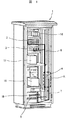
本発明の一実施例を図1から図6により詳細に説明する。図1は、本発明の一実施例である制御機器の内部実装を示す斜視図である。 An embodiment of the present invention will be described in detail with reference to FIGS. FIG. 1 is a perspective view showing the internal mounting of a control device according to an embodiment of the present invention.
制御機器1内の奥行き側には、上部側に電源変換機18,故障リレー回路2,制御装置3が取り付けられ、中段に無停電装置17,トランス16が取り付けられ、下部側に受電中継端子台19,筐体集合アース5が取り付けられている。外部からの受電用の受電中継端子台19から受電した電力は、トランス16,無停電装置17,電源変換機18,制御装置3の順に電気が流れるように接続されている。
On the depth side in the
側面の中央部から下部には外部インターフェース中継端子台4が設けられている。外部インターフェース中継端子台4と制御装置3,故障リレー回路2とは制御機器の内部配線6で接続されている。外部インターフェース中継端子台4は、制御機器の外部配線7により外部と接続されている。
An external interface
制御装置3では制御演算処理後に、制御機器1が制御する対象設備に制御信号を出力し、外部から必要な情報信号を入力する。一般的に外部からのサージは、制御機器の外部配線7を伝わって制御機器1内に侵入するので、制御機器1内の機器をサージから保護するため、外部インターフェース中継端子台4が制御機器1に実装されている。
The
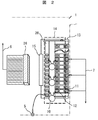
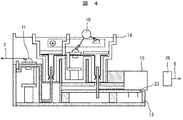
外部インターフェース中継端子台4は、図2から図4に示されるようにコネクタ構造となっている。図3に示すように、本実施例の外部インターフェース中継端子台4は、外部端子コネクタ14と本体13から構成されている。
The external interface
本体13には外部接点11が設けられ、外部接点11は内外部接点接続ピン22が設けられている。本体13の外部接点11とは反対側に内部配線用コネクタ15が取り付けられ、内部配線用コネクタ15はプリント板23と接続されている。プリント板23には内部回路25が設けられ、内部回路25は内部接点接続ピン24と接続されている。内部配線用コネクタ15には制御機器の内部配線6が設けられたコネクタ26をはめ込むことにより接続されるようになっている。
The
外部端子コネクタ14には内外部接点接続ピン21が、本体13の内外部接点接続ピン22と内部接点接続ピン24の位置に対応して2箇所設けられ、2箇所に設けられた内外部接点接続ピン21同士は接続されている。外部端子コネクタ14の内部接点接続ピン
24に対応する位置には内蔵アースバー20が設けられ、内外部接点接続ピン21に接続した内部接点12が設けられて内蔵アースバー20と内部接点12とにはバリスタ10が取り付けられる。
The
外部端子コネクタ14と本体13とは、図4に示すように、内外部接点接続ピン22と内部接点接続ピン24に内外部接点接続ピン21をはめ込むことにより結合される。内蔵アースバー20の端部は筐体集合アース5と接合できるようになっている。
As shown in FIG. 4, the
このように、本体13に設けられた外部端子の接点11と、外部端子コネクタ14に設けられた内部配線と取り外して分離できるようにし、分離して取り外すことができる外部端子コネクタ14にサージ対策品であるバリスタ10を取り付ける構造であるので、バリスタ10の取り付け,取り外しを制御機器の外部で作業できる。このため、制御機器内の狭いエリアでバリスタの一方の端部と内部配線6を重ねて内部接点12に取り付けるという従来の作業効率の悪さを改善できる。また、内部配線をコネクタ15,26により接続しているので、バラ配線から一括配線接続できる。また、外部端子コネクタを着脱することで、制御機器の外部配線と内部配線とを機械的,電気的に分離,結合できる。
In this way, the
外作業によりバリスタ10を取り付けた後、外部端子コネクタ14を制御機器1に取り付けられた本体13に挿入すると、両端下部の2つの内外部接点接続ピン21の一方が内部接点接続ピン24と接続され、プリント板23上の内部回路25を経由して内部配線用コネクタ15へ導通される。一方、外部端子コネクタ14の他方の内外部接点接続ピン
21が内外部接点接続ピン22と接続され、外部配線7に導通される。
After the
外部配線7から侵入してきたサージは、外部接点11,内部接点12を経由して静電対策あるいはサージ対策品であるバリスタ10に伝播し、バリスタ10で過電圧に対する保護が行われる。バリスタを経由したサージは、アースバー20により筐体集合アース5に逃がすことができる。このようにして、内部配線6にサージが伝わるのを防ぎ、制御機器1内部へのサージ侵入を防止できる。
The surge that has entered from the
また、図2に示す例では、外部配線7は3本接続されているが、これら3本の外部配線は、夫々別設備とのインターフェースであり、例えば設備Aのサージに対し設備A用のバリスタ10が損傷するが、損傷した設備のバリスタを保守時に交換することでよい。このように、プリント板の回路上にバリスタをハンダ接続している従来技術では、設備Aのサージによりプリント板回路の全てがショートするため、設備B,設備C分のバリスタも損傷してモジュール全部を交換することになるが、本実施例ではモジュール全部を交換することを避けることができる。また、取り外し可能な外部端子コネクタには、外部端子数と同数のバリスタ取り付け用の接点を設けているため、接点個々に静電、あるいはサージが発生して交換作業が必要となっても容易に交換できる。
In the example shown in FIG. 2, three
以上説明したように、本実施例によれば、制御装置からのバラ内部配線を一括してコネクタ接続できる。バリスタ取り付けは、制御機器内ではなく、制御機器の外で作業でき、一括して嵌め込むことができる。また、外部端子の接点別にサージをバリスタでカットし、交換もコネクタを分離して、バリスタ1つを交換して結合することで対応でき全交換しなくても良くなる。制御機器の組立・配線作業性の向上と、サージ保護に対し安価で容易に交換できる制御機器を実現できる。 As described above, according to the present embodiment, the loose internal wiring from the control device can be collectively connected to the connector. The varistor can be installed outside the control device, not inside the control device, and can be fitted together. In addition, surges can be cut with a varistor for each contact of the external terminal, and replacement can be performed by separating the connector and exchanging and connecting one varistor. It is possible to improve control device assembly and wiring workability, and to realize a control device that can be easily and inexpensively replaced for surge protection.
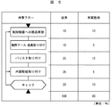
例えば、本実施例と従来技術との効果の比較を示す図5から分るように従来の作業工数を合計100%としたときに、本実施例では40%の取り付け作業工数となる。その内訳は、従来は専用アース・金具取り付けが10%であったのに対し、本実施例では0%、従来はバリスタ取り付けが25%であったのに対し、本実施例では15%、従来は内部配線取り付けが35%であったのに対し、本実施例では5%、従来はチェックが20%であったのに対し、本実施例では10%とそれぞれ低減されている。 For example, as can be seen from FIG. 5 showing a comparison of the effects of the present embodiment and the prior art, when the conventional work man-hour is 100% in total, in this embodiment, the attachment work man-hour is 40%. The breakdown is 10% for the dedicated earth and metal fittings in the past, 0% in the present example, and 25% for the varistor in the past. In the present embodiment, the internal wiring attachment was reduced to 35%, whereas in the present embodiment, it was reduced to 5%.
1…制御機器、2…故障リレー回路、3…制御装置、4…外部インターフェース中継端子台、5…筐体集合アース、6…内部配線、7…外部配線、10…バリスタ、11…外部接点、12…内部接点、13…本体、14…外部端子コネクタ、15…内部配線用コネクタ、16…トランス、17…無停電装置、18…電源変換機、19…受電中継端子台、
20…アースバー、21,22…内外部接点接続ピン、23…プリント板、24…内部接点接続ピン、25…内部回路、26…コネクタ。
DESCRIPTION OF
DESCRIPTION OF
Claims (4)
The control device according to claim 1, wherein the varistor is individually attached to the earth bar and an internal contact.
Priority Applications (1)
| Application Number | Priority Date | Filing Date | Title |
|---|---|---|---|
| JP2004109573A JP2005294130A (en) | 2004-04-02 | 2004-04-02 | Control equipment |
Applications Claiming Priority (1)
| Application Number | Priority Date | Filing Date | Title |
|---|---|---|---|
| JP2004109573A JP2005294130A (en) | 2004-04-02 | 2004-04-02 | Control equipment |
Publications (1)
| Publication Number | Publication Date |
|---|---|
| JP2005294130A true JP2005294130A (en) | 2005-10-20 |
Family
ID=35326817
Family Applications (1)
| Application Number | Title | Priority Date | Filing Date |
|---|---|---|---|
| JP2004109573A Pending JP2005294130A (en) | 2004-04-02 | 2004-04-02 | Control equipment |
Country Status (1)
| Country | Link |
|---|---|
| JP (1) | JP2005294130A (en) |
Cited By (2)
| Publication number | Priority date | Publication date | Assignee | Title |
|---|---|---|---|---|
| JP2015201988A (en) * | 2014-04-09 | 2015-11-12 | 株式会社安川電機 | Distribution system protection apparatus |
| JP6426798B1 (en) * | 2017-07-18 | 2018-11-21 | ファナック株式会社 | Reactor with terminal block |
-
2004
- 2004-04-02 JP JP2004109573A patent/JP2005294130A/en active Pending
Cited By (3)
| Publication number | Priority date | Publication date | Assignee | Title |
|---|---|---|---|---|
| JP2015201988A (en) * | 2014-04-09 | 2015-11-12 | 株式会社安川電機 | Distribution system protection apparatus |
| JP6426798B1 (en) * | 2017-07-18 | 2018-11-21 | ファナック株式会社 | Reactor with terminal block |
| US10438738B2 (en) | 2017-07-18 | 2019-10-08 | Fanuc Corporation | Reactor having terminal block |
Similar Documents
| Publication | Publication Date | Title |
|---|---|---|
| US7731508B2 (en) | Adapter board, socket, and device for connecting an electronic controller to the connection leads thereof | |
| CN107797053A (en) | The monitoring unit of observation circuit breaker and the breaker including the monitoring unit | |
| US6304188B1 (en) | Modular surge suppressor for a traffic cabinet | |
| US20130265731A1 (en) | Circuit board system | |
| CN109716597A (en) | Overvoltage protective module for modularization connectors | |
| US10497515B2 (en) | Connector structure | |
| JP2005294130A (en) | Control equipment | |
| CN102324646A (en) | Electric short-circuit connector | |
| KR102374082B1 (en) | housing | |
| KR200471607Y1 (en) | Surge Protect Device | |
| US6699076B2 (en) | Connector assembly with metal oxide varistor | |
| EP2319132B1 (en) | Multispur fieldbus barrier arrangement | |
| CN202940422U (en) | Circuit switching device and electronic machine cabinet using same | |
| EP1905056B2 (en) | Modular fieldbus segment protector | |
| KR20170077631A (en) | Assembling-dismantling type power supply apparatus | |
| RU2726645C2 (en) | Electronic device and processing of voltage surges | |
| CN208986219U (en) | Signal Connector Mounting Plates, Circuit Board Assemblies, Power Electronics Controllers and Vehicles | |
| KR101249382B1 (en) | Motor control center | |
| CN202142679U (en) | Short circuit electric connector | |
| EP2651200B1 (en) | Digital protective relay | |
| KR20180086017A (en) | Noise filter assembly mounted with surge protector | |
| CN221552811U (en) | Be used for full electronic interlocking to use guard cabinet fuse base device | |
| EP1879114A2 (en) | Separable transient voltage suppression device | |
| JP3126852U (en) | Line protector for communication circuit | |
| EP2581988A1 (en) | Adaptor and connection system |
Legal Events
| Date | Code | Title | Description |
|---|---|---|---|
| RD04 | Notification of resignation of power of attorney |
Effective date: 20060424 Free format text: JAPANESE INTERMEDIATE CODE: A7424 |
|
| A621 | Written request for application examination |
Free format text: JAPANESE INTERMEDIATE CODE: A621 Effective date: 20060620 |
|
| A977 | Report on retrieval |
Free format text: JAPANESE INTERMEDIATE CODE: A971007 Effective date: 20080627 |
|
| A131 | Notification of reasons for refusal |
Free format text: JAPANESE INTERMEDIATE CODE: A131 Effective date: 20080708 |
|
| A02 | Decision of refusal |
Free format text: JAPANESE INTERMEDIATE CODE: A02 Effective date: 20081111 |