JP2005294110A - Discharge lamp lighting device and socket cover used for discharge lamp lighting device - Google Patents
Discharge lamp lighting device and socket cover used for discharge lamp lighting device Download PDFInfo
- Publication number
- JP2005294110A JP2005294110A JP2004109073A JP2004109073A JP2005294110A JP 2005294110 A JP2005294110 A JP 2005294110A JP 2004109073 A JP2004109073 A JP 2004109073A JP 2004109073 A JP2004109073 A JP 2004109073A JP 2005294110 A JP2005294110 A JP 2005294110A
- Authority
- JP
- Japan
- Prior art keywords
- discharge lamp
- socket
- lighting device
- socket cover
- lamp lighting
- Prior art date
- Legal status (The legal status is an assumption and is not a legal conclusion. Google has not performed a legal analysis and makes no representation as to the accuracy of the status listed.)
- Withdrawn
Links
- 239000002184 metal Substances 0.000 claims description 22
- 230000005672 electromagnetic field Effects 0.000 abstract description 14
- 230000005855 radiation Effects 0.000 abstract description 13
- 230000004048 modification Effects 0.000 description 4
- 238000012986 modification Methods 0.000 description 4
- 230000001413 cellular effect Effects 0.000 description 2
- 238000000034 method Methods 0.000 description 2
- 239000007858 starting material Substances 0.000 description 1
- 230000009466 transformation Effects 0.000 description 1
Images



Landscapes
- Arrangement Of Elements, Cooling, Sealing, Or The Like Of Lighting Devices (AREA)
Abstract
Description
本発明は、自動車用前照灯点灯装置等に用いる放電灯点灯装置及び放電灯点灯装置に用いるソケットカバーに関するものである。 The present invention relates to a discharge lamp lighting device used for an automotive headlamp lighting device and the like, and a socket cover used for a discharge lamp lighting device.
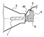
従来の放電灯点灯装置は、図6に示すように、放電灯点灯用インバータ回路(不図示)により点灯されるHID(High Intensity Discharge)バルブ等の放電灯1と、この放電灯1を組み込むための金属製の灯体2と、放電灯点灯用インバータ回路(不図示)から電力供給を受けて始動時に放電開始に必要な高圧パルスを放電灯1に印加する起動回路(不図示)を含むソケット部4と、このソケット部4の周囲を覆う金属製筐体のソケットカバー5と、灯体2の一部とソケットカバー5とを電気的に接続するための弾性を有する板状の金属製構造物60とを備えた構成であり、自動車用前照灯用に用いられるものを例示することができる。
As shown in FIG. 6, the conventional discharge lamp lighting device incorporates a
上述の放電灯点灯装置は、灯体2とソケットカバー5とを金属製構造物60にて接続させて、FM放送の周波数帯域を含むVHF帯域(30〜300MHz)の輻射ノイズレベルを低減させることで、バルブ放電を原因とする迷走電流(コモンモード電流)を抑制して、バルブから放射されラジオ受信機等の車載機器に対して影響を与えるコモンモード放射電磁界を低減させている(例えば特許文献1、図6参照)。
ところが、上述のような従来の放電灯点灯装置においては、弾性を有する板状の金属製構造物を別途設けて、灯体とソケットカバーとを接続してコモンモード放射電磁界の低減をはかっているため、部品点数が増加することで、放電灯点灯装置自体のコストアップにつながる可能性があった。また、放電灯点灯装置は、組み立て時やバルブの交換を想定すると、灯体とソケットカバーとが着脱自在であるため、灯体とソケットカバーとの電気的接続を更に安定化して行う必要があった。 However, in the conventional discharge lamp lighting device as described above, an elastic plate-like metal structure is separately provided, and the lamp body and the socket cover are connected to reduce the common mode radiation electromagnetic field. Therefore, an increase in the number of parts may lead to an increase in the cost of the discharge lamp lighting device itself. In addition, since the lamp and the socket cover are detachable when the discharge lamp lighting device is assumed to be assembled or the bulb is replaced, it is necessary to further stabilize the electrical connection between the lamp and the socket cover. It was.
本発明は、上記従来技術の問題に鑑み、コモンモード放射電磁界低減のための灯体とソケットカバーとの電気的接続をシンプルな機構で安定して実現する放電灯点灯装置及びソケットカバーを提供することを目的とする。 The present invention provides a discharge lamp lighting device and a socket cover that stably realizes an electrical connection between a lamp body and a socket cover for reducing a common mode radiated electromagnetic field with a simple mechanism in view of the above-described problems of the prior art. The purpose is to do.
上述の目的を達成するために、本発明の請求項1に係る放電灯点灯装置は、放電灯点灯用インバータ回路により点灯される放電灯と、該放電灯を装着するためのソケット部と、該ソケット部の周囲を覆う金属製のソケットカバーと、前記ソケット部への対向面に対向部を有し、前記放電灯を組み込む金属製の灯体とを備えた放電灯点灯装置であって、前記ソケットカバーと前記灯体との間に、一端が前記ソケットカバーに電気的に接続され、他端が前記ソケット部側から前記対向部に電気的接続可能な弾性を有する接続部を、前記対向部の全周囲にわたり複数個設けている。
In order to achieve the above-mentioned object, a discharge lamp lighting device according to
また、本発明の請求項2に係る放電灯点灯装置は、放電灯点灯用インバータ回路により点灯される放電灯と、該放電灯を装着するためのソケット部と、該ソケット部の周囲を覆う金属製のソケットカバーと、前記ソケット部への対向面に対向部を有し、前記放電灯を組み込む金属製の灯体とを備えた放電灯点灯装置であって、前記ソケットカバーと前記灯体との間に、一端が前記ソケットカバーに電気的に接続され、他端が前記ソケット部側から前記対向部に電気的接続可能な弾性を有する接続部を、前記対向部の全周囲にわたり連続して設けている。 According to a second aspect of the present invention, there is provided a discharge lamp lighting device comprising: a discharge lamp that is lit by a discharge lamp lighting inverter circuit; a socket portion for mounting the discharge lamp; and a metal that covers the periphery of the socket portion. A discharge lamp lighting device comprising: a socket cover made of metal; and a metal lamp body having a facing portion on a surface facing the socket section and incorporating the discharge lamp, wherein the socket cover and the lamp body During this, one end is electrically connected to the socket cover, and the other end is continuously connected over the entire periphery of the facing portion with elasticity that can be electrically connected from the socket side to the facing portion. Provided.
また、本発明の請求項3に係る放電灯点灯装置は、請求項1又は請求項2に記載の放電灯点灯装置において、前記接続部が前記ソケットカバーと一体形成されている。 According to a third aspect of the present invention, in the discharge lamp lighting device according to the first or second aspect, the connecting portion is integrally formed with the socket cover.
また、本発明の請求項4に係る放電灯点灯装置は、請求項1又は請求項2に記載の放電灯点灯装置において、前記接続部が前記ソケットカバーと別途形成されている。
According to
また、本発明の請求項5に係る放電灯点灯装置は、請求項1乃至請求項4のいずれかに記載の放電灯点灯装置において、前記放電灯は、バルブ本体と、バルブ電極と、前記バルブ本体と前記バルブ電極との間に設けたバルブマウントとを少なくとも備え、前記灯体は、該灯体と前記ソケット部との間で前記バルブマウントを挟持するストッパー部を備えるとともに、前記接続部と着脱自在に嵌合する嵌合接続部を備えている。 A discharge lamp lighting device according to a fifth aspect of the present invention is the discharge lamp lighting device according to any one of the first to fourth aspects, wherein the discharge lamp includes a bulb body, a bulb electrode, and the bulb. At least a bulb mount provided between the main body and the bulb electrode, and the lamp body includes a stopper portion for sandwiching the bulb mount between the lamp body and the socket portion, and the connection portion. It has a fitting connection part that is detachably fitted.
また、本発明の請求項6に係る放電灯点灯装置に用いるソケットカバーは、放電灯点灯用インバータ回路により点灯される放電灯と、前記放電灯を装着するためのソケット部と、該ソケット部の周囲を覆う金属製のソケットカバーと、前記ソケット部への対向面に対向部を有し、前記放電灯を組み込む金属製の灯体とを備えた放電灯点灯装置に用いるソケットカバーであって、前記ソケットカバーは、前記ソケット部側から前記対向部の全周囲にわたり電気的接続可能な弾性を有する接続部を備えている。
A socket cover used in the discharge lamp lighting device according to
このような構成の放電灯点灯装置は、ソケットカバーと灯体との間に、一端がソケットカバーに電気的に接続され、他端が灯体側の対向部に電気的接続可能な弾性を有する接続部を対向部の全周囲、つまり360度にわたり複数個設け、灯体とソケットカバーとを電気的に低いインピーダンスで接続することで、コモンモード放射電磁界低減をシンプルな機構で安定して実現することができる。 In the discharge lamp lighting device having such a configuration, between the socket cover and the lamp body, one end is electrically connected to the socket cover, and the other end is an elastic connection that can be electrically connected to the facing portion on the lamp body side. A common mode radiated electromagnetic field reduction can be realized stably with a simple mechanism by providing a plurality of parts over the entire circumference of the opposing part, that is, 360 degrees, and connecting the lamp body and the socket cover with an electrically low impedance. be able to.
また、このような構成の放電灯点灯装置は、ソケットカバーと灯体との間に、一端がソケットカバーに電気的に接続され、他端が灯体側の対向部に電気的接続可能な弾性を有する接続部を対向部の全周囲、つまり360度にわたり連続して設け、灯体とソケットカバーとを電気的に低いインピーダンスで接続することで、コモンモード放射電磁界低減をシンプルな機構で安定して実現することができる。 In addition, the discharge lamp lighting device having such a configuration has elasticity that allows one end to be electrically connected to the socket cover and the other end to be electrically connected to the facing portion on the lamp body between the socket cover and the lamp body. The connection part is provided continuously over the entire circumference of the opposite part, that is, 360 degrees, and the lamp and socket cover are electrically connected with low impedance, so that the common mode radiation electromagnetic field can be reduced with a simple mechanism. Can be realized.
また、このような構成の放電灯点灯装置に用いるソケットカバーは、ソケットカバーに対してソケット部側から灯体側の対向部の全周囲にわたり電気的接続可能な弾性を有する接続部を設けることで、様々な灯体に対して汎用的にコモンモード放射電磁界を低減させることができる。 Further, the socket cover used for the discharge lamp lighting device having such a configuration is provided with a connecting portion having elasticity that can be electrically connected to the socket cover over the entire periphery of the facing portion on the lamp body side from the socket portion side. The common mode radiation electromagnetic field can be reduced for various lamps in general.
以下、本発明に係る実施形態を図面に基づいて説明する。なお、各図において、同一の符号を付した構成は、同一の構成であることを示し、その説明を省略する。 Embodiments according to the present invention will be described below with reference to the drawings. In addition, in each figure, the structure which attached | subjected the same code | symbol shows that it is the same structure, The description is abbreviate | omitted.
(第1実施形態)
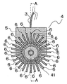
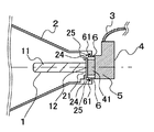
本発明の第1実施形態を図1及び図2に基づいて説明する。図1は、本発明の第1実施形態に係る放電灯点灯装置の要部構成を示す側部断面図であり、図2は、ソケット部、ソケットカバーを示す正面図(灯体側から見た正面図)である。なお、図1は、図2におけるA−A断面での側部の断面図を示したものである。
(First embodiment)
1st Embodiment of this invention is described based on FIG.1 and FIG.2. FIG. 1 is a side sectional view showing a main part configuration of a discharge lamp lighting device according to a first embodiment of the present invention, and FIG. 2 is a front view showing a socket part and a socket cover (front view seen from the lamp body side). Figure). FIG. 1 is a cross-sectional view of a side portion taken along the line AA in FIG.
本実施形態においては、放電灯点灯装置は、自動車用前照灯用に用いられ、図1に示すように、放電灯点灯用インバータ回路(不図示)により点灯される放電灯1であるHIDバルブと、この放電灯1を1組み込むための金属製の灯体2と、放電灯点灯用インバータ回路から例えばシールドメッシュで被覆されたイグナイタハーネス3を介して電力供給を受けて始動時に放電開始に必要な高圧パルスを放電灯1に印加する起動回路(不図示)を含むソケット部4と、このソケット部4の周囲を覆う金属製筐体のソケットカバー5と、後述する接続部6を備えた構成である。なお、放電灯1であるHIDバルブは、バルブ本体11と、バルブ電極(不図示)と、バルブ本体11とバルブ電極との間に形成されたバルブマウント12とを少なくとも備えている。
In the present embodiment, the discharge lamp lighting device is used for an automotive headlamp, and as shown in FIG. 1, an HID bulb that is a
ここで、灯体2は、ソケット部4と対向する側に設けた開口部21と、開口部21の周囲を取り囲む対向部22とを備えており、放電灯1のバルブ電極は、この開口部21を通ってソケット部4に設けた電極コネクタ部41と例えば嵌合するなどして電気的に接続して装着される。
Here, the
本実施形態においては、ソケットカバー5は、図1及び図2に示すように、ソケットカバー5と一体に形成された弾性を有した金属製の複数個の接続部6を備えた構成である。なお、これら各接続部6の一端は、灯体2に設けた対向部22の全周囲にわたり、つまり、360度にわたり等間隔に(例えば28個)自身の弾性により、灯体2に圧接可能であり、灯体2とソケットカバー5とが電気的に接続された構成となっている。接続部6の断面形状は、例えば、レ字状の形状である。
In this embodiment, as shown in FIGS. 1 and 2, the
なお、灯体2とソケットカバー5との固定方法は、ソケットカバー5を対向部22に圧接させて両者を電気的に接続させることができる方法であればどのような方法であってもよい。一例としては、図1に示すように、灯体2の対向部22にマウント12を搭載するマウント搭載部23を設け、灯体2にバルブマウント12を固定し、灯体2のバルブ電極をソケット部4に設けた嵌合箇所である電極コネクタ部41に嵌合して、灯体2とソケットカバー5とを固定する。
The fixing method of the
なお、本実施形態では、ソケットカバー5に放射状に形成された28個の接続部6を一体形成しているが、接続部6の個数は、コモンモード放射電磁界低減のためには、対向部22全周囲360度にわたって各々の接続部6が重ならない範囲で最大個数にし、最大幅を採用することが好ましい。また、接続部6に弾性を持たせることで、灯体2への接圧を十分に持たせることができる。
In the present embodiment, 28
本実施形態に係る放電灯点灯装置は、ソケットカバー5に一体形成した接続部6の先端が灯体2に設けた対向部22の全周囲、つまり360度にわたって灯体2に電気的に接続して連続的にシールドし、灯体2とソケットカバー5とを電気的に低いインピーダンスで接続することで、バルブの放電現象に起因する高周波ノイズ電流が灯体2を介してソケットカバー5及びイグナイタハーネス3を流れ放電灯点灯用インバータ回路まで最短距離で帰還する。つまり、接続部6により、前述のように最短距離で帰還できずに放射の主要因となる迷走電流(コモンモード電流)を抑制することができるので、コモンモード放射電磁界低減をシンプルな機構で安定して実現することができる。
In the discharge lamp lighting device according to the present embodiment, the tip of the
また、上述のようにソケットカバー5と接続部6とを一体化した構成とすることで、ソケット部4と対向する側に対向部22を有する金属製の灯体2に対して汎用的にコモンモード放射電磁界低減対策が可能となる。なお、本実施形態に係る放電灯点灯装置では、VHF帯域(30〜300MHz)以上、例えば1000MHzを超えた携帯電話、無線LAN等の使用帯域である高周波数帯域であっても輻射ノイズレベルを低減させることができる。
Further, as described above, the
ここで、本実施形態の変形形態としては、図略するが、接続部(不図示)をソケットカバー5とは別途形成した構成の放電灯点灯装置を挙げることができる。ソケット部4とソケットカバー5との間に所定の空間(以降、被挟空間と称する。)を有するような場合に、接続部は、被挟空間に被挟させ固定するための被挟部(不図示)と、灯体2に設けた対向部22と電気的接続を行う先端部(不図示)とを備えた弾性を有した金属製の部材である。変形形態の放電灯点灯装置においては、このような接続部が、灯体2に設けた対向部22全周囲、つまり360度にわたって灯体2とソケットカバー5とを電気的に接続して連続的にシールドするように設けられた構成である。
Here, as a modification of the present embodiment, although not shown, a discharge lamp lighting device having a configuration in which a connection portion (not shown) is formed separately from the
本変形形態に係る放電灯点灯装置においても、本実施形態(第1実施形態)と同様に、コモンモード放射電磁界低減をシンプルな機構で安定して実現することができる。また、既存のソケット部4とソケットカバー5とが被挟空間を有する場合に、部品点数が増加するものの、ソケットカバー5とは別途形成した接続部によって、ソケット部4と対向する側に対向部22を有する金属製の灯体2に対して、汎用的にかつ安定したコモンモード放射電磁界低減対策が可能となる。
Also in the discharge lamp lighting device according to the present modification, common mode radiation electromagnetic field reduction can be stably realized with a simple mechanism, as in the present embodiment (first embodiment). Further, when the existing
(第2実施形態)
次に、他の実施形態を、本発明の第2実施形態として図3乃至図5に基づいて説明する。図3は、本発明の第2実施形態に係る放電灯点灯装置の要部構成を示す側部断面図であり、図4は、ソケット部、ソケットカバーを示す正面図(灯体側から見た正面図)である。図5は、ソケット部、ソケットカバーの変形形態を示す正面図(灯体側から見た正面図)である。なお、図3は、図4、図5におけるB−B断面での側部の断面図を示したものである。
(Second Embodiment)
Next, another embodiment will be described based on FIGS. 3 to 5 as a second embodiment of the present invention. FIG. 3 is a side sectional view showing a main part configuration of a discharge lamp lighting device according to a second embodiment of the present invention, and FIG. 4 is a front view showing a socket part and a socket cover (front view seen from the lamp body side). Figure). FIG. 5 is a front view (a front view seen from the lamp body side) showing a modified form of the socket part and the socket cover. FIG. 3 is a cross-sectional view of a side portion taken along the line BB in FIGS. 4 and 5.
本実施形態において、接続部6は、図3に示すように、第1実施形態と同様にソケットカバー5と複数個、例えば16個の接続部6とが一体化されるともに、図4に示すように、その先端には、嵌合用の先端部61であるかえし(凸部)を備えた構成である。複数個の接続部6は、対向部22全周囲360度にわたって各々の接続部6が重ならない範囲で最大個数にし、最大幅を採用することが好ましい。
In the present embodiment, as shown in FIG. 3, the
また、灯体2は、灯体2とソケット部4との間でバルブマウント12を挟持するストッパー部24と、ストッパー部24とソケットカバー5との間に、対向部22を含む構成にて形成された嵌合接続部25である凹部とを備えている。
In addition, the
本実施形態に係る放電灯点灯装置は、灯体2に設けた対向部22の全周囲、つまり360度にわたって灯体2とソケットカバー5とを電気的に接続し連続的にシールドする接続部6を設け、灯体2とソケットカバー5とを電気的に低いインピーダンスで接続することで、コモンモード放射電磁界低減をシンプルな機構で安定して実現することができる。また、灯体2がストッパー部24と上述の嵌合接続部25とを備え、ソケットカバー5には灯体2の嵌合接続部25と電気的接続して嵌合可能な先端部61を設けることで、放電灯1、灯体2、ソケット部4の組み立てが極めて簡素化できる。なお、本実施形態に係る放電灯点灯装置では、VHF帯域(30〜300MHz)以上、例えば1000MHzを超える携帯電話、無線LAN等の使用帯域である高周波数帯域であっても輻射ノイズレベルを低減させることができる。
In the discharge lamp lighting device according to the present embodiment, the
なお、本実施形態において、灯体2とソケットカバー5との電気的接続は、接続部6に設けた先端部61である凸部と灯体2に設けた嵌合接続部25である凹部で、灯体2と接続部6各々を嵌合しているが、先端部61に凹部を設け、嵌合接続部25に凸部を設けて、灯体2と接続部6各々を電気的に接続するような構成であってもよい。ここで、先端部61と嵌合接続部25との形状は、お互いが着脱自在に嵌合可能な形状であれば特に凹部、凸部の形状に限ったものではない。また、接続部6は、ソケットカバー5と一体形成せずに、別途形成して後両者を一体化してもよい。
In the present embodiment, the electrical connection between the
ここで、本実施形態の変形形態としては、図5に示すように、接続部6は、リング状の連続した筒に先端部61であるかえし(例えば、リング状の凸部)を備えた構成であってもよい。この場合、放電灯点灯装置の要部構成を示す側部断面図は図略するが、灯体2に設けた嵌合接続部(例えば凹部)は、接続部6の先端部61と電気的に接続してかつ嵌合可能なリング状に形成されている。なお、接続部6は、ソケットカバー5と一体形成されていても、別途形成して後に一体化してもよい。図5に示すように、このようなリング状の接続部6は、灯体2に設けた対向部22の全周囲、つまり360度にわたって灯体2とソケットカバー5とを電気的に接続し連続的にシールドすることができる。
Here, as a modification of the present embodiment, as shown in FIG. 5, the connecting
本変形形態に係る放電灯点灯装置においても、本実施形態(第2実施形態)と同様に、コモンモード放射電磁界低減をシンプルな機構で安定して実現することができる。 Also in the discharge lamp lighting device according to the present modification, common mode radiation electromagnetic field reduction can be stably realized with a simple mechanism, as in the present embodiment (second embodiment).
ここで、第1実施形態及び第2実施形態においては、放電灯点灯装置の放電灯1は、自動車用前照灯用に用いられるHIDバルブであるが、自動車用の前照灯用に限ったものではなく、インバータ式の放電灯であればどのような用途の放電灯であってもよい。
Here, in the first embodiment and the second embodiment, the
1 放電灯
2 灯体
3 イグナイタハーネス
4 ソケット部
5 ソケットカバー
6 接続部
11 バルブ本体
12 マウント
21 開口部
22 対向部
23 マウント搭載部
24 ストッパー部
25 嵌合接続部
41 電極コネクタ部
61 先端部
DESCRIPTION OF
Claims (6)
前記ソケットカバーと前記灯体との間に、一端が前記ソケットカバーに電気的に接続され、他端が前記ソケット部側から前記対向部に電気的接続可能な弾性を有する接続部を、前記対向部の全周囲にわたり複数個設けたことを特徴とする放電灯点灯装置。 A discharge lamp that is lit by an inverter circuit for lighting a discharge lamp, a socket portion for mounting the discharge lamp, a metal socket cover that covers the periphery of the socket portion, and a facing portion on a surface facing the socket portion A discharge lamp lighting device comprising a metal lamp body incorporating the discharge lamp,
Between the socket cover and the lamp body, one end is electrically connected to the socket cover, and the other end has an elastic connecting portion that can be electrically connected from the socket portion side to the facing portion. A discharge lamp lighting device characterized in that a plurality of lamps are provided over the entire circumference of the part.
前記ソケットカバーと前記灯体との間に、一端が前記ソケットカバーに電気的に接続され、他端が前記ソケット部側から前記対向部に電気的接続可能な弾性を有する接続部を、前記対向部の全周囲にわたり連続して設けたことを特徴とする放電灯点灯装置。 A discharge lamp that is lit by an inverter circuit for lighting a discharge lamp, a socket portion for mounting the discharge lamp, a metal socket cover that covers the periphery of the socket portion, and a facing portion on a surface facing the socket portion A discharge lamp lighting device comprising a metal lamp body incorporating the discharge lamp,
Between the socket cover and the lamp body, one end is electrically connected to the socket cover, and the other end has an elastic connecting portion that can be electrically connected from the socket portion side to the facing portion. A discharge lamp lighting device characterized by being continuously provided over the entire circumference of the section.
前記灯体は、該灯体と前記ソケット部との間で前記バルブマウントを挟持するストッパー部を備えるとともに、前記接続部と着脱自在に嵌合する嵌合接続部を備えた請求項1乃至請求項4のいずれかに記載の放電灯点灯装置。 The discharge lamp includes at least a bulb body, a bulb electrode, and a bulb mount provided between the bulb body and the bulb electrode,
The said lamp body is provided with the stopper connection part which clamps the said valve mount between this lamp body and the said socket part, and was provided with the fitting connection part detachably fitted with the said connection part. Item 5. A discharge lamp lighting device according to any one of Items 4 to 7.
前記ソケットカバーは、前記ソケット部側から前記対向部の全周囲にわたり電気的接続可能な弾性を有する接続部を備えたことを特徴とする放電灯点灯装置に用いるソケットカバー。 A discharge lamp that is lit by an inverter circuit for lighting a discharge lamp, a socket portion for mounting the discharge lamp, a metal socket cover that covers the periphery of the socket portion, and a facing portion on a surface facing the socket portion A socket cover for use in a discharge lamp lighting device comprising a metal lamp incorporating the discharge lamp,
The socket cover includes a connecting portion having elasticity that can be electrically connected from the socket portion side to the entire periphery of the facing portion. The socket cover is used for a discharge lamp lighting device.
Priority Applications (1)
| Application Number | Priority Date | Filing Date | Title |
|---|---|---|---|
| JP2004109073A JP2005294110A (en) | 2004-04-01 | 2004-04-01 | Discharge lamp lighting device and socket cover used for discharge lamp lighting device |
Applications Claiming Priority (1)
| Application Number | Priority Date | Filing Date | Title |
|---|---|---|---|
| JP2004109073A JP2005294110A (en) | 2004-04-01 | 2004-04-01 | Discharge lamp lighting device and socket cover used for discharge lamp lighting device |
Publications (1)
| Publication Number | Publication Date |
|---|---|
| JP2005294110A true JP2005294110A (en) | 2005-10-20 |
Family
ID=35326801
Family Applications (1)
| Application Number | Title | Priority Date | Filing Date |
|---|---|---|---|
| JP2004109073A Withdrawn JP2005294110A (en) | 2004-04-01 | 2004-04-01 | Discharge lamp lighting device and socket cover used for discharge lamp lighting device |
Country Status (1)
| Country | Link |
|---|---|
| JP (1) | JP2005294110A (en) |
Cited By (1)
| Publication number | Priority date | Publication date | Assignee | Title |
|---|---|---|---|---|
| WO2010112289A1 (en) * | 2009-03-30 | 2010-10-07 | Osram Gesellschaft mit beschränkter Haftung | High-pressure discharge lamp |
-
2004
- 2004-04-01 JP JP2004109073A patent/JP2005294110A/en not_active Withdrawn
Cited By (4)
| Publication number | Priority date | Publication date | Assignee | Title |
|---|---|---|---|---|
| WO2010112289A1 (en) * | 2009-03-30 | 2010-10-07 | Osram Gesellschaft mit beschränkter Haftung | High-pressure discharge lamp |
| CN102379022A (en) * | 2009-03-30 | 2012-03-14 | 奥斯兰姆有限公司 | High-pressure discharge lamp |
| US8491177B2 (en) | 2009-03-30 | 2013-07-23 | Osram Gesellschaft Mit Beschrankter Haftung | High-pressure discharge lamp |
| CN102379022B (en) * | 2009-03-30 | 2014-08-27 | 奥斯兰姆有限公司 | High-pressure discharge lamp |
Similar Documents
| Publication | Publication Date | Title |
|---|---|---|
| KR100272902B1 (en) | Vehicular lamp having discharge bulb | |
| US6309089B1 (en) | Vehicle lamp with discharge bulb, electrically-conductive cover, and reflector having electrically-conductive film on reflector surface | |
| BR0302310A (en) | Apparatus and method of annular antenna and transceiver arrangement in tires | |
| JPH1074404A (en) | High pressure discharge lamp device | |
| JP6211326B2 (en) | Light source device and vehicle lamp | |
| US7993044B2 (en) | Vehicle lighting apparatus | |
| KR100298517B1 (en) | Illumination mounted antenna | |
| JP5409893B2 (en) | High pressure discharge lamp | |
| DE502004005758D1 (en) | VEHICLE MOBILE SUPPORT | |
| JP5047843B2 (en) | Aircraft exterior lighting | |
| US5906428A (en) | Vehicle lamp with discharge bulb | |
| TWI492454B (en) | Mobile device and manufacturing method thereof | |
| JP6045246B2 (en) | Light source lighting device | |
| JP3162300B2 (en) | Vehicle lamp having a discharge bulb | |
| JP3854349B2 (en) | Vehicle lamp having a discharge bulb | |
| KR200455463Y1 (en) | HID lamps with separate ignition assembly | |
| JPH0745129A (en) | Ignition code | |
| KR20150093513A (en) | Head lamp module | |
| CN205690322U (en) | A kind of LED down | |
| US6670764B2 (en) | Discharge lamp unit with noise shields and noise control method for discharge lamp unit | |
| JP2000173311A (en) | Vehicle headlights | |
| JP2003223804A (en) | Vehicle headlights | |
| JP4508154B2 (en) | Automotive discharge lamp headlamp | |
| JP3854334B2 (en) | Vehicle lamp having a discharge bulb | |
| JP4296846B2 (en) | Discharge lamp starting device and discharge lamp lighting device |
Legal Events
| Date | Code | Title | Description |
|---|---|---|---|
| A621 | Written request for application examination |
Free format text: JAPANESE INTERMEDIATE CODE: A621 Effective date: 20070117 |
|
| A761 | Written withdrawal of application |
Free format text: JAPANESE INTERMEDIATE CODE: A761 Effective date: 20090212 |