JP2005294050A - lighting equipment - Google Patents
lighting equipment Download PDFInfo
- Publication number
- JP2005294050A JP2005294050A JP2004107793A JP2004107793A JP2005294050A JP 2005294050 A JP2005294050 A JP 2005294050A JP 2004107793 A JP2004107793 A JP 2004107793A JP 2004107793 A JP2004107793 A JP 2004107793A JP 2005294050 A JP2005294050 A JP 2005294050A
- Authority
- JP
- Japan
- Prior art keywords
- lamp
- lighting
- illuminance
- phosphorescent paint
- fixture
- Prior art date
- Legal status (The legal status is an assumption and is not a legal conclusion. Google has not performed a legal analysis and makes no representation as to the accuracy of the status listed.)
- Pending
Links
- 239000003973 paint Substances 0.000 claims abstract description 20
- 230000002093 peripheral effect Effects 0.000 claims abstract description 13
- 230000000694 effects Effects 0.000 description 5
- 230000008033 biological extinction Effects 0.000 description 1
- 230000003760 hair shine Effects 0.000 description 1
- 230000001771 impaired effect Effects 0.000 description 1
- 239000002184 metal Substances 0.000 description 1
Images


Landscapes
- Non-Portable Lighting Devices Or Systems Thereof (AREA)
Abstract
【課題】 高出力ランプを使用しなくても点灯時の照度が低くならないようにする。
【構成】 照明器具は、屋内の天井A等に取り付けられる埋め込み型のもので、器具本体10と、器具本体10の中心部に配設されたランプ30とを有し、器具本体10のランプ前方に位置する周縁部分121に蓄光塗料40が塗布されている。そのため、消灯後に光って適度な照度を得ることができる。また、器具本体10の周縁部分121については、ランプ30から出力された光の反射に大きな影響を及ぼさない部分であることから、高出力ランプを使用しなくても点灯時の照度が低くならない。
【選択図】 図4PROBLEM TO BE SOLVED: To prevent illuminance at lighting from being lowered without using a high-power lamp.
[Configuration] The lighting fixture is an embedded type that can be attached to an indoor ceiling A or the like, and includes a fixture main body 10 and a lamp 30 disposed in the center of the fixture main body 10. The phosphorescent paint 40 is applied to the peripheral portion 121 located at the position. For this reason, it is possible to obtain an appropriate illuminance after being turned off. Further, since the peripheral portion 121 of the instrument main body 10 is a portion that does not significantly affect the reflection of the light output from the lamp 30, the illuminance at the time of lighting does not decrease even if a high-power lamp is not used.
[Selection] Figure 4
Description
本発明は光源からの光が照射される部位に蓄光塗料が施されて消灯後も適度な照度を得ることが可能な照明器具に関する。 The present invention relates to a luminaire capable of obtaining an appropriate illuminance even after extinction by applying a phosphorescent paint to a portion irradiated with light from a light source.
この種の照明器具の従来例として、蓄光塗料を施こした箇所が半透明カバーであるもの( これを第1の従来例とする。例えば、特許文献1等参照) 、反射板であるもの( これを第2の従来例とする。例えば、特許文献2等参照) がある。
しかしながら、第1の従来例による場合、光源が半透明カバーで覆われていることから、点灯時の照度が低くなるという欠点がある。一方、第2の従来例による場合、蓄光塗料が反射板の表面全体に施されていることから、その反射効果が極端に低下し、点灯時の照度が同様に低くなるという欠点がある。このような欠点はいずれも高出力ランプを使用することにより是正されるものの、これに伴ってコスト高になるのは明らかである。 However, according to the first conventional example, since the light source is covered with the semi-transparent cover, there is a drawback that the illuminance at the time of lighting becomes low. On the other hand, in the case of the second conventional example, since the phosphorescent paint is applied to the entire surface of the reflecting plate, there is a disadvantage that the reflection effect is extremely lowered and the illuminance at the time of lighting is similarly lowered. Although all of these disadvantages are corrected by using high power lamps, it is clear that the cost increases accordingly.
本発明は上記した背景の下で創作されたものであって、その目的とするところは、高出力ランプを使用しなくても点灯時の照度が低くならないようにした照明器具を提供することにある。 The present invention was created under the above-mentioned background, and the object of the present invention is to provide a luminaire in which the illuminance at the time of lighting is not lowered even if a high-power lamp is not used. is there.
本発明の照明器具はランプとは異なる別部品のランプ前方に位置する部分に蓄光塗料が塗布されている。例えば、反射板の奥側中心位置にランプが配置された照明器具の場合、反射板の前方周縁部分に蓄光塗料を塗布するようにすると良い。 In the luminaire of the present invention, a phosphorescent paint is applied to a part located in front of the lamp, which is a separate part different from the lamp. For example, in the case of a luminaire in which a lamp is arranged at the center position on the back side of the reflecting plate, the phosphorescent paint may be applied to the front peripheral portion of the reflecting plate.
本発明の請求項1に係る照明器具による場合、ランプとは異なる別部品のランプ前方に位置する部分に蓄光塗料が塗布された構成となっているで、その部分が消灯後に光って適度な照度を得ることができ、消灯後や停電時の安全性を高めることができる。また、蓄光塗料が塗布された部分がランプ前方位置であることから、反射板の反射効果に大きな影響を及ぼさない。即ち、高出力ランプを使用しなくても点灯時の照度が低くならず、低コスト化を図る上で大きなメリットがある。 In the case of the luminaire according to claim 1 of the present invention, the phosphorescent paint is applied to a portion located in front of the lamp, which is a separate part different from the lamp, and the portion shines after being extinguished and has an appropriate illuminance. It is possible to improve safety after turning off the light or during a power failure. In addition, since the portion where the phosphorescent paint is applied is the front position of the lamp, the reflection effect of the reflector is not greatly affected. That is, even when a high output lamp is not used, the illuminance at the time of lighting is not lowered, and there is a great merit in reducing the cost.
本発明の請求項2に係る照明器具による場合、反射板の前方周縁部分に蓄光塗料を塗布された構成となっているので、請求項1の効果に加えて、次のような効果がある。即ち、反射板の前方周縁部分については、人目に触れる部分でデザイン化されていることが多く、その部分がランプに遮られることなく消灯後にそのままの形状で光って強調されることから、この点での商品価値も高まる。 In the case of the lighting fixture according to claim 2 of the present invention, since the phosphorescent paint is applied to the front peripheral portion of the reflector, the following effect is obtained in addition to the effect of claim 1. In other words, the front peripheral part of the reflector is often designed at the part that touches the human eye, and this part is emphasized by shining in the same shape after being extinguished without being blocked by the lamp. The product value at will also increase.
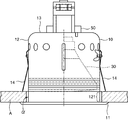
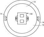
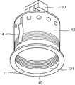
以下、本発明の第1の実施の形態を図面を参照して説明する。図1は第1の実施の形態に係る照明器具の側面図、図2は同器具の正面図、図3は同器具の背面図、図4は同器具の斜視図である。 Hereinafter, a first embodiment of the present invention will be described with reference to the drawings. 1 is a side view of the lighting apparatus according to the first embodiment, FIG. 2 is a front view of the apparatus, FIG. 3 is a rear view of the apparatus, and FIG. 4 is a perspective view of the apparatus.
ここに掲げる照明器具は屋内の天井A等に取り付けられる埋め込み型のもので、円筒状の器具本体10と、器具本体10内の中心部に配設されたランプ30とを有した基本構成となっている。同器具において最も特徴的であるのは、器具本体10のランプ前方に位置する周縁部分121に蓄光塗料40が塗布されている点である。以下、各部を詳細に検討する。
The lighting fixture listed here is an embedded type that can be attached to an indoor ceiling A or the like, and has a basic configuration including a
器具本体10については、ここでは有底円筒状の金属製のものを用いており、ランプ30の反射板も兼ねている。これは、円筒部12と、円筒部12の前方に位置する環状のフランジ部11と、円筒部12の後方に位置する円板状の支持板13と、円筒部12の外面にネジ止めされた板バネである一対の取付バネ14とを有した構造となっている。
The
円筒部12の前方部分には図4に示すように複数の段差が形成されており、その前方の平らな部分(周縁部分121)に蓄光塗料40が塗布されている。支持板12には連結送り端子付きソケット50がネジ止めされている。支持板12の面上には図示されていないが、ソケット50のランプ接続金具を露出させるための開口が形成されている。
As shown in FIG. 4, a plurality of steps are formed in the front portion of the
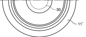
ランプ30については、ここでは白熱電球を用いており、上記したソケット50のランプ接続金具に着脱可能になっている。ソケット50に取り付けられた状態のランプ30は、器具本体10の奥側中心であり且つ器具本体10の周縁部分121の奥側に位置するようになっている。
Here, an incandescent lamp is used for the
このように構成された照明器具は、図1に示すように天井Aに形成された埋込穴αに挿入されると、取付バネ14の先端部分が天井Aの裏側に当接し、これで天井Aに取り付けられるようになっている。そして、器具本体10の周縁部分121に蓄光塗料40が塗布されていることから、その部分が消灯後に光って適度な照度を得ることができ、消灯後や停電時の安全性を高めることが可能になる。
When the lighting fixture thus configured is inserted into the embedding hole α formed in the ceiling A as shown in FIG. 1, the tip of the
また、器具本体10の周縁部分121については、ランプ30から出力された光の反射に大きな影響を及ぼさない部分であることから、高出力ランプを使用しなくても点灯時の照度が低くならず、低コスト化を図る上で大きなメリットがある。
Further, since the
さらに、蓄光塗料40から出力された光がランプ30に遮られないことから、周縁部分121の輪状の形がそのまま天井Aに浮かび上がって見えることになり、インテリア性が損なわれず、この点での商品価値も高まることになる。
Furthermore, since the light output from the
次に、本発明の第2の実施の形態を図面を参照して説明する。図5は第2の実施の形態に係る照明器具の側面図、図6は同器具の一部省略正面図、図7は同器具の一部省略背面図、図8は同器具の斜視図である。 Next, a second embodiment of the present invention will be described with reference to the drawings. 5 is a side view of a lighting fixture according to the second embodiment, FIG. 6 is a partially omitted front view of the fixture, FIG. 7 is a partially omitted rear view of the fixture, and FIG. 8 is a perspective view of the fixture. is there.
ここに掲げる照明器具は、第1の実施形態と同様に屋内の天井A等に取り付けられる埋め込み型のものであるが、器具本体と反射板とが別体になったタイプである。 The lighting fixtures listed here are embedded types that are attached to an indoor ceiling A or the like as in the first embodiment, but the fixture main body and the reflector are separate.
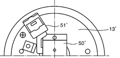
即ち、円筒状の器具本体10’と、器具本体10’内の中心部に配設された反射板20と、反射板20の奥側中心位置に配設されたランプ30’とを有した基本構成となっている。同器具において最も特徴的であるのは、反射板20の前方周縁部分(環状縁部21)に蓄光塗料40が塗布されている点である。以下、第1の実施形態と共通する部分もあるが、各部を詳細に説明する。
That is, a basic unit having a
器具本体10’については、図8に示すように環状のフランジ部11’と、円板状の支持板13’と、支持板13’とフランジ部11’との間を連結する長方形の連結片12’と、連結片12’の外面にネジ止めされた板バネである一対の取付バネ14’とを有した基本構造のものを用いている。支持板12’の外面にはソケット50’がネジ止めされている一方、内面には板バネであるランプ取付バネ15’等がネジ止めされている。支持板12’の面上には、図示されていないが、ソケット50' のランプ接続金具を露出させるための開口が形成されている。
As for the instrument
反射板20については、ランプ30から出た光を前方向に向けて反射させるカップ部22と、カップ部22の前方に位置する環状縁部21と、カップ部22の後方に位置する円筒部23とを有した基本構造のものを用いている。カップ部22の内面にはランプ30’から出た光を乱反射させるために多数のディンプルが形成されている。カップ部22の奥側中心位置にはランプ30’を挿入するための穴(図示せず)が形成されており、円筒部23に連通している。環状縁部21はカップ部22とは異なり平らな湾曲面となっており、この部分に蓄光塗料40が塗布されている。
As for the
このような反射板20がランプ取付バネ15’を用いて器具本体10’に取り付けられる。この状態で反射板20の環状縁部21の端部が器具本体10’のフランジ部11’に位置合わせされる。ここでは反射板20として、カップ部22と環状縁部21とが一体成型されているタイプのものを用いたが、カップ部と環状縁部とが分離されているタイプのものを用いてもかまわない。
Such a
ランプ30’については、ここではHIDランプを用いており、上記したソケット50’のランプ接続金具に着脱可能になっている。ソケット50’に取り付けられた状態のランプ30’は、反射板20の奥側中心であり且つ環状縁部21の奥側に位置するようになっている。なお、ソケット50’に関しては連結端子を兼ねていないことから、支持板13’の上面に連結端子51’が別途取り付けられている。
Here, an HID lamp is used as the lamp 30 ', and the lamp 30' can be attached to and detached from the lamp fitting of the socket 50 '. The
このように構成された照明器具は、図5に示すように天井Aに形成された埋込穴αに挿入されると、取付バネ14’の先端部分が天井Aの裏側に当接し、これで天井Aに取り付けられるようになっている。そして、反射板20の環状縁部21に蓄光塗料40が塗布された構成となっていることから、第1の実施の形態と全く同様の効果を奏する。
When the lighting fixture configured in this way is inserted into the embedding hole α formed in the ceiling A as shown in FIG. 5, the tip of the
なお、本発明に係る照明器具は天井埋込型だけの適用に止まらないのは勿論、スポットライト型等にも同様に適用可能であり、ランプとは異なる別部品のランプ前方に位置する部分に蓄光塗料が塗布された構成である限り、反射板及び器具本体の形状、構造、ランプの種類等に関して特に限定されることはない。 Note that the lighting fixture according to the present invention is not limited to the ceiling-embedded type, but can be similarly applied to a spotlight type or the like. As long as the phosphorescent paint is applied, there is no particular limitation regarding the shape and structure of the reflector and the instrument body, the type of lamp, and the like.
10 器具本体
20 反射板
30 ランプ
40 蓄光塗料
10
Claims (2)
Priority Applications (1)
| Application Number | Priority Date | Filing Date | Title |
|---|---|---|---|
| JP2004107793A JP2005294050A (en) | 2004-03-31 | 2004-03-31 | lighting equipment |
Applications Claiming Priority (1)
| Application Number | Priority Date | Filing Date | Title |
|---|---|---|---|
| JP2004107793A JP2005294050A (en) | 2004-03-31 | 2004-03-31 | lighting equipment |
Publications (1)
| Publication Number | Publication Date |
|---|---|
| JP2005294050A true JP2005294050A (en) | 2005-10-20 |
Family
ID=35326749
Family Applications (1)
| Application Number | Title | Priority Date | Filing Date |
|---|---|---|---|
| JP2004107793A Pending JP2005294050A (en) | 2004-03-31 | 2004-03-31 | lighting equipment |
Country Status (1)
| Country | Link |
|---|---|
| JP (1) | JP2005294050A (en) |
-
2004
- 2004-03-31 JP JP2004107793A patent/JP2005294050A/en active Pending
Similar Documents
| Publication | Publication Date | Title |
|---|---|---|
| JP4755276B2 (en) | Light source for illumination | |
| US20100002451A1 (en) | Tinted and frosted outer bulb cover for lights | |
| JP5549926B2 (en) | Lamp with lamp and lighting equipment | |
| JP2011113940A (en) | Lighting fixture | |
| WO2004016983A1 (en) | Led reflector | |
| JP4655952B2 (en) | lighting equipment | |
| JP2011044412A (en) | Lighting fixture | |
| JP2011076979A (en) | Mounting auxiliary member, and lighting system | |
| JP2014120400A (en) | Led lighting device | |
| JP4092109B2 (en) | lighting equipment | |
| JP2005251637A (en) | Lighting device | |
| JP2010073627A (en) | Illumination device and luminaire | |
| JP3137575U (en) | LED lamp | |
| JP2003123505A (en) | lighting equipment | |
| JP4500700B2 (en) | lighting equipment | |
| JP2005294050A (en) | lighting equipment | |
| JP5419800B2 (en) | lighting equipment | |
| JP2012028124A (en) | Lighting fixture | |
| JP2009283198A (en) | Embedded lighting device | |
| JP5637417B2 (en) | Lamp with lamp and lighting equipment | |
| KR200470160Y1 (en) | The Luminaire | |
| CN214332455U (en) | Lamp combination structure | |
| KR200358913Y1 (en) | Detachable high illuminating reflector | |
| KR20240110255A (en) | Illuminating lamp | |
| KR200269104Y1 (en) | Lampshade for decorative illuminator |
Legal Events
| Date | Code | Title | Description |
|---|---|---|---|
| A131 | Notification of reasons for refusal |
Free format text: JAPANESE INTERMEDIATE CODE: A131 Effective date: 20070327 |
|
| A02 | Decision of refusal |
Free format text: JAPANESE INTERMEDIATE CODE: A02 Effective date: 20070724 |