JP2005294037A - lighting equipment - Google Patents
lighting equipment Download PDFInfo
- Publication number
- JP2005294037A JP2005294037A JP2004107306A JP2004107306A JP2005294037A JP 2005294037 A JP2005294037 A JP 2005294037A JP 2004107306 A JP2004107306 A JP 2004107306A JP 2004107306 A JP2004107306 A JP 2004107306A JP 2005294037 A JP2005294037 A JP 2005294037A
- Authority
- JP
- Japan
- Prior art keywords
- housing
- floor
- support
- main body
- socket
- Prior art date
- Legal status (The legal status is an assumption and is not a legal conclusion. Google has not performed a legal analysis and makes no representation as to the accuracy of the status listed.)
- Withdrawn
Links
Images
Landscapes
- Arrangement Of Elements, Cooling, Sealing, Or The Like Of Lighting Devices (AREA)
- Non-Portable Lighting Devices Or Systems Thereof (AREA)
Abstract
【課題】 埋込ボックスを不要として施工コストを低減することができる照明器具を提供する。
【解決手段】 放電灯Laが収納される収納凹部11aを有し埋込穴F1に収納される本体部11及び収納凹部11aの開口の周囲に突出した鍔部12を有するハウジング1と、鍔部12との間で床材Fを挟持する取付金具8とを備える。また、ハウジング1には、床材Fに螺合する木ねじSCが挿通されるねじ挿通穴11bを設けた。取付金具8や木ねじSCを用いてハウジング1を床材Fに固定することができ、したがって埋込ボックスが不要であるから、施工コストを低減することができる。
【選択図】図1PROBLEM TO BE SOLVED: To provide a lighting fixture capable of reducing the construction cost by eliminating an embedded box.
SOLUTION: A housing 1 having a housing recess 11a in which a discharge lamp La is housed and having a main body 11 housed in an embedding hole F1 and a flange 12 protruding around the opening of the housing recess 11a, and a flange And a mounting bracket 8 that sandwiches the flooring material F with the flooring F. Further, the housing 1 is provided with a screw insertion hole 11b through which a wood screw SC that is screwed into the floor material F is inserted. The housing 1 can be fixed to the floor material F by using the mounting bracket 8 and the wood screw SC, and therefore an embedded box is unnecessary, so that the construction cost can be reduced.
[Selection] Figure 1
Description
本発明は、床下に埋込配設される床埋込型の照明器具に関するものである。 The present invention relates to a floor-mounted lighting fixture that is embedded under a floor.
従来から、床下に埋込配設される床埋込型の照明器具が提供されている。 2. Description of the Related Art Conventionally, a floor-embedded lighting fixture that is embedded under a floor has been provided.
この種の照明器具は、天井に配設される一般的な照明器具では照明されにくい室内の低い位置を重点的に照明することにより独特の雰囲気を演出することができ、しかも電気スタンドと違って室内の空間を占有することのないものである。 This kind of luminaire can produce a unique atmosphere by focusing on the low position in the room which is difficult to illuminate with the general luminaires installed on the ceiling, and unlike the desk lamp It does not occupy indoor space.
従来、この種の照明器具を床下に配設する際は、床下に埋め込まれるとともに照明器具が取り付けられる専用の埋込ボックスを用いて配設されていた(例えば、特許文献1参照)。
しかし、上記従来の床埋込型の照明器具は、配設の際に、照明器具のハウジングの形状に応じた専用の埋込ボックスが必要であったため、施工コストがかさむという欠点があった。 However, the above-mentioned conventional floor-embedded lighting fixture has a drawback in that the installation cost is increased because a dedicated embedding box corresponding to the shape of the housing of the lighting fixture is required for installation.
本発明は上記事由に鑑みて為されたものであり、その目的は、埋込ボックスを不要として施工コストを低減することができる床埋込型の照明器具を提供することにある。 This invention is made | formed in view of the said reason, The objective is to provide the floor-embedded type lighting fixture which can reduce a construction cost by making an embedded box unnecessary.
請求項1の発明は、床面に設けられた埋込穴に埋込配設される照明器具であって、光源が取り付けられるソケットと、ソケットを通じて光源に電源を供給する電源供給手段と、光源及びソケットが収納される収納凹部を有し埋込穴に収納される本体部並びに本体部の収納凹部の開口面に沿って本体部の外側へ突出し床面に載置される鍔部を有するハウジングと、透光性を有する材料からなりハウジングの収納凹部を閉塞する蓋体と、鍔部との間で床材を挟むことによりハウジングを床材に取り付ける取付部材とを備えることを特徴とする。
The invention according to
この発明によれば、取付部材を用いた取り付けが可能となり専用の埋込ボックスが不要となるから、施工コストを低減することができる。 According to the present invention, attachment using the attachment member is possible, and a dedicated embedded box is not necessary, so that the construction cost can be reduced.
請求項2の発明は、床面に設けられた埋込穴に埋込配設される照明器具であって、光源を点灯させる点灯手段と、光源が収納される収納凹部を有し埋込穴に収納される本体部並びに本体部の収納凹部の開口面に沿って本体部の外側へ突出し床面に載置される鍔部を有するハウジングと、透光性を有する材料からなりハウジングの収納凹部を閉塞する蓋体とを備え、ハウジングの本体部において埋込穴の内周面に対向する部位に、床材に螺合するねじが挿通されるねじ挿通穴を収納凹部の内外に貫設したことを特徴とする。
The invention of
この発明によれば、ハウジングを床材へねじ止めすることができて専用の埋込ボックスが不要となるから、施工コストを低減することができる。 According to the present invention, the housing can be screwed to the flooring material, and a dedicated embedding box is not required, so that the construction cost can be reduced.
請求項3の発明は、請求項1又は請求項2の発明において、金属からなり床面に載置されて蓋体を支持する支持体を備えることを特徴とする。 According to a third aspect of the present invention, in the first or second aspect of the present invention, there is provided a support body that is made of metal and is placed on the floor surface and supports the lid body.
この発明によれば、踏まれた場合などで蓋体が下向きの強い力を受けても、蓋体が受けた力を金属からなる支持体が受けて床面に逃がすことになるから、ハウジングの破損を防ぐことができる。 According to the present invention, even if the lid receives a strong downward force when stepped on, the metal support receives the force received by the lid and releases it to the floor surface. Damage can be prevented.
請求項4の発明は、請求項3の発明において、支持体は床面に直交する方向から見て蓋体を全周に亙って囲む枠状に形成され、蓋体と支持体との間の隙間並びに支持体と床面との間の隙間をパッキンで閉塞したことを特徴とする。 According to a fourth aspect of the present invention, in the third aspect of the present invention, the support is formed in a frame shape surrounding the cover over the entire circumference when viewed from the direction orthogonal to the floor surface, and between the cover and the support. And the gap between the support and the floor are closed with packing.
この発明によれば、収納凹部内への水の浸入や空調の効率の低下を防ぐことができる。 According to this invention, it is possible to prevent water from entering the storage recess and a decrease in the efficiency of air conditioning.
請求項5の発明は、請求項3の発明において、支持体は床面に直交する方向から見て蓋体を全周に亙って囲む枠状に形成され、支持体の上面の外周部に、蓋体から離れるほど床面との間の距離を小さくする傾斜面を設けたことを特徴とする。 According to a fifth aspect of the present invention, in the third aspect of the present invention, the support is formed in a frame shape surrounding the cover over the entire circumference when viewed from the direction orthogonal to the floor surface, and is formed on the outer peripheral portion of the upper surface of the support. In addition, an inclined surface is provided which decreases the distance from the floor surface as the distance from the lid body increases.
この発明によれば、掃除機などのキャスターが支持体を乗り越えやすくなる。 According to this invention, a caster such as a vacuum cleaner can easily get over the support.
請求項6の発明は、請求項3の発明において、支持体にヘアライン加工を施したことを特徴とする。
The invention of
この発明によれば、見栄えが向上する上に、支持体に傷がついた場合にも傷が目立ちにくくなる。 According to the present invention, the appearance is improved, and even when the support is damaged, the damage is less noticeable.
請求項7の発明は、請求項1乃至6のいずれかの発明において、電源供給手段からソケットへの給電路に挿入され収納凹部内の温度が異常に高くなったことを検知してソケットへの電源の供給を停止させる電源停止手段を備えることを特徴とする。
The invention according to
この発明によれば、収納凹部内の過熱が防止されるから、安全性の向上が可能となる。 According to this invention, since overheating in the storage recess is prevented, safety can be improved.
ハウジングの鍔部との間で床材を挟むことによりハウジングを床材に取り付ける取付部材を備え、又は、ハウジングの本体部において埋込穴の内周面に対向する部位に、床材に螺合するねじが挿通されるねじ挿通穴を収納凹部の内外に貫設したので、取付部材やねじを用いて床材にハウジングを直接取り付けることができて専用の埋込ボックスが不要となるから、施工コストが低減される。 A mounting member that attaches the housing to the floor material by sandwiching the floor material with the flange of the housing is provided, or is screwed to the floor material at a position facing the inner peripheral surface of the embedding hole in the main body of the housing. Since the screw insertion hole through which the screw to be inserted penetrates inside and outside of the storage recess, the housing can be directly attached to the floor using mounting members and screws, and a dedicated embedding box is not required. Cost is reduced.
以下、本発明を実施するための最良の形態について、図面を参照しながら説明する。 The best mode for carrying out the present invention will be described below with reference to the drawings.
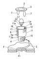
本実施形態は、図2に示すように床材Fに貫設された埋込穴F1に埋込配設されるものであって、光源としての電球型の放電灯Laが取り付けられるソケット4と、放電灯La及びソケット4が収納される収納凹部11aが設けられ埋込穴F1に収納される本体部11並びに収納凹部11aの開口面に沿って収納凹部11aの外側へ突設され床材Fの上面(以下、「床面」と呼ぶ。)に載置される鍔部12を有するハウジング1と、収納凹部11aを閉塞する蓋体2と、蓋体2を支持する支持体3とを備える。
As shown in FIG. 2, the present embodiment is embedded in an embedded hole F1 penetrating through the floor material F, and includes a
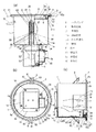
図1を用いて詳しく説明すると、ハウジング1は、上面が開放された有底円筒形状に形成され上端面の外周に鍔部12が突設されたハウジング本体1aと、上面が開放された有底角筒形状に形成されてソケット4が収納されハウジング本体1aの下側に取り付けられるソケット収納体1bとからなる。
Describing in detail with reference to FIG. 1, the
放電灯Laは、例えばバルブL1と、電子安定器が収納された本体部L2と、ソケット4に螺合する口金L3とからなる。
The discharge lamp La includes, for example, a bulb L1, a main body L2 in which an electronic ballast is accommodated, and a base L3 that is screwed into the
ハウジング本体1aの底面には、放電灯LaのバルブL1が挿通される挿通穴13が設けられている。また、ソケット収納体1bの上端部には、開口面の4辺からそれぞれ突出する取付片14が設けられている。ソケット収納体1bは、取付片14を貫通して収納凹部11aの底面に螺合するねじによってハウジング本体1aにねじ止めされている。
An
ソケット収納体1bの側面には、電源供給手段として、商用電源から点灯回路に電源を供給する電源コードC(図2参照)を接続するための例えば速結端子構造を有する端子台15が設けられている。また、ソケット収納体1bには、端子台15からソケット4への給電路に挿入され収納凹部11a内の温度が異常に上昇したときに端子台15から点灯回路への電源の供給を停止させる電源停止手段としてのサーマルプロテクタ5が収納されている。サーマルプロテクタ5は、例えば、固定接点(図示せず)と、バイメタル(図示せず)によって支持され常温では固定接点に接触導通した可動接点(図示せず)とを有し、収納凹部11a内の温度が異常に上昇したときにバイメタルが変形して可動接点が固定接点から離れることにより端子台15から点灯回路への電源の供給を停止させるものである。サーマルプロテクタ5を設けたことにより、例えばソケット4に誤って発熱量の多い白熱灯が取り付けられた場合や、蓋体2の上にマットなどが敷かれて放熱性が低下した場合であっても、収納凹部11a内の過熱が防止されて安全性が向上している。
On the side surface of the
蓋体2は、強化処理が施された透明なガラスからなり円盤形状に形成されたガラスパネル2aと、透光性を有する乳白色のアクリル樹脂からなり円盤形状に形成されガラスパネル2aの下側に重ねて配置されるアクリルパネル2bとからなる。
The
支持体3は、アルミダイキャストからなり全体として円環形状に形成され、蓋体2が収納される貫通穴31aが上下に貫設された枠本体31と、枠本体31の上端部に貫通穴31aの開口面に沿って外側へ全周に亙って突設され床面に載置されるフランジ部32とを有する。
The
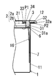
貫通穴31aの内周面には、上側の開口を下側の開口よりも小さくする段33が設けられている。また、ガラスパネル2aには、上端の外径を下端の外径よりも小さくする段21が設けられ、ガラスパネル2aの外周の段21は支持体3の内周の段33に当接している。そして、ガラスパネル2aの下側に配置されたアクリルパネル2bの下面の周縁部に当接して支持体3にねじ止めされる環状の保持枠6によって、ガラスパネル2aとアクリルパネル2bとは支持体3に取り付けられている。さらに、支持体3の段33の下面には環状の溝34が設けられ、溝34にはパッキンP1が保持されている。このパッキンP1によって、蓋体2と支持体3との間の隙間が閉塞され、収納凹部11a内への水の浸入や空調の効率の低下が防止されている。
A
ここで、蓋体2の上面と支持体3の上面とは略面一に形成されている。これにより、蓋体2の上面と支持体3の上面との間に段差が生じる場合に比べて見栄えが向上する上に、前記段差でのつまずきが防止されている。
Here, the upper surface of the
また、支持体3の下面の両端部には、図1(c)及び図3に示すようにそれぞれ例えば金属のようなばね性を有する材料からなりU字形状に形成された取付ばね7の上端部が取り付けられている。取付ばね7は上下方向の中間部同士を離すように曲げられている。そして、ハウジング本体1aにおいてそれぞれ取付ばね7に近接する部位であって取付ばね7の上下方向の中間部よりも上側に位置する各部位には、それぞれ収納凹部11aの内側へ突出しハウジング本体1aの内周面に沿って取付ばね7を挟む各2個の挟み片16が例えば切り起こしによって設けられている。ここで、挟み片16の間隔は取付ばね7の上下方向の中間部の幅寸法よりも小さく且つ上端部の幅寸法よりも大きく形成されている。そして、取付ばね7の位置と挟み片16の位置とを合わせて支持体3の枠本体31を収納凹部11aに挿入すると、各取付ばね7がそれぞれ上下方向の中間部を互いに近付けるように変形しながら挟み片16の間に導入され、取付ばね7の上下方向の中間部が挟み片よりも下側に至ったときに取付ばね7が復帰する。ここにおいて取付ばね7が挟み片16に係止され、支持体3をハウジング1に保持する保持力が生じる。ここで、支持体3の枠本体31の外径はハウジング1の収納凹部11aの内径よりも僅かに小さくしてあり、支持体3の枠本体31がハウジング1の収納凹部11aに挿入されることによって、支持体3はハウジング1に対して位置決めされる。なお、支持体3をハウジング1から取り外すときは、取付ばね7が変形する程度の力で支持体3を引き上げれば、取付ばね7の挟み片16への係止を解除することができる。
Further, at both ends of the lower surface of the
また、ハウジング1の鍔部12には上下両面に跨ってパッキンP2を取り付けてあり、このパッキンP2によって支持体3と床面との間の隙間が閉塞されるようになっている。支持体3と床面との間のパッキンP2によって気密性が向上するので、相当隙間面積の増大が防止され、したがって空調の効率の低下が防止されている。
In addition, a packing P2 is attached to the
さらに、支持体3のフランジ部32の下面には、ハウジング1の鍔部12が収納される凹部32aを設けてある。そして、蓋体2が踏まれた場合など蓋体2又は支持体3が下方へ押力を受けてパッキンP2が潰れた場合には、ハウジング1に応力がかかる前に支持体3のフランジ部32の下面の周縁部が床面に当接するようになっている。この構成により、蓋体2が受けた下向きの力を支持体3が床面に逃がすことになり、ハウジング1が応力を受けることがないから、ハウジング1の破損が防止されている。さらに本実施形態では、強化処理を施されたガラスからなるガラスパネル2aを蓋体2に用い、支持体3をアルミダイキャストで形成したことにより、340Nの静荷重に耐えることが可能となっており、すなわち人が踏んで破損することはほぼ有り得ない強度となっている。なお、強化処理を施されたガラスに代えて、ポリカーボネイトを用いてもよい。
Furthermore, a
また、支持体3の上端の外周の角を落とすことにより、支持体3の上面の周縁部には、蓋体2から離れるほど床面からの突出寸法を小さくする傾斜面35を全周に亙って設けてある。この構成により、掃除機等のキャスターが支持体3を乗り越えやすくなっている。さらに、支持体3と床面との間の段差でのつまづきを防止するためには、床面からの支持体3の突出寸法は7mm以下(例えば5.5mm)とすることが望ましい。
In addition, by lowering the corners of the outer periphery of the upper end of the
また、支持体3の上面にはヘアライン加工が施されている。この構成により、見栄えが向上するとともに、支持体3に傷がついても目立ちにくくなっている。さらに、傷防止のためには、支持体3には耐磨耗性が高い金属(例えばニッケル)のめっきを施すことが望ましい。
Further, the upper surface of the
以下、本発明の要旨である、ハウジング1を床材Fに対して固定する手段について説明する。ハウジング本体1aの外周面には、互いに反対側に位置する2箇所に、上下に長い凹部17が設けられ、各凹部17の底面には、それぞれ上下に長く下端部の幅寸法が他の部位よりも大きく形成された逆T字形状の挿通穴18が貫設されている。挿通穴18には、床材Fをハウジング1の鍔部12との間で挟持する取付部材としての取付金具8が取り付けられる。
Hereinafter, the means for fixing the
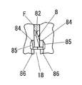
次に、取付金具8の形状について説明する。以下では、ハウジング本体1aの中心軸から離れる方向を前方と呼ぶ。取付金具8は、金属板が曲げ形成されてなり、前後に長い長方形状に形成され床材の下面に当接する床材側当接部81と、床材側当接部81の左右両端からそれぞれ下方に突設されて互いに対向し斜め後方に延長され左右にばね性を有する連結部82と、各連結部82の下端からそれぞれ外側へ突設された側部83と、各連結部82の後端からそれぞれ外側へ突設され前面がハウジング1の内面に当接するハウジング側当接部84と、ハウジング側当接部84の外側の端からそれぞれ後方へ突設され下端が内側へ曲げられてL字形状に形成された操作部85(図4参照)を有する。ここで、各側部83の前端部及び後端部と連結部82との間にはそれぞれスリットを設けてある。そして、各側部83はそれぞれ前端部が上下方向のばね性を有して床材Fの下面に弾接し、後端部が前後方向のばね性を有してハウジング本体1aの外周面に弾接するようになっている。また、ハウジング側当接部84の下端にはハウジング1の内面に対向し前後方向のばね性を有するばね部86が突設されている。
Next, the shape of the mounting
取付金具8をハウジング1に取り付けるには、床材側当接部81と連結部82と側部83とを、挿通穴18の下端を通じてハウジング1の内側から外側へ挿通し、操作部85を互いに近付けるように力を加えながら挿通穴18の縁部をハウジング側当接部84と側部83との間に導入するようにして取付金具8を上方へスライドさせる。すると、各連結片82がそれぞれ挿通穴18の内周面に弾接するとともに、側部83の後端とハウジング側当接部84とが挿通穴18の縁部を挟持することにより、取付金具8がハウジング1に保持される。
In order to attach the mounting
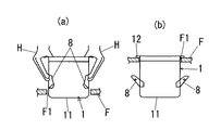
上記の取付金具8を用いて本実施形態を床下に埋込配設するには、ハウジング1の内面に当接するばね部86のばね力に抗して図5(a)に示すように手Hで床材側当接部81と連結部82と側部83とを挿通穴18に押し込みながら、ハウジング1の本体部11を埋込穴F1に収納する。取付金具8が床材Fの下側に至ると、ばね部86のばね力により、図5(b)に示すように取付金具8が復帰し、ハウジング1の埋込穴F1からの抜け止めがなされる。次に、取付金具8を上方へスライドさせて側部83の前端部及び床材側当接部81を床材Fの下面に当接させる。ここにおいて、図1(c)に示すように取付金具8の床材側当接部81とハウジング1の鍔部12との間に床材Fが挟まれ、ハウジング1が床材Fに対して固定される。
In order to embed and dispose the present embodiment under the floor using the mounting
また、ハウジング1には、ねじ挿通穴11bが内外に貫設されていて、本実施形態は、ねじ挿通穴11bに挿通されて図1(a)に示すように床材Fに螺合する木ねじSCによって固定することもできるようになっている。なお、本実施形態では、ねじ挿通穴11bは、挟み片16の切り起こしによって形成された穴とともに、ハウジング本体1aの外面に貼着されたラベルLBで閉塞され、ねじ挿通穴11bを用いる際は木ねじSCにラベルLBを貫通させるようになっている。
Further, the
取付金具8又は木ねじSCを用いてハウジング1を床材Fに固定した後は、放電灯Laをソケット4に取り付け、次に、蓋体2が取り付けられた支持体3をハウジング1に取り付けて施工が完了する。
After the
ここで、支持体3をハウジング1に取り付ける前に、挿通穴18や、木ねじSCを用いた場合における木ねじSCとねじ挿通穴11bの内周面との間の隙間を、例えば粘着テープSEで封印し、収納凹部11aの内外に連通する隙間の幅は最大でも0.5mm以下とすることが、収納凹部11a内への昆虫等の異物の侵入や空調の効率の低下を防ぐためには望ましい。本実施形態では、蓋体2と支持体3との間のパッキンP1、支持体3と床面との間のパッキンP2、ラベルLB並びに粘着テープSEにより、収納凹部1aの内外に連通する隙間の総面積を0.1cm2以下としてある。
Here, before attaching the
上記構成によれば、取付金具8または木ねじSCを用いて床材Fに直接取り付けることができるから、従来例のような埋込ボックスが不要となって施工コストが低減される。
According to the said structure, since it can attach directly to the flooring F using the
また、取付金具8とねじ挿通穴11bとの両方を備えるので、例えば床材Fの厚みが25mm以上であれば木ねじSCを使用し、25mm未満であれば取付金具8を使用するというように床材Fの厚みに応じて取付方法を選ぶことができる。
Further, since both the mounting
なお、施工時に根太との干渉を避けるためには、埋込穴F1の形状を260mm四方の正方形に収まる形状(例えば直径125mmの円形)とすることができるようにハウジング1の寸法を設定することが望ましい。また、一般的な住宅の2階床下にも確実に配設できるように、埋込深さすなわちハウジング1の鍔部12の下端面からハウジング1の下端までの上下の寸法は200mm以下(例えば175mm)とすることが望ましい。
In order to avoid interference with joists during construction, the dimensions of the
ここで、本実施形態では光源として放電灯Laを例に挙げて説明したが、光源は必ずしも放電灯Laでなくともよく、例えば白熱灯を用いることも可能ではある。但し、住宅に配設された場合には蓋体2に人の足などが直に触れる可能性が高いことや、ブローイング等の断熱施工が施された床下に埋込配設された場合には放熱性が著しく低下することを考慮すると、光源としてはやはり発熱量が比較的に少ない放電灯Laを用いることが望ましい。
In this embodiment, the discharge lamp La is described as an example of the light source. However, the light source is not necessarily the discharge lamp La, and for example, an incandescent lamp can be used. However, when it is installed in a house, there is a high possibility that a person's foot etc. will touch the
1 ハウジング
2 蓋体
3 支持体
4 ソケット
5 サーマルプロテクタ
8 取付金具
11 本体部
11a 収納凹部
11b ねじ挿通穴
12 鍔部
F 床材
F1 埋込穴
La 放電灯
SC 木ねじ
DESCRIPTION OF
Claims (7)
光源が取り付けられるソケットと、ソケットを通じて光源に電源を供給する電源供給手段と、光源及びソケットが収納される収納凹部を有し埋込穴に収納される本体部並びに本体部の収納凹部の開口面に沿って本体部の外側へ突出し床面に載置される鍔部を有するハウジングと、透光性を有する材料からなりハウジングの収納凹部を閉塞する蓋体と、鍔部との間で床材を挟むことによりハウジングを床材に取り付ける取付部材とを備えることを特徴とする照明器具。 A lighting fixture that is embedded in an embedding hole provided on the floor surface,
A socket to which a light source is attached; power supply means for supplying power to the light source through the socket; a main body portion having a storage recess for storing the light source and the socket and stored in the embedding hole; and an opening surface of the storage recess in the main body portion Between the housing and the housing having a flange projecting to the outside of the main body portion and placed on the floor, a lid made of a translucent material and closing the housing recess of the housing, and the flange And a mounting member for attaching the housing to the flooring by sandwiching the housing.
光源を点灯させる点灯手段と、光源が収納される収納凹部を有し埋込穴に収納される本体部並びに本体部の収納凹部の開口面に沿って本体部の外側へ突出し床面に載置される鍔部を有するハウジングと、透光性を有する材料からなりハウジングの収納凹部を閉塞する蓋体とを備え、
ハウジングの本体部において埋込穴の内周面に対向する部位に、床材に螺合するねじが挿通されるねじ挿通穴を収納凹部の内外に貫設したことを特徴とする照明器具。 A lighting fixture that is embedded in an embedding hole provided on the floor surface,
A lighting means for turning on the light source, a main body portion that has a storage recess for storing the light source and is stored in the embedding hole, and protrudes to the outside of the main body portion along the opening surface of the storage recess of the main body portion and is placed on the floor A housing having a flange portion, and a lid that is made of a light-transmitting material and closes the housing recess of the housing,
A lighting apparatus, wherein a screw insertion hole through which a screw to be screwed into a floor material is inserted is formed in a portion of the main body of the housing facing the inner peripheral surface of the embedding hole, inside and outside the housing recess.
Priority Applications (1)
| Application Number | Priority Date | Filing Date | Title |
|---|---|---|---|
| JP2004107306A JP2005294037A (en) | 2004-03-31 | 2004-03-31 | lighting equipment |
Applications Claiming Priority (1)
| Application Number | Priority Date | Filing Date | Title |
|---|---|---|---|
| JP2004107306A JP2005294037A (en) | 2004-03-31 | 2004-03-31 | lighting equipment |
Publications (1)
| Publication Number | Publication Date |
|---|---|
| JP2005294037A true JP2005294037A (en) | 2005-10-20 |
Family
ID=35326738
Family Applications (1)
| Application Number | Title | Priority Date | Filing Date |
|---|---|---|---|
| JP2004107306A Withdrawn JP2005294037A (en) | 2004-03-31 | 2004-03-31 | lighting equipment |
Country Status (1)
| Country | Link |
|---|---|
| JP (1) | JP2005294037A (en) |
Cited By (2)
| Publication number | Priority date | Publication date | Assignee | Title |
|---|---|---|---|---|
| JP2016152162A (en) * | 2015-02-18 | 2016-08-22 | アイリスオーヤマ株式会社 | Device body and led lighting device |
| CN114263895A (en) * | 2021-12-21 | 2022-04-01 | 上海双树照明工程股份有限公司 | Lighting lamp structure and construction method thereof |
-
2004
- 2004-03-31 JP JP2004107306A patent/JP2005294037A/en not_active Withdrawn
Cited By (3)
| Publication number | Priority date | Publication date | Assignee | Title |
|---|---|---|---|---|
| JP2016152162A (en) * | 2015-02-18 | 2016-08-22 | アイリスオーヤマ株式会社 | Device body and led lighting device |
| CN114263895A (en) * | 2021-12-21 | 2022-04-01 | 上海双树照明工程股份有限公司 | Lighting lamp structure and construction method thereof |
| CN114263895B (en) * | 2021-12-21 | 2024-04-12 | 上海双树照明工程股份有限公司 | Lighting lamp structure and construction method thereof |
Similar Documents
| Publication | Publication Date | Title |
|---|---|---|
| JP4637251B2 (en) | Lighting equipment | |
| WO2010143577A1 (en) | Illumination device | |
| JP2014026803A (en) | Lighting apparatus | |
| JP5793274B1 (en) | LED lighting device | |
| JP2018097923A (en) | Lighting fixture | |
| KR102042122B1 (en) | Sensor lamp for entrance | |
| US20100002452A1 (en) | Luminaire housing with separated lamp and ballast compartments | |
| JP2010287581A (en) | Lighting system | |
| JP4333432B2 (en) | Downlight | |
| JP2005294037A (en) | lighting equipment | |
| US20160265761A1 (en) | Electrical box having led night lamp and method for manufacturing the same | |
| JP2018097924A (en) | Lighting fixture | |
| KR101635147B1 (en) | LED down light device and it's method for assembling | |
| JP4678377B2 (en) | lighting equipment | |
| JP2008277191A (en) | Wiring equipment | |
| CN219775669U (en) | LED lamp | |
| JP5610612B2 (en) | lighting equipment | |
| JP2008262763A (en) | Recessed ceiling lighting fixture | |
| KR100641816B1 (en) | Wiring duct with reflector | |
| JP4678378B2 (en) | lighting equipment | |
| CN223537465U (en) | A type of downlight with a plastic-faced ring that emits light from the side. | |
| JP7527192B2 (en) | Light source unit and lighting fixture | |
| KR200316316Y1 (en) | fluorescent lamp fixtures | |
| JP3729489B2 (en) | lighting equipment | |
| JP2025149725A (en) | lighting fixtures |
Legal Events
| Date | Code | Title | Description |
|---|---|---|---|
| A300 | Withdrawal of application because of no request for examination |
Free format text: JAPANESE INTERMEDIATE CODE: A300 Effective date: 20070605 |