JP2005294032A - Lighting control system - Google Patents
Lighting control system Download PDFInfo
- Publication number
- JP2005294032A JP2005294032A JP2004107295A JP2004107295A JP2005294032A JP 2005294032 A JP2005294032 A JP 2005294032A JP 2004107295 A JP2004107295 A JP 2004107295A JP 2004107295 A JP2004107295 A JP 2004107295A JP 2005294032 A JP2005294032 A JP 2005294032A
- Authority
- JP
- Japan
- Prior art keywords
- control
- signal
- unit
- control signal
- operation terminal
- Prior art date
- Legal status (The legal status is an assumption and is not a legal conclusion. Google has not performed a legal analysis and makes no representation as to the accuracy of the status listed.)
- Granted
Links
Images


Classifications
-
- Y—GENERAL TAGGING OF NEW TECHNOLOGICAL DEVELOPMENTS; GENERAL TAGGING OF CROSS-SECTIONAL TECHNOLOGIES SPANNING OVER SEVERAL SECTIONS OF THE IPC; TECHNICAL SUBJECTS COVERED BY FORMER USPC CROSS-REFERENCE ART COLLECTIONS [XRACs] AND DIGESTS
- Y02—TECHNOLOGIES OR APPLICATIONS FOR MITIGATION OR ADAPTATION AGAINST CLIMATE CHANGE
- Y02B—CLIMATE CHANGE MITIGATION TECHNOLOGIES RELATED TO BUILDINGS, e.g. HOUSING, HOUSE APPLIANCES OR RELATED END-USER APPLICATIONS
- Y02B20/00—Energy efficient lighting technologies, e.g. halogen lamps or gas discharge lamps
- Y02B20/40—Control techniques providing energy savings, e.g. smart controller or presence detection
Abstract
Description
本発明は、それぞれ照明負荷を制御する複数の制御端末と、それぞれ照明負荷の制御のために操作される複数の操作端末とを、共通の伝送線路に接続した照明制御システムに関するものである。 The present invention relates to a lighting control system in which a plurality of control terminals that respectively control a lighting load and a plurality of operation terminals that are respectively operated for controlling the lighting load are connected to a common transmission line.
従来から、それぞれ照明負荷を制御する複数の制御端末と、それぞれ照明負荷の制御のために操作される複数の操作端末とを、共通の伝送線路に接続した照明制御システムにおいて、信号の衝突を防ぐために種々の方法が提案されている(例えば、特許文献1参照)。 Conventionally, in a lighting control system in which a plurality of control terminals each controlling a lighting load and a plurality of operation terminals each operated to control the lighting load are connected to a common transmission line, signal collision is prevented. Various methods have been proposed for this purpose (see, for example, Patent Document 1).
この種の方法として、例えば、信号の送信権を付与する制御パケット(Token)を伝送線路上に循環させるトークンリング(Token Ring)方式や、制御端末が各操作端末との間で順に通信を行うポーリング(Polling)方式が知られている。 As this type of method, for example, a token ring method that circulates a control packet (Token) that grants a signal transmission right on a transmission line, or a control terminal communicates with each operation terminal in order. A polling method is known.
しかし、制御端末や操作端末の数が多い場合、トークンリング方式では操作されていない操作端末にトークンが滞在する時間が長くなり、ポーリング方式では操作されていない操作端末と制御端末との間の通信で伝送線路が使用される時間が長くなるため、いずれの方式でも操作端末への操作に対する応答が遅くなってしまう。 However, when there are a large number of control terminals and operation terminals, it takes longer for the token to stay at the operation terminal that is not operated by the token ring method, and communication between the operation terminal that is not operated by the polling method and the control terminal. Since the time for which the transmission line is used becomes long, the response to the operation to the operation terminal is delayed by any method.
他には、伝送線路上に信号が存在するか否かを検出する手段を制御端末や操作端末に設け、制御端末や操作端末が信号を送信しようとしたときに伝送線路上に信号が存在するときには信号の送信を延期し、伝送線路上に信号が存在しないときにのみ信号を送信するようにして衝突を低減するCSMA/CD(Carrier Sense Multiple Access with Collision Detection)方式、並びにCSMA/ACK(Carrier Sense Multiple Access with ACKnowledgement)が知られている。CSMA/CD方式やCSMA/ACK方式の場合、制御端末や操作端末の数が多くても、操作端末への操作に対する応答速度の低下は避けられる。
ここで、照明制御システムには、段階的な照度変更が可能であって多段階で照度を変更するときには照度を変更する段階の回数だけ制御信号の送信が必要となるものがある。 Here, some illumination control systems can change the illuminance in stages, and when changing the illuminance in multiple stages, it is necessary to transmit a control signal as many times as the stage of changing the illuminance.
このような照明制御システムにおいて、CSMA/CD方式やCSMA/ACK方式を用いると、例えばある操作端末が複数の制御信号を送信している間に他の操作端末が操作されても、他の操作端末は制御信号を送信中の操作端末が送信を完了するまで待機しなければならないから、ある照明負荷の照度が一気に変化した後に時間をおいて他の照明負荷の照度が変化するといったように、照明負荷の照度変化のタイミングにばらつきが生じることになり、使用者に違和感を与えてしまう。 In such an illumination control system, when the CSMA / CD method or the CSMA / ACK method is used, for example, even if another operation terminal is operated while a certain operation terminal transmits a plurality of control signals, Since the terminal has to wait until the operation terminal that is transmitting the control signal completes transmission, the illuminance of another lighting load changes after a while after the illuminance of one lighting load changes at a stroke, Variations in the timing of the illuminance change of the illumination load will cause a sense of discomfort to the user.
本発明は上記事由に鑑みて為されたものであり、その目的は、制御端末や操作端末の数が多いときの操作端末への操作に対する応答速度の低下を防止しつつ、複数の操作端末が同時に操作された場合にも照明負荷の照度変化のタイミングのばらつきを抑えることができる照明制御システムを提供することにある。 The present invention has been made in view of the above reasons, and its purpose is to prevent a decrease in response speed to an operation to the operation terminal when the number of control terminals and operation terminals is large, An object of the present invention is to provide an illumination control system capable of suppressing variations in timing of illuminance changes of illumination loads even when operated simultaneously.
請求項1の発明は、それぞれ照明負荷を制御する複数の制御端末とそれぞれ制御端末に対応し照明負荷の調光制御のために操作される複数の操作端末とを共通の伝送線路に接続した照明制御システムであって、各操作端末はそれぞれ、照明負荷を調光制御するために操作される操作部と、操作部に加えられた操作に応じた制御信号を生成する制御部と、制御部が生成した制御信号を伝送線路に送信する制御送信部と、信号線を介して他の操作端末に接続され制御部の制御に応じた信号を他の操作端末に送信する操作端末間送信部と、信号線を介して他の操作端末に接続され他の操作端末からの信号を受信して制御部に入力する操作端末間受信部とを有し、各制御端末はそれぞれ、伝送線路を通じて送信された制御信号を受信する受信部と、対応する操作端末からの制御信号が受信部に受信されると該制御信号に応じて照明負荷を調光制御する負荷制御部とを有し、各操作端末の制御部は、制御信号を送信する前に操作端末間送信部を制御して制御信号の内容を示す予告信号を他の操作端末に送信させ、予告信号の送信中に他の操作端末からの予告信号が操作端末間受信部に受信された場合には、うち1台の操作端末においては、制御部は、予告信号を出力した他の全ての操作端末の制御信号と自身の制御信号との内容を含む合成制御信号を生成するとともに、少なくとも予告信号を出力した他の全ての操作端末と自身とにそれぞれ対応する各制御端末を全て含む複数の制御端末を対象として合成制御信号を制御送信部に送信させ、上記1台を除く他の操作端末においては、制御部は制御信号の送信を中止し、制御端末の負荷制御部は、受信部に受信された合成制御信号から自らを対象とする制御信号の内容を検出し、該制御信号の内容に基いて照明負荷を調光制御することを特徴とする。 The invention of claim 1 is an illumination in which a plurality of control terminals each controlling a lighting load and a plurality of operation terminals corresponding to the control terminals and operated for dimming control of the lighting load are connected to a common transmission line. Each of the operation terminals includes an operation unit that is operated to perform dimming control of the lighting load, a control unit that generates a control signal according to an operation applied to the operation unit, and a control unit. A control transmission unit that transmits the generated control signal to the transmission line, an inter-operation terminal transmission unit that is connected to another operation terminal via the signal line and transmits a signal according to the control of the control unit to the other operation terminal, An inter-operation terminal receiving unit that is connected to another operation terminal via a signal line and receives a signal from the other operation terminal and inputs the signal to the control unit, and each control terminal is transmitted through a transmission line A receiver that receives the control signal; When the control signal from the operating terminal is received by the receiving unit, the control unit of each operating terminal has a load control unit that performs dimming control of the lighting load according to the control signal. To control the inter-operation terminal transmission unit to transmit a notice signal indicating the contents of the control signal to other operation terminals, and during the transmission of the notice signal, the advance signal from the other operation terminal is received by the inter-operation terminal reception unit. In such a case, in one of the operation terminals, the control unit generates a combined control signal including the contents of the control signals of all the other operation terminals that output the warning signal and its own control signal, A control signal is transmitted to the control transmitter for a plurality of control terminals including all the control terminals corresponding to each of the other operation terminals that output at least the notice signal and itself, and other than the above one In the operation terminal, the control unit The load control unit of the control terminal detects the content of the control signal intended for itself from the combined control signal received by the receiving unit, and determines the lighting load based on the content of the control signal. It is characterized by dimming control.
この発明によれば、操作されない操作端末及びこれに対応する制御端末は信号の送受信を行わないことにより、操作端末及び制御端末の数が多いときの操作端末への操作に対する応答速度の低下を防止しつつ、操作された各操作端末にそれぞれ対応する各制御端末が合成制御信号を同時に受信することによって略同時に照明負荷を調光制御することになるから、照明負荷の照度変化のタイミングのばらつきが抑えられ、使用者に違和感を与えることがない。さらに、同時に操作された複数の操作端末の制御信号を、操作された操作端末に対応する全ての制御端末を対象とする合成制御信号として1台の操作端末が送信するから、制御信号同士の衝突が防止される。 According to the present invention, an operation terminal that is not operated and a control terminal corresponding to the operation terminal do not transmit / receive signals, thereby preventing a decrease in response speed to an operation to the operation terminal when the number of operation terminals and control terminals is large. However, since each control terminal corresponding to each operated operation terminal simultaneously controls the lighting load by simultaneously receiving the combined control signal, the variation in timing of the illuminance change of the lighting load varies. It is suppressed and does not give the user a sense of incongruity. Further, since the control signals of a plurality of operation terminals operated at the same time are transmitted as a combined control signal for all the control terminals corresponding to the operated operation terminals, one control terminal collides with each other. Is prevented.
請求項2の発明は、請求項1の発明において、各操作端末はそれぞれ、伝送線路上に合成制御信号が存在するか否かを検出する合成制御信号検出手段を有し、各操作端末の制御部は、制御信号の送信を中止してから所定時間以内に合成制御信号が合成制御信号検出手段に検出されなかった場合には操作端末間送信部に再送要求信号を送信させ、合成制御信号を制御送信部に送信させた後に、該合成制御信号に対応する再送要求信号が操作端末間受信部に受信されると、該合成制御信号を再び制御送信部に送信させることを特徴とする。 According to a second aspect of the present invention, in the first aspect of the invention, each operation terminal has a combined control signal detecting means for detecting whether or not a combined control signal exists on the transmission line. When the composite control signal is not detected by the composite control signal detection means within a predetermined time after the transmission of the control signal is stopped, the transmission unit transmits a retransmission request signal to the inter-operation terminal transmission unit, When the retransmission request signal corresponding to the synthesis control signal is received by the inter-operation terminal reception unit after being transmitted to the control transmission unit, the synthesis control signal is transmitted again to the control transmission unit.
この発明によれば、合成制御信号検出手段により合成制御信号の送信の失敗を検出することができ、合成制御信号の送信に失敗した場合には、合成制御信号の送信をやり直すことができる。 According to the present invention, it is possible to detect a failure in transmission of the synthesis control signal by the synthesis control signal detection means, and when transmission of the synthesis control signal fails, transmission of the synthesis control signal can be performed again.
請求項3の発明は、それぞれ照明負荷を制御する複数の制御端末とそれぞれ制御端末に対応し照明負荷の調光制御のために操作される複数の操作端末とを共通の伝送線路に接続した照明制御システムであって、各操作端末はそれぞれ、照明負荷を調光制御するために操作される操作部と、操作部に加えられた操作に応じた制御信号を生成する制御部と、制御部が生成した制御信号を伝送線路に送信する制御送信部と、伝送線路上の信号を検出する信号検出手段とを有し、各制御端末はそれぞれ、伝送線路を通じて送信された制御信号を受信する受信部と、対応する操作端末からの制御信号が受信部に受信されると該制御信号に応じて照明負荷を段階的に調光制御する負荷制御部とを有し、各操作端末の制御部は、制御信号の送信を試みる際に、信号検出手段に他の操作端末の制御信号が検出されている場合、又は信号検出手段に他の操作端末の制御信号が信号検出手段に検出されなくなった後に制御信号の検出に充分な時間である待機時間が経過する以前であった場合には、少なくとも信号検出手段に他の操作端末の制御信号が検出されなくなった後さらに待機時間が経過するまでは制御信号の送信を延期するものであって、操作端末の制御部は、操作端末毎に保有するパラメータである優先度を保持し、自身の優先度が高いほど待機時間を短くし、制御信号の送信を延期している操作端末が存在するときに連続して制御信号を送信することがないように、優先度を随時変更することを特徴とする。 According to a third aspect of the present invention, a plurality of control terminals each controlling a lighting load and a plurality of operation terminals corresponding to the control terminals and operated for dimming control of the lighting load are connected to a common transmission line. Each of the operation terminals includes an operation unit that is operated to perform dimming control of the lighting load, a control unit that generates a control signal according to an operation applied to the operation unit, and a control unit. A control unit that transmits the generated control signal to the transmission line, and a signal detection unit that detects a signal on the transmission line, and each control terminal receives a control signal transmitted through the transmission line. And a load control unit that performs dimming control on the lighting load in accordance with the control signal when a control signal from the corresponding operation terminal is received by the reception unit, the control unit of each operation terminal includes: When trying to send a control signal When the control signal of the other operation terminal is detected by the signal detection means, or after the control signal of the other operation terminal is no longer detected by the signal detection means by the signal detection means, it is sufficient time for detection of the control signal. If it is before the waiting time has elapsed, at least after the control signal of the other operation terminal is no longer detected by the signal detecting means, the transmission of the control signal is postponed until the waiting time has passed. The control unit of the operation terminal holds the priority that is a parameter held for each operation terminal, and there is an operation terminal that delays the waiting time and postpones the transmission of the control signal as its own priority is higher The priority is changed at any time so that the control signal is not continuously transmitted from time to time.
この発明によれば、操作されない操作端末及びこれに対応する制御端末は信号の送受信を行わないことにより操作端末及び制御端末の数が多いときの操作端末への操作に対する応答速度の低下を防止しつつも、複数の操作端末が同時に操作された場合には、操作された操作端末が優先順位の順に1回ずつ制御信号を送信することになるので、照度変化のタイミングのばらつきが抑えられるから、使用者に違和感を与えることがない。 According to the present invention, an operation terminal that is not operated and a control terminal corresponding to the operation terminal do not transmit / receive signals, thereby preventing a decrease in response speed to an operation to the operation terminal when the number of operation terminals and control terminals is large. However, when a plurality of operation terminals are operated at the same time, the operated operation terminals will transmit a control signal once in the order of priority, so variation in the timing of illuminance change can be suppressed. Does not give the user a sense of incongruity.
請求項4の発明は、請求項3の発明において、制御端末は、対応する操作端末からの制御信号が受信部に受信されたときに伝送線路を通じて操作端末に確認信号を送信する送信部を有し、操作端末の制御部は、制御信号を制御送信部に送信させた後、確認信号の操作端末への到達に充分な時間であって待機時間よりも短い所定のタイムアウト時間内に信号検出手段に確認信号が検出されなかった場合には再度、制御信号の送信を試み、他の操作端末の制御信号が信号検出手段に検出されたことで制御信号の送信を延期したとき、並びに制御信号を制御送信部に送信させてからタイムアウト時間内に確認信号が信号検出手段に検出されなかったときに、自身の優先度を上昇させ、制御信号を制御送信部に送信させた後に該制御信号に対応する確認信号が信号検出手段に検出されたときには自身の優先度を最も低くすることを特徴とする。 According to a fourth aspect of the present invention, in the third aspect of the present invention, the control terminal has a transmission unit that transmits a confirmation signal to the operation terminal through the transmission line when a control signal from the corresponding operation terminal is received by the reception unit. Then, the control unit of the operation terminal transmits the control signal to the control transmission unit, and then the signal detection means within a predetermined time-out time that is sufficient for the confirmation signal to reach the operation terminal and shorter than the standby time. If the confirmation signal is not detected, the control signal transmission is attempted again. When the control signal of another operation terminal is detected by the signal detection means, the transmission of the control signal is postponed. When the confirmation signal is not detected by the signal detection means within the timeout period after being sent to the control transmitter, the priority is increased, and the control signal is sent to the control transmitter, and then the control signal is handled. Sure Signal, characterized in that the lowest priority itself when it is detected in the signal detecting means.
この発明は請求項3の発明の実施態様であり、請求項3の発明と同様の効果が得られる。
This invention is an embodiment of the invention of
請求項5の発明は、請求項3又は請求項4の発明において、各操作端末は、信号線を介して他の操作端末に接続され制御部の制御に応じた信号を他の操作端末に送信する操作端末間送信部と、信号線を介して他の操作端末に接続され他の操作端末からの信号を受信して制御部に入力する操作端末間受信部とを有し、操作端末の制御部は、制御信号を制御送信部に送信させる前には制御信号の内容を示す予告信号を操作端末間送信部に送信させ、予告信号の送信中に他の操作端末の予告信号が操作端末間受信部に受信された場合には、予告信号を送信した各操作端末の優先度が全て異なるように自身の優先度を設定することを特徴とする。 According to a fifth aspect of the present invention, in the third or fourth aspect of the present invention, each operation terminal is connected to another operation terminal via a signal line and transmits a signal according to the control of the control unit to the other operation terminal. An inter-operation terminal transmission unit, and an inter-operation terminal reception unit that is connected to another operation terminal via a signal line and receives a signal from the other operation terminal and inputs the signal to the control unit. Before transmitting the control signal to the control transmission unit, the control unit transmits a notification signal indicating the contents of the control signal to the inter-operation terminal transmission unit. When received by the receiving unit, it is characterized in that its own priority is set so that the priorities of the respective operation terminals that have transmitted the warning signal are all different.
この発明によれば、複数の操作端末で優先度が同じになることに起因する衝突の発生が防止されるから、操作端末への操作に対する応答速度が向上する。 According to this invention, since the occurrence of a collision due to the same priority among a plurality of operation terminals is prevented, the response speed to an operation on the operation terminal is improved.
本発明によれば、操作されない操作端末及びこれに対応する制御端末は信号の送受信を行わないようにして、操作端末及び制御端末の数が多いときの操作端末への操作に対する応答速度の低下を防ぎつつも、複数の操作端末が同時に操作された場合には複数の制御端末への制御信号を合成した合成制御信号を対象となる複数の制御端末が略同時に受信することによって略同時に照明負荷を制御し、又は操作された各操作端末が優先順位の順に1回ずつ制御信号を送信することになるから、照明負荷の照度変化のタイミングのばらつきが抑えられ、使用者に違和感を与えることがない。 According to the present invention, an operation terminal that is not operated and a control terminal corresponding to the operation terminal do not perform signal transmission / reception so that a response speed to an operation on the operation terminal is reduced when the number of operation terminals and control terminals is large. While preventing, when a plurality of operation terminals are operated at the same time, the combined control signal obtained by synthesizing the control signals to the plurality of control terminals is received substantially simultaneously by the plurality of target control terminals receiving substantially the same. Since each control terminal that is controlled or operated transmits a control signal once in the order of priority, variation in the timing of illuminance change of the lighting load is suppressed, and the user does not feel uncomfortable. .
以下、本発明を実施するための最良の形態について、図面を参照しながら説明する。 The best mode for carrying out the present invention will be described below with reference to the drawings.
(実施形態1)
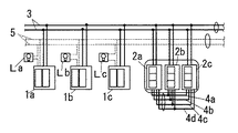
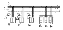
本実施形態は、図1に示すように、それぞれ照明負荷La,Lbを制御する複数(例えば2台)の制御端末1a,1bと、それぞれ制御端末1a,1bに一対一に対応し照明負荷La,Lbの制御のために操作される複数の操作端末2a,2bとを共通の伝送線路3にバス接続したものである。ここで、各制御端末1a,1b並びに各操作端末2a,2bは、それぞれ埋込形の配線器具用の取付枠に取り付け可能な形状のハウジングを有する。そして、各制御端末1a,1bは、それぞれ対応する照明負荷La,Lbに近い位置において例えば壁面に埋込配設され、各操作端末2a,2bは、制御端末1a,1bからは離れた位置において互いに近接して例えば壁面に埋込配設される。
(Embodiment 1)
In the present embodiment, as shown in FIG. 1, a plurality of (for example, two)
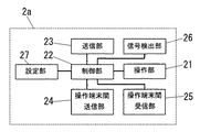
各操作端末2a,2bは、それぞれ図2に示すように、操作端末2a,2bに対応する照明負荷La,Lbを調光制御するために操作される操作部21と、操作部21が操作されたときに操作部21に加えられた操作の内容に応じた制御信号を生成する制御部22と、制御部22が生成した制御信号を伝送線路3を通じて制御端末1a,1bへ送信する送信部23とを有する。操作部21は例えばそれぞれ押操作される押釦ハンドル並びに押釦ハンドルが押操作される毎に出力を生成して制御部22に入力するスイッチを有するアップスイッチとダウンスイッチとからなる。制御部22は例えばマイコンからなり、アップスイッチから信号が入力されたときには照明負荷La,Lbの照度を1段階上げる制御信号を生成し、ダウンスイッチから信号が入力されたときには照明負荷La,Lbの照度を1段階下げる制御信号を生成する。送信部23は例えば制御信号の内容に応じて伝送線路3間にかける電圧をオンオフすることによって制御信号をパルス信号として送信する。また、各操作端末2a,2bはそれぞれいわゆるCSMA方式で制御信号を送信する。すなわち、各操作端末2a,2bは、それぞれ例えば伝送線路3間の電圧を検知することによって伝送線路3上の信号を検出する信号検出部26を有し、制御部22は、送信部23に信号を送信させようとする際に信号検出部26によって伝送線路3上に何らかの信号が検出されていれば、少なくとも信号検出部26に信号が検出されなくなるまでは信号の送信を延期する。ここで、送信部23並びに信号検出部26はそれぞれ従来周知の技術を用いて実現可能であるから、詳細な構成についての図示並びに説明は省略する。なお、図2には1個の操作端末2aのみを示したが、他の操作端末2bも共通の構成を有する。
As shown in FIG. 2, the
ここで、操作端末2a,2b間は信号線4a〜4cを介して接続されていて、各操作端末2a,2bは、制御部22によって駆動され信号線4a〜4cを通じて他の操作端末2a,2bへ信号を送信する操作端末間送信部24と、信号線4a〜4cを通じて他の操作端末2a,2bから送信された信号を制御部22に入力する操作端末間受信部25とを有する。信号線4a〜4cは、例えばそれぞれ1台ずつの操作端末2a,2bに対応した信号線4a,4bと、共通の信号線4cとからなる。各操作端末2a,2bにおいて、操作端末間送信部24は、自身に対応した信号線4a,4bと共通の信号線4cとを介して、それぞれ近接する他の全ての操作端末2a,2bの操作端末間受信部25に接続されている。操作端末間送信部24は例えば信号の内容に応じた電圧を自身の操作端末2a,2bに対応した信号線4a,4bと基準電位の信号線4cとの間に加えることで他の操作端末2a,2bに信号を送信する。操作端末間受信部25は例えば自身の操作端末2a,2bに対応しない信号線4a,4bと基準電位の信号線4cとの間の電圧を検出することで他の操作端末2a,2bからの信号を受信する。なお、操作端末間送信部24並びに操作端末間送信部25はそれぞれ従来周知の技術を用いて実現可能であるから、詳細な構成についての図示並びに説明は省略する。
Here, the
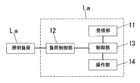
各制御端末1a,1bは、それぞれ図3に示すように、例えば伝送線路3間の電圧を検出することによって制御信号を受信する受信部11と、照明負荷La,Lbを調光制御する負荷制御部12と、制御信号が受信部11に受信されたときに該制御信号に基いて負荷制御部12に照明負荷La,Lbを制御させる制御部13とを備える。ここで、制御端末1a,1bと操作端末2a,2bとはアドレスによって対応付けられており、制御信号には対象となる制御端末1a,1bに対応したアドレスが含まれている。制御部13は例えばマイコンからなり、自身に対応するアドレスを含む制御信号が受信部11に受信されたときに、該制御信号に応じて負荷制御部12を制御する。負荷制御部12は、例えば照明負荷La,Lbに給電するためのAC100Vの電源に接続された給電路5に挿入され、照明負荷La,Lbへ供給する電力量を調整することにより照明負荷La,Lbを調光制御する。受信部11は例えば伝送線路3から受信された制御信号を制御部13に入力される信号に変換する。ここで、受信部11並びに負荷制御部12はそれぞれ従来周知の技術を用いて実現可能であるから、詳細な構成についての図示並びに説明は省略する。また、各制御端末1a,1bは、照明負荷La,Lbを調光制御するために操作される操作端末2a,2bと同様の操作部14を備え、制御部13は、操作部14が操作されたときに、操作部14に加えられた操作に応じて照明負荷La,Lbを調光制御する。すなわち、制御端末1a,1bの操作部14を操作することによっても照明負荷La,Lbを調光制御することができるようになっている。なお、図3には1個の制御端末1aのみを示したが、他の制御端末1bも共通の構成を有する。
As shown in FIG. 3, each
以下、本実施形態の要旨である操作端末2a,2bの動作を説明する。
Hereinafter, the operation of the
各操作端末2a,2bの制御部22は、操作部21の例えばアップスイッチが操作されると、対応する照明負荷La,Lbの照度を上げる制御信号を生成する。そして、生成した制御信号を送信部23に送信させる前に、対応する照明負荷La,Lbの照度を上げることを示す予告信号を操作端末間送信部24に送信させる。
When, for example, an up switch of the
ここで、各操作端末2a,2bはそれぞれ例えばディップスイッチからなる設定部27を有し、設定部27によって操作端末2a,2b間には予め優先順位が設定されている。
Here, each of the
そして、予告時間中に、他の操作端末2a,2bの予告信号が操作端末間受信部25に受信された場合、つまり、複数の操作端末2a,2bで同時にそれぞれ操作部21が操作された場合には、優先順位の最も高い操作端末2aとその他の操作端末2bとで異なる動作が行われる。すなわち、優先順位の最も高い操作端末2aでは、制御部22は、自らの制御信号の内容並びに対象となる制御端末1aの情報と、他の操作端末2bの制御信号の内容並びに対象となる制御端末1bの情報とを全て含む合成制御信号を新たに生成して送信部23に送信させる。ここで、各制御端末1a,1bの制御部13には、全ての制御端末1a,1bを対象とするマルチキャストアドレスが定義されており、自身に対応するアドレスが含まれた制御信号のみならずマルチキャストアドレスが含まれた制御信号も受信するようになっている。そして、合成制御信号にはマルチキャストアドレスが含まれる。つまり、合成制御信号は、複数の制御端末1a,1bを同時に対象とするいわゆるマルチキャストで送信されることになる。また、優先順位が2番目以降の操作端末2bでは、制御信号の送信を中止する。
Then, when the notice signal of the
各制御端末1a,1bでは、合成制御信号が受信部11に受信されると、制御部13は合成制御信号から自身に対する制御信号の内容を検出し、これに基いて例えば照明負荷1a,1bの照度を上げるように負荷制御部12に照明負荷1a,1bを制御させる。
In each
なお、操作部21を操作された操作端末2a,2bにおいて、予告時間中に操作端末間受信部25に他の操作端末2a,2bからの予告信号が受信されなかった場合には、制御部22はそのまま制御信号を送信部23に送信させる。
Note that, in the
上記構成によれば、操作部21を操作されない操作端末2a,2b及びこれに対応する制御端末1a,1bは信号の送受信を行わないことにより、操作端末2a,2b及び制御端末1a,1bの数が多いときの操作端末2a,2bへの操作に対する応答速度の低下を防ぎつつ、同時に操作部21を操作された各操作端末2a,2bにそれぞれ対応する各制御端末1a,1bが略同時に合成制御信号を受信することによって略同時に照明負荷La,Lbを制御することになるので、照明負荷La,Lbの照度変化のタイミングのばらつきが抑えられるから、使用者に違和感を与えることがない。さらに、同時に操作部21を操作された複数の操作端末2a,2bの制御信号を、操作部21を操作された各操作端末2a,2bに対応する全ての制御端末1a,1bを対象とする合成制御信号として1台の操作端末2aが送信するから、制御信号同士の衝突が発生しない。
According to the above configuration, the
なお、本実施形態では制御端末1a,1b及び操作端末2a,2bは2台としたが、図4に示すように操作端末2a〜2cの台数分だけ信号線4a〜4dの本数を増やせば、制御端末1a〜1c及び操作端末2a〜2cを3台以上用いる場合にも対応可能である。
In this embodiment, the
(実施形態2)
本実施形態の基本構成は実施形態1と共通であるので、共通する部分については同じ符号を付して説明を省略する。
(Embodiment 2)
Since the basic configuration of the present embodiment is the same as that of the first embodiment, common portions are denoted by the same reference numerals and description thereof is omitted.
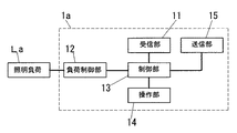
本実施形態は、各操作端末2a,2bが、それぞれCSMA/ACK方式で制御信号を送信するものである。すなわち、各制御端末1a,1bはそれぞれ図5に示すように、制御部13によって制御され信号を伝送線路3を通じて操作端末2a,2bへ送信する送信部15を備える。各制御端末1a,1bの制御部13は、自身を対象とする制御信号が受信部11に受信されたときには、負荷制御部12に照明負荷La,Lbを調光制御させるとともに、所定の確認信号を送信部15に送信させる。なお、送信部15は従来周知の技術を用いて実現可能であるから、詳細な構成についての図示並びに説明は省略する。
In this embodiment, each
各操作端末2a,2bでは、制御部22は、制御信号を送信部23に送信させてから所定のタイムアウト時間以内に確認信号が信号検出部26に検出されなかった場合、同じ制御信号を再度送信する。
In each
ここで、マルチキャストで送信された信号に対して各制御端末1a,1bの制御部13が確認信号を送信部15に送信させると、複数の制御端末1a,1bから送信された確認信号同士が伝送線路3上で衝突してしまうから、CSMA/ACK方式では通常、マルチキャストで送信された信号に対しては確認信号は送信させない。本実施形態でも、合成制御信号はマルチキャストで送信されるものであるから、制御端末1a,1bでは、合成制御信号が受信部11に受信された場合、制御部13は確認信号を送信させない。しかし、このままでは合成制御信号の送信の成否を検出することができない。
Here, when the
そこで、本実施形態では、制御信号の送信を中止した操作端末2bで制御部22が合成制御信号の送信の成否を検出し、合成制御信号の送信の失敗が検出されたときに、合成制御信号を送信した操作端末2aに対し信号線4a〜4cを通じて合成制御信号の再送を要求する。
Therefore, in the present embodiment, when the
具体的には例えば、複数の操作端末2a,2bで同時にそれぞれ操作部21が操作されたときに、優先順位が2番目以降の操作端末2bにおいて、制御信号の送信を中止してから所定時間以内に合成制御信号が信号検出部26に検出されなかった場合、制御部22は、操作端末間送信部24に再送要求信号を送信させる。合成制御信号を送信した操作端末2aでは、操作端末間受信部25に再送要求信号が受信されると、制御部22が再度、合成制御信号を送信部23に送信させる。
Specifically, for example, when the
または、優先順位が2番目以降の操作端末2bにおいて、制御信号の送信を中止した後に合成制御信号が信号検出部26に検出された場合に、制御部22が、操作端末間送信部24に送信確認信号を送信させるようにしてもよい。この場合、合成制御信号を送信した操作端末2aでは、合成制御信号を送信部23に送信させてから所定時間以内に送信確認信号が操作端末間受信部25に受信されなかった場合に、制御部22が再度、合成制御信号を送信部23に送信させる。
Alternatively, in the
上記構成によれば、合成制御信号の送信失敗を検出することができ、合成制御信号の送信失敗が検出されたときには合成制御信号を再度送信させることができる。 According to the above configuration, the transmission failure of the synthesis control signal can be detected, and when the transmission failure of the synthesis control signal is detected, the synthesis control signal can be transmitted again.
(実施形態3)
本実施形態の基本構成は実施形態2と共通であるので、共通する部分については同じ符号を付して説明を省略する。
(Embodiment 3)
Since the basic configuration of the present embodiment is the same as that of the second embodiment, common portions are denoted by the same reference numerals and description thereof is omitted.
本実施形態では、各制御端末1a〜1cの制御部13は、自身を対象とする制御信号が受信部11に受信される度に、照明負荷La〜Lcの照度を段階的に変化させる。また、本実施形態は、図6に示すように、信号線4a〜4dを用いておらず、図7に示すように、各操作端末2a〜2cはそれぞれ操作端末間送信部24及び操作端末間受信部25を有さない。そして、各操作端末2a〜2cがそれぞれ伝送線路3上の信号を監視し、伝送線路3上に制御信号が検出されたとき及び制御信号が検出されなくなってから待機時間は制御信号の送信を延期するようにし、さらに、複数の操作端末2a〜2cで同時にそれぞれ操作部21が操作された場合には、操作部21を操作された操作端末2a〜2cが順に1回ずつ制御信号を送信するように待機時間を調整することにより、照明負荷La〜Lcの照度変化のタイミングのばらつきを抑えるようにしたものである。
In the present embodiment, the
具体的に説明すると、各操作端末2a〜2cの制御部22は、操作部21が操作されると、それぞれ加えられた操作に応じた制御信号を加えられた操作に応じた回数だけ生成する。
More specifically, when the
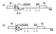
また、各操作端末2a〜2cの制御部22は、それぞれ信号検出部26の出力を監視しており、図8(a)(b)に示すように信号検出部26によって伝送線路3上に制御信号SCが検出されると、少なくとも信号検出部26によって伝送線路3上に制御信号SCが検出されている期間と、伝送線路3上に制御信号SCが検出されなくなった時点TEから所定のタイムアウト時間ΔtOが経過するまでは制御信号の送信を延期する。
Moreover, the
さらに、図8(a)に示すように、タイムアウト時間ΔtOが経過するまでに確認信号SAが信号検出部26に検出された場合、確認信号SAが検出されなくなってからタイムアウト時間ΔtOよりも長い所定のインターフレームギャップ時間ΔtFが経過するまでは送信禁止期間ΔTP1として制御信号の送信を延期する。
Further, as shown in FIG. 8A, when the confirmation signal SA is detected by the
また、図8(b)に示すように、タイムアウト時間ΔtOが経過するまでに確認信号が信号検出部26に検出されなかった場合には、伝送線路3上に制御信号が検出されなくなった時点TEから起算してインターフレームギャップ時間ΔtFが経過した時点までは送信禁止期間ΔTP2として制御信号の送信を延期する。
Further, as shown in FIG. 8B, when the confirmation signal is not detected by the
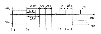
その後さらに所定の単位待機時間Δtuの整数n倍の時間だけ待機し、その時点Tnまでに信号検出部26によって伝送線路3上に次の制御信号SCが検出されていれば、制御信号SCの送信をさらに延期し、伝送線路3上に制御信号SCが検出されていなければ、制御信号SCを送信する。つまり、確認信号SAが検出された場合は、制御信号SCが検出されなくなってから確認信号SAが検出されなくなるまでの時間にインターフレームギャップ時間ΔtFと単位待機時間Δtuの上記整数n(以下、「スロット番号n」と呼ぶ。)倍とを加えたものが待機時間となり、確認信号SAが検出されなかった場合は、インターフレームギャップ時間ΔtFと単位待機時間Δtuのスロット番号n倍とを加えたものが待機時間となる。ここで、単位待機時間Δtuの長さは、あるタイミングTn−1で送信された制御信号を、単位待機時間Δtu後の次のタイミングTnまでには操作端末2a〜2cの信号検出部26が確実に検出できる程度に長く、且つ、同じタイミングでの単位待機時間Δtuが各操作端末2a〜2cで共通であればよく、必ずしも常に一定でなくともよい。
Then further waits integer n times the time of a predetermined unit waiting time Delta] t u, the if time to Tn to the
また、本実施形態の各操作端末2a〜2cの制御部22は、内部パラメータである優先度をそれぞれ保持しており、優先度が高いほどスロット番号nとして小さな数値を選択して早いタイミングT1〜Tnで制御信号を送信する。つまり、優先度が高いほど待機時間を短くする。さらに、制御信号を送信しようとしたタイミングが他の操作端末2a〜2cの制御信号が信号検出部26に検出されている期間又は他の操作端末2a〜2cの制御信号に伴う送信禁止期間であったことによって制御信号の送信を延期したときと、自身の制御信号を送信した後にタイムアウト時間ΔtOが経過するまでに確認信号が信号検出部26に検出されなかったときとには、それぞれ自身の優先度を高くし、制御信号の送信後に確認信号が信号検出部26に検出されたときは優先度を最低値にする。
In addition, the
具体的には、例えばスロット番号nが1〜15の15通りであって優先度が最低値の1から最高値の5までの5段階とする場合、各操作端末2a〜2cの制御部22は、自身の優先度が5であれば最も早いタイミングであるスロット番号n=1〜3の3通りのタイミングT1〜T3の中から1つをランダムで選び、自身の優先度が4であればその次に早いスロット番号n=4〜6の3通りのタイミングT4〜T6の中から1つをランダムで選ぶというように、各優先度にそれぞれ割り振られた3通りのタイミングの中から1つをランダムで選ぶようにする。また、優先度が既に5であれば、伝送線路3上に他の操作端末2a〜2cの制御信号が検出されたことによって制御信号の送信を延期したときや、自身の制御信号を送信した後にタイムアウト時間ΔtOが経過するまでに確認信号が信号検出部26に検出されなかったときにも、各操作端末2a〜2cの制御部22は優先度を高くすることはない。
Specifically, for example, when there are 15 slot numbers n of 1 to 15 and the priority is five levels from the lowest value 1 to the
次に、本実施形態の動作の具体例について次表を用いて説明する。ここでは、同時に操作された操作端末2a〜2cが3台である場合を考える。
Next, a specific example of the operation of this embodiment will be described using the following table. Here, a case where there are three

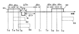
ここで、「送信回数」は、少なくとも1台の操作端末2a〜2cが制御信号を送信したときに、その制御信号が制御端末1a〜1cに受信されたか否かに関わらず1回と数えている。また、「スロット番号」の列の括弧内はそれぞれ制御部22の動作の結果を示し、「送信」は制御信号が送信され且つ確認信号が受信されたことを示し、「延期」は制御信号の送信が延期されたことを示す。まず、全ての操作端末2a〜2cで優先度は初期値である1となっているので、各操作端末2a〜2cの制御部22はそれぞれスロット番号n=13〜15の3通りのタイミングT13〜T15のうちの1つのタイミングで制御信号を送信部23に送信させようとする。表では第1の操作端末2aのみが最も早いスロット番号n=13のタイミングT13を選択しているので、第1の操作端末2aの制御部22がまず制御信号SC1を送信部23に送信させる。そして、より遅いスロット番号n=14,15のタイミングT14,T15をそれぞれ選択した他の2台の操作端末2b,2cでは、図9に示すように、それぞれ制御信号SC2,SC3を送信部23に送信させようとしたときに既に伝送線路3上に第1の操作端末2aの制御信号SC1が存在するので、制御部22は制御信号SC2,SC3の送信を延期するとともに、自身の優先度を1段階高くする。
Here, the “number of transmissions” is counted as one time regardless of whether or not the control signal is received by the
次に、第1の操作端末2aの制御信号に対する確認信号が各操作端末2a〜2cの信号検出部26に検出されたときには、第1の操作端末2aでは優先度が1であることにより制御部22が最も遅いスロット番号n=13〜15のタイミングT13〜T15から送信タイミングを選択するのに対し、他の操作端末2b,2cでは、優先度が2であるから、制御部22は第1の操作端末2aよりも確実に早いスロット番号n=10〜12のタイミングT10〜T12から送信タイミングを選択する。第3の操作端末2cで選択されたスロット番号n=12のタイミングT12よりも早いスロット番号n=10のタイミングT10が第2の操作端末2bで選択されたとすると、第2の操作端末2bの制御部22は送信部23に制御信号を送信させ、これに対する確認信号が信号検出部26に検出されたときに自身の優先度を最低値すなわち1にする。他の操作端末2a,2cでは、制御信号を送信しようとしたときには既に伝送線路3上に制御信号が存在するから、制御部22は制御信号の送信を延期し、自身の優先度を1段階高くする。ここにおいて、第1の操作端末2aの優先度は2となり、第3の操作端末2cの優先度は3となる。
Next, when a confirmation signal for the control signal of the
次に、第2の操作端末2bの制御信号に対する確認信号が各操作端末2a〜2cの信号検出部26に検出された後には、第3の操作端末2cでは優先度が3であって他の操作端末2a,2bよりも優先度が高いことにより、他の操作端末2a,2bよりも確実に早いタイミングT7〜T9から送信タイミングを選択する。当然、第3の操作端末2cでは制御部22が制御信号を送信させ、他の操作端末2a,2bでは制御部22が制御信号の送信を延期して自身の優先度を1段階高くする。
Next, after the confirmation signal for the control signal of the
以後、第1の操作端末2a、第2の操作端末2b、第3の操作端末2cの順に1台の操作端末2a〜2cのみで優先度が3となり、その他の操作端末では優先度が2以下となる。従って、制御信号は、確認信号が操作端末2a〜2cの信号検出部26に検出される毎に、優先度が3である1台の操作端末2a〜2cのみから送信され、制御信号同士の衝突は発生しない。
Thereafter, the priority is 3 only in the order of the
また、偶然同じタイミングが選択されて制御信号同士の衝突が発生した場合の動作を次表を用いて説明する。 The operation when the same timing is accidentally selected and a collision between the control signals occurs will be described with reference to the following table.
ここで、「スロット番号」の列の括弧内の「衝突」は制御信号が送信され且つ確認信号が受信されなかったことを示す。 Here, “collision” in parentheses in the column of “slot number” indicates that the control signal is transmitted and the confirmation signal is not received.
1回目の送信時に、第1の操作端末2aと第2の操作端末2bとで、それぞれ第3の操作端末2cで選択されたスロット番号n=14のタイミングT14より早いタイミングであって互いに同じスロット番号n=13のタイミングT13が選択されている。また、3回目の送信時には、第2の操作端末2bと第3の操作端末2cとで、それぞれ第1の操作端末2aで選択されたスロット番号n=14のタイミングT14より早いタイミングであって互いに同じスロット番号n=8のタイミングT8が選択されている。
During the first transmission, in a
この場合、図10に示すように制御信号SC1,SC2同士が伝送線路3上で衝突して制御端末1a〜1cには受信されないことにより、制御端末1a〜1cから確認信号は送信されない。従って、制御信号SC1,SC2を送信した各操作端末2a〜2cでは、タイムアウト時間ΔtOが経過しても確認信号SAが信号検出部26に検出されないから、それぞれ制御部22が自身の優先度を1段階高くするとともに、制御信号SC1,SC2を送信するためのスロット番号nを再度選択し、同じ制御信号の送信を試みる。
In this case, as shown in FIG. 10, the control signals SC1 and SC2 collide on the
つまり、制御信号が制御端末1a〜1cに受信されなければ優先度を高くすることになるから、衝突した制御信号を送信した操作端末2a〜2cに対応する照明負荷La〜Lcの照度変化が、他の操作端末2a〜2cに対応する照明負荷La〜Lcの照度変化よりも大きく遅れてしまうようなことがない。
That is, if the control signal is not received by the
また、制御信号同士の衝突が発生した2台の操作端末2a〜2cにおいて、その後に互いに異なるスロット番号nが選択されれば、より小さいスロット番号n(例えば10)を選択した操作端末2a〜2cの制御信号SC1のみが制御端末1a〜1cに受信されて該操作端末2a〜2cの優先度が1になる一方で、より大きいスロット番号n(例えば11)を選択した操作端末2a〜2cでは制御信号SC2の送信が延期されてさらに優先度が高くなる。つまり、優先度に差が生じるから、以後、これら2台の操作端末2a〜2cの間では制御信号同士の衝突は発生しなくなる。
Further, in the two
そして、同時に操作部21を操作された全ての操作端末2a〜2cがそれぞれ1回ずつ制御信号の送信に成功した送信回数5回目以降は、各操作端末2a〜2cの優先度は互いに異なることになるから、衝突が発生しなかった場合の動作と同様に、制御信号は、各操作端末2a〜2cから優先度の順に送信される。
Then, after the fifth transmission frequency in which all the
上記構成によれば、操作部21が操作されない操作端末2a〜2c及びこれに対応する制御端末1a〜1cは信号の送受信を行わないことにより、操作端末2a〜2c及び制御端末1a〜1cの数が多いときの操作端末2a〜2cへの操作に対する応答速度の低下を防止しつつ、複数の操作端末2a〜2cで同時にそれぞれ操作部21が操作された場合には、同時に操作部21を操作された各操作端末2a〜2cが優先順位の順に1回ずつ制御信号を送信することになるので、同時に操作部21を操作された各操作端末2a〜2cに対応する各照明負荷La〜Lcのうちの1個が他の照明負荷La〜Lcよりも先に一気に照度を変化させることが防止される。つまり、照明負荷La〜Lcの照度変化のタイミングのばらつきが抑えられるから、使用者に違和感を与えることがない。
According to the above configuration, the
(実施形態4)
本実施形態の基本構成は実施形態3と共通であるので、共通する部分については同じ符号を付して図示並びに説明を省略する。
(Embodiment 4)
Since the basic configuration of the present embodiment is the same as that of the third embodiment, common portions are denoted by the same reference numerals, and illustration and description thereof are omitted.
本実施形態は、複数の操作端末2a〜2cで同時にそれぞれ操作部21が操作されたときに、操作部21を操作された各操作端末2a〜2cで制御部22が互いに優先度を異ならせるようにしたものである。
In the present embodiment, when the
具体的には、実施形態1と同様に、操作端末2a〜2cを互いに信号線4a〜4dを介して接続し、各操作端末2a〜2cにそれぞれ操作端末間送信部24及び操作端末間受信部25を設けるとともに、操作端末2a〜2c毎に制御部22に優先順位を設定しておく。そして、信号線4a〜4dを通じた通信によって、複数の操作端末2a〜2cの各操作部21が同時に操作されたことが検知されたときには、優先順位の高い操作端末2a〜2cほど優先度の初期値が高くなるようにする。
Specifically, as in the first embodiment, the
例えば、第1の操作端末2aの操作部21と、第1の操作端末2aよりも優先順位が低く設定された第2の操作端末2bの操作部21とが同時に操作された場合を例に挙げて、次表を用いて説明する。
For example, a case where the
まず、第2の操作端末2bでは、制御部22は、同時に操作部21を操作された各操作端末2a,2bの中で自身が最も優先順位が低いことから、自身の優先度を1に設定する。また、第1の操作端末2aでは、同時に操作部21を操作された各操作端末2a,2bの中で自身よりも優先順位の低い操作端末2bが1台存在することから、自身の優先度を2に設定する。1回目の送信時、優先度の高い第1の操作端末2aでは、優先度の低い第2の操作端末2bで選択されるタイミングよりも確実に早いタイミングで、制御部22は送信部23に制御信号を送信させ、第2の操作端末2bでは制御部22は信号検出部26に第1の操作端末2aの制御信号が検出されることにより制御信号の送信を延期する。また、制御信号を送信した第1の操作端末2aでは、その後に確認信号が信号検出部26に検出されて制御部22が優先度を1にする。
First, in the
第1の操作端末2aの制御信号に対する確認信号が各操作端末2a,2bでそれぞれ信号検出部26に検出されたときには、1回目に制御信号の送信を延期した第2の操作端末2bの優先度が2になっているから、2回目の送信時、第2の操作端末2bでは、優先度の低い第1の操作端末2aで選択されるタイミングよりも確実に早いタイミングで、制御部22は送信部23に制御信号を送信させ、第1の操作端末2aでは制御部22は信号検出部26に第2の操作端末2bの制御信号が検出されることにより制御信号の送信を延期する。また、制御信号を送信した第2の操作端末2bでは、その後に確認信号が信号検出部26に検出されて制御部22が優先度を最低値の1にする。
When a confirmation signal for the control signal of the
以後は、常に各操作端末2a,2bの優先度が常に異なるから、第1の操作端末2aと第2の操作端末2bとが交互に制御信号を送信することになる。
Thereafter, since the priority of the
上記構成によれば、同時に操作部21を操作された複数の操作端末2a,2bの優先度が同じになることがないので、制御信号同士の衝突が発生しなくなるから、操作端末2a,2bへの操作に対する応答速度が実施形態3よりも向上する。
According to the above configuration, the priority of the plurality of
なお、実施形態1乃至3及び本実施形態において、操作端末2a〜2cと制御端末1a〜1cとを1対1に対応させる代わりに、操作端末2a〜2c又は制御端末1a〜1cのうちの1台が複数台分の機能を有して複数の操作端末2a〜2c又は制御端末1a〜1cに対応する構成としてもよい。
In the first to third embodiments and the present embodiment, instead of making the
1a〜1c 制御端末
2a〜2c 操作端末
3 伝送線路
4a〜4d 信号線
11 受信部
12 負荷制御部
13 制御部
15 送信部
21 操作部
22 制御部
23 送信部
24 操作端末間送信部
25 操作端末間受信部
26 信号検出部
La〜Lc 照明負荷
DESCRIPTION OF
Claims (5)
各操作端末はそれぞれ、照明負荷を調光制御するために操作される操作部と、操作部に加えられた操作に応じた制御信号を生成する制御部と、制御部が生成した制御信号を伝送線路に送信する制御送信部と、信号線を介して他の操作端末に接続され制御部の制御に応じた信号を他の操作端末に送信する操作端末間送信部と、信号線を介して他の操作端末に接続され他の操作端末からの信号を受信して制御部に入力する操作端末間受信部とを有し、
各制御端末はそれぞれ、伝送線路を通じて送信された制御信号を受信する受信部と、対応する操作端末からの制御信号が受信部に受信されると該制御信号に応じて照明負荷を調光制御する負荷制御部とを有し、
各操作端末の制御部は、制御信号を送信する前に操作端末間送信部を制御して制御信号の内容を示す予告信号を他の操作端末に送信させ、予告信号の送信中に他の操作端末からの予告信号が操作端末間受信部に受信された場合には、うち1台の操作端末においては、制御部は、予告信号を出力した他の全ての操作端末の制御信号と自身の制御信号との内容を含む合成制御信号を生成するとともに、少なくとも予告信号を出力した他の全ての操作端末と自身とにそれぞれ対応する各制御端末を全て含む複数の制御端末を対象として合成制御信号を制御送信部に送信させ、上記1台を除く他の操作端末においては、制御部は制御信号の送信を中止し、
制御端末の負荷制御部は、受信部に受信された合成制御信号から自らを対象とする制御信号の内容を検出し、該制御信号の内容に基いて照明負荷を調光制御することを特徴とする照明制御システム。 A lighting control system in which a plurality of control terminals each controlling a lighting load and a plurality of operation terminals corresponding to each control terminal and operated for dimming control of the lighting load are connected to a common transmission line,
Each operation terminal transmits an operation unit operated for dimming control of the lighting load, a control unit that generates a control signal according to an operation applied to the operation unit, and a control signal generated by the control unit A control transmission unit that transmits to the track, a transmission unit between operation terminals that is connected to another operation terminal via a signal line and transmits a signal according to the control of the control unit to the other operation terminal, and another via a signal line An inter-operation terminal receiving unit that is connected to the operation terminal and receives a signal from another operation terminal and inputs the signal to the control unit,
Each control terminal receives a control signal transmitted through the transmission line, and when the control signal from the corresponding operation terminal is received by the reception unit, dimming control is performed on the lighting load according to the control signal. A load control unit,
Before transmitting the control signal, the control unit of each operation terminal controls the inter-operation terminal transmission unit to transmit a warning signal indicating the content of the control signal to other operation terminals, and performs other operations during the transmission of the warning signal. When the notice signal from the terminal is received by the inter-operation terminal receiving unit, in one of the operation terminals, the control unit controls the control signals of all other operation terminals that output the notice signal and the control of itself. A composite control signal including the contents of the signal is generated, and at the same time, a composite control signal is generated for a plurality of control terminals including all the control terminals respectively corresponding to at least all other operation terminals that output the warning signal. In the control terminal other than the above one, the control unit stops transmission of the control signal.
The load control unit of the control terminal detects the content of the control signal intended for itself from the combined control signal received by the receiving unit, and performs dimming control of the lighting load based on the content of the control signal. Lighting control system.
各操作端末の制御部は、制御信号の送信を中止してから所定時間以内に合成制御信号が合成制御信号検出手段に検出されなかった場合には操作端末間送信部に再送要求信号を送信させ、
合成制御信号を制御送信部に送信させた後に、該合成制御信号に対応する再送要求信号が操作端末間受信部に受信されると、該合成制御信号を再び制御送信部に送信させることを特徴とする請求項1記載の照明制御システム。 Each operation terminal has a combined control signal detection means for detecting whether a combined control signal exists on the transmission line,
The control unit of each operation terminal causes the inter-operation terminal transmission unit to transmit a retransmission request signal when the combination control signal is not detected by the combination control signal detection unit within a predetermined time after stopping transmission of the control signal. ,
After transmitting the composite control signal to the control transmitter, when the retransmission request signal corresponding to the composite control signal is received by the inter-operation terminal receiver, the control signal is transmitted again to the control transmitter. The lighting control system according to claim 1.
各操作端末はそれぞれ、照明負荷を調光制御するために操作される操作部と、操作部に加えられた操作に応じた制御信号を生成する制御部と、制御部が生成した制御信号を伝送線路に送信する制御送信部と、伝送線路上の信号を検出する信号検出手段とを有し、
各制御端末はそれぞれ、伝送線路を通じて送信された制御信号を受信する受信部と、対応する操作端末からの制御信号が受信部に受信されると該制御信号に応じて照明負荷を段階的に調光制御する負荷制御部とを有し、
各操作端末の制御部は、制御信号の送信を試みる際に、信号検出手段に他の操作端末の制御信号が検出されている場合、又は信号検出手段に他の操作端末の制御信号が信号検出手段に検出されなくなった後に制御信号の検出に充分な時間である待機時間が経過する以前であった場合には、少なくとも信号検出手段に他の操作端末の制御信号が検出されなくなった後さらに待機時間が経過するまでは制御信号の送信を延期するものであって、
操作端末の制御部は、操作端末毎に保有するパラメータである優先度を保持し、自身の優先度が高いほど待機時間を短くし、
制御信号の送信を延期している操作端末が存在するときに連続して制御信号を送信することがないように、優先度を随時変更することを特徴とする照明制御システム。 A lighting control system in which a plurality of control terminals each controlling a lighting load and a plurality of operation terminals corresponding to each control terminal and operated for dimming control of the lighting load are connected to a common transmission line,
Each operation terminal transmits an operation unit operated for dimming control of the lighting load, a control unit that generates a control signal according to an operation applied to the operation unit, and a control signal generated by the control unit A control transmitter for transmitting to the line, and a signal detecting means for detecting a signal on the transmission line,
Each control terminal receives a control signal transmitted through the transmission line, and when the control signal from the corresponding operation terminal is received by the reception unit, the lighting load is adjusted stepwise according to the control signal. A load control unit for optical control,
When the control unit of each operation terminal tries to transmit a control signal, if the control signal of another operation terminal is detected by the signal detection unit, or the control signal of another operation terminal is detected by the signal detection unit If the waiting time, which is a sufficient time for detection of the control signal, has not passed since the detection is stopped by the means, at least after the control signal of the other operation terminal is no longer detected by the signal detection means Until the time has passed, the transmission of the control signal is postponed,
The control unit of the operation terminal holds the priority that is a parameter held for each operation terminal, and shortens the standby time as the own priority is higher,
A lighting control system, wherein priority is changed at any time so that a control signal is not continuously transmitted when there is an operation terminal that has postponed transmission of the control signal.
操作端末の制御部は、制御信号を制御送信部に送信させた後、確認信号の操作端末への到達に充分な時間であって待機時間よりも短い所定のタイムアウト時間内に信号検出手段に確認信号が検出されなかった場合には再度、制御信号の送信を試み、
他の操作端末の制御信号が信号検出手段に検出されたことで制御信号の送信を延期したとき、並びに制御信号を制御送信部に送信させてからタイムアウト時間内に確認信号が信号検出手段に検出されなかったときに、自身の優先度を上昇させ、
制御信号を制御送信部に送信させた後に該制御信号に対応する確認信号が信号検出手段に検出されたときには自身の優先度を最も低くすることを特徴とする請求項3記載の照明制御システム。 The control terminal has a transmission unit that transmits a confirmation signal to the operation terminal through the transmission line when a control signal from the corresponding operation terminal is received by the reception unit,
The control unit of the operation terminal transmits a control signal to the control transmission unit, and then confirms with the signal detection means within a predetermined time-out time that is sufficient for the confirmation signal to reach the operation terminal and is shorter than the standby time. If no signal is detected, try sending a control signal again,
When the control signal of another operation terminal is detected by the signal detection means, the confirmation signal is detected by the signal detection means when the transmission of the control signal is postponed and within the timeout period after the control signal is transmitted to the control transmission unit. If not, increase your priority,
4. The illumination control system according to claim 3, wherein when the confirmation signal corresponding to the control signal is detected by the signal detection means after the control signal is transmitted to the control transmission unit, the priority of the control signal is made lowest.
操作端末の制御部は、制御信号を制御送信部に送信させる前には制御信号の内容を示す予告信号を操作端末間送信部に送信させ、予告信号の送信中に他の操作端末の予告信号が操作端末間受信部に受信された場合には、予告信号を送信した各操作端末の優先度が全て異なるように自身の優先度を設定することを特徴とする請求項3又は請求項4記載の照明制御システム。 Each operation terminal is connected to another operation terminal via a signal line, and transmits to the other operation terminal via the signal line between an operation terminal transmission unit that transmits a signal according to the control of the control unit to the other operation terminal. An inter-operation terminal receiving unit that receives signals from other operation terminals and inputs the signals to the control unit;
The control unit of the operation terminal causes the inter-operation terminal transmission unit to transmit a warning signal indicating the content of the control signal before transmitting the control signal to the control transmission unit, and during the transmission of the warning signal, the warning signal of the other operation terminal 5. The priority level is set so that the priority levels of the respective operation terminals that have transmitted the warning signal are all different when received by the inter-operation terminal receiving unit. Lighting control system.
Priority Applications (1)
| Application Number | Priority Date | Filing Date | Title |
|---|---|---|---|
| JP2004107295A JP4029858B2 (en) | 2004-03-31 | 2004-03-31 | Lighting control system |
Applications Claiming Priority (1)
| Application Number | Priority Date | Filing Date | Title |
|---|---|---|---|
| JP2004107295A JP4029858B2 (en) | 2004-03-31 | 2004-03-31 | Lighting control system |
Publications (2)
| Publication Number | Publication Date |
|---|---|
| JP2005294032A true JP2005294032A (en) | 2005-10-20 |
| JP4029858B2 JP4029858B2 (en) | 2008-01-09 |
Family
ID=35326736
Family Applications (1)
| Application Number | Title | Priority Date | Filing Date |
|---|---|---|---|
| JP2004107295A Expired - Fee Related JP4029858B2 (en) | 2004-03-31 | 2004-03-31 | Lighting control system |
Country Status (1)
| Country | Link |
|---|---|
| JP (1) | JP4029858B2 (en) |
Cited By (3)
| Publication number | Priority date | Publication date | Assignee | Title |
|---|---|---|---|---|
| JP2007200200A (en) * | 2006-01-30 | 2007-08-09 | Sony Corp | Communication device, data processor, near field communication device, communication method, and program |
| JP2009238522A (en) * | 2008-03-26 | 2009-10-15 | Panasonic Electric Works Co Ltd | Wireless type light control system |
| JP2016522623A (en) * | 2013-05-07 | 2016-07-28 | セイン ピーティーワイ エルティーディー | Electrical control system and method |
-
2004
- 2004-03-31 JP JP2004107295A patent/JP4029858B2/en not_active Expired - Fee Related
Cited By (5)
| Publication number | Priority date | Publication date | Assignee | Title |
|---|---|---|---|---|
| JP2007200200A (en) * | 2006-01-30 | 2007-08-09 | Sony Corp | Communication device, data processor, near field communication device, communication method, and program |
| JP4561645B2 (en) * | 2006-01-30 | 2010-10-13 | ソニー株式会社 | Communication device, data processing device, proximity communication device, communication method, and program |
| US8559875B2 (en) | 2006-01-30 | 2013-10-15 | Sony Corporation | Communication device, data processing device, near field communication device, and method and program for communication |
| JP2009238522A (en) * | 2008-03-26 | 2009-10-15 | Panasonic Electric Works Co Ltd | Wireless type light control system |
| JP2016522623A (en) * | 2013-05-07 | 2016-07-28 | セイン ピーティーワイ エルティーディー | Electrical control system and method |
Also Published As
| Publication number | Publication date |
|---|---|
| JP4029858B2 (en) | 2008-01-09 |
Similar Documents
| Publication | Publication Date | Title |
|---|---|---|
| CN110024334B (en) | Input device for controlling lighting load, hub device and load control system | |
| US8755913B2 (en) | Lighting control network | |
| WO2011090814A1 (en) | Wireless ballast control unit | |
| KR101624749B1 (en) | Apparatus and method for controlling sleep mode in a communication system based on a packet | |
| JP5086770B2 (en) | Communication system and communication system in distribution board | |
| EP3578010B1 (en) | Distributed control of a lighting network | |
| JP6223459B2 (en) | Apparatus and method for interpreting reception control command | |
| JP4029858B2 (en) | Lighting control system | |
| JP2010514244A (en) | Selection of transmission and reception channels for communication between transmitter unit and receiver unit | |
| JP2004205143A (en) | Control system for multi-air-conditioner | |
| JP2002299072A (en) | Lighting control system | |
| US7599318B2 (en) | Technique for enabling communication between a communication device that performs an intermittent reception and a communication device that performs a continuous reception operation | |
| TWI470952B (en) | Communication system and transmission unit used therein | |
| JP6009734B2 (en) | Method for controlling the power consumption of a receiving unit | |
| US20060203714A1 (en) | Communication network | |
| JP2005135640A (en) | Communication system for lighting | |
| JP2006140764A (en) | Radio transmitter-receiver and light control system | |
| JP2008034911A (en) | Terminal control system | |
| JP6041233B2 (en) | Communication system and communication apparatus | |
| JP2005071839A (en) | Control system and lighting control system | |
| JP2009004321A (en) | Visible light communication system | |
| JP2008186604A (en) | Illumination apparatus with terminal function | |
| JP2020071936A (en) | Controller for illumination system, illumination system, and data transmission method for illumination system | |
| JP2001015272A (en) | Lighting system | |
| JP2009238522A (en) | Wireless type light control system |
Legal Events
| Date | Code | Title | Description |
|---|---|---|---|
| A621 | Written request for application examination |
Free format text: JAPANESE INTERMEDIATE CODE: A621 Effective date: 20060719 |
|
| A977 | Report on retrieval |
Free format text: JAPANESE INTERMEDIATE CODE: A971007 Effective date: 20070618 |
|
| A131 | Notification of reasons for refusal |
Free format text: JAPANESE INTERMEDIATE CODE: A131 Effective date: 20070626 |
|
| A521 | Written amendment |
Free format text: JAPANESE INTERMEDIATE CODE: A523 Effective date: 20070827 |
|
| TRDD | Decision of grant or rejection written | ||
| A01 | Written decision to grant a patent or to grant a registration (utility model) |
Free format text: JAPANESE INTERMEDIATE CODE: A01 Effective date: 20070925 |
|
| A61 | First payment of annual fees (during grant procedure) |
Free format text: JAPANESE INTERMEDIATE CODE: A61 Effective date: 20071008 |
|
| FPAY | Renewal fee payment (event date is renewal date of database) |
Free format text: PAYMENT UNTIL: 20101026 Year of fee payment: 3 |
|
| S533 | Written request for registration of change of name |
Free format text: JAPANESE INTERMEDIATE CODE: R313533 |
|
| FPAY | Renewal fee payment (event date is renewal date of database) |
Free format text: PAYMENT UNTIL: 20101026 Year of fee payment: 3 |
|
| R350 | Written notification of registration of transfer |
Free format text: JAPANESE INTERMEDIATE CODE: R350 |
|
| FPAY | Renewal fee payment (event date is renewal date of database) |
Free format text: PAYMENT UNTIL: 20101026 Year of fee payment: 3 |
|
| FPAY | Renewal fee payment (event date is renewal date of database) |
Free format text: PAYMENT UNTIL: 20111026 Year of fee payment: 4 |
|
| FPAY | Renewal fee payment (event date is renewal date of database) |
Free format text: PAYMENT UNTIL: 20111026 Year of fee payment: 4 |
|
| FPAY | Renewal fee payment (event date is renewal date of database) |
Free format text: PAYMENT UNTIL: 20121026 Year of fee payment: 5 |
|
| FPAY | Renewal fee payment (event date is renewal date of database) |
Free format text: PAYMENT UNTIL: 20131026 Year of fee payment: 6 |
|
| LAPS | Cancellation because of no payment of annual fees |