JP2005293956A - Surface light source device - Google Patents
Surface light source device Download PDFInfo
- Publication number
- JP2005293956A JP2005293956A JP2004105499A JP2004105499A JP2005293956A JP 2005293956 A JP2005293956 A JP 2005293956A JP 2004105499 A JP2004105499 A JP 2004105499A JP 2004105499 A JP2004105499 A JP 2004105499A JP 2005293956 A JP2005293956 A JP 2005293956A
- Authority
- JP
- Japan
- Prior art keywords
- light
- guide plate
- light guide
- light source
- source device
- Prior art date
- Legal status (The legal status is an assumption and is not a legal conclusion. Google has not performed a legal analysis and makes no representation as to the accuracy of the status listed.)
- Pending
Links
- 230000003287 optical effect Effects 0.000 claims abstract description 13
- 239000000463 material Substances 0.000 claims description 15
- 239000013543 active substance Substances 0.000 claims description 2
- 239000004973 liquid crystal related substance Substances 0.000 abstract description 18
- 239000000126 substance Substances 0.000 abstract description 4
- 239000002699 waste material Substances 0.000 abstract description 3
- 239000000758 substrate Substances 0.000 description 6
- 239000006260 foam Substances 0.000 description 4
- 238000009792 diffusion process Methods 0.000 description 3
- 229920001971 elastomer Polymers 0.000 description 3
- 239000002923 metal particle Substances 0.000 description 3
- 230000002093 peripheral effect Effects 0.000 description 3
- 229920000728 polyester Polymers 0.000 description 3
- 229910052709 silver Inorganic materials 0.000 description 3
- 239000004332 silver Substances 0.000 description 3
- JOYRKODLDBILNP-UHFFFAOYSA-N Ethyl urethane Chemical compound CCOC(N)=O JOYRKODLDBILNP-UHFFFAOYSA-N 0.000 description 2
- 230000000694 effects Effects 0.000 description 2
- 238000010030 laminating Methods 0.000 description 2
- 238000000034 method Methods 0.000 description 2
- 229920000098 polyolefin Polymers 0.000 description 2
- 229920002635 polyurethane Polymers 0.000 description 2
- 239000004814 polyurethane Substances 0.000 description 2
- 229920005989 resin Polymers 0.000 description 2
- 239000011347 resin Substances 0.000 description 2
- 238000010521 absorption reaction Methods 0.000 description 1
- 230000003247 decreasing effect Effects 0.000 description 1
- 238000001704 evaporation Methods 0.000 description 1
- 229920001821 foam rubber Polymers 0.000 description 1
- 230000035939 shock Effects 0.000 description 1
Images
Landscapes
- Liquid Crystal (AREA)
- Planar Illumination Modules (AREA)
Abstract
Description
本発明は、面光源装置に関するものである。 The present invention relates to a surface light source device.
面光源装置には、光源の配置位置により直下型とサイドライト型とあるが、本発明では一般的に多く用いられているサイドライト型面光源装置を用いて説明することにする。図5は、従来のサイドライト型面光源装置の基本構造を示す分解斜視図、図6は図5の矢視A方向から見た断面図である。1は光源で、例えば発光ダイオード(LED)である。光源1はフレキシブル基板8上に実装されており、前記光源1が実装されたフレキシブル基板8は、両面テープ7で導光板3の側端部(光入射面)に固定されている。
The surface light source device includes a direct type and a side light type depending on the arrangement position of the light source. In the present invention, a side light type surface light source device that is generally used will be described. FIG. 5 is an exploded perspective view showing a basic structure of a conventional sidelight type surface light source device, and FIG. 6 is a cross-sectional view seen from the direction of arrow A in FIG. Reference numeral 1 denotes a light source, for example, a light emitting diode (LED). The light source 1 is mounted on a
5はケースで、ケース5の底部に反射部材2を配置し、該反射部材2の上に導光板3が配置されている。該導光板3の光入射面側には光源1が配置され、該導光板3の光出射面側には光学部材4が配置されている。6は開口部発光エリア9を有するシャーシで、導光板3の光出射面側に前記開口部発光エリア9を対応させて被せられ、前記開口部発光エリア9の光出射面側周縁部位に防塵部材10が配置され、サイドライト型面光源装置が構成されている。
前記反射部材2はシート状に形成されたもので、高反射率を有する部材であり、例えば、ポリエステルやポリオレフィンあるいは樹脂シートに銀等の金属粒子を蒸着したものである。
The
前記光学部材4は数種のシート状部材が積層されたもので、図5および図6においては、導光板3の光出射面上に下から拡散シート、縦プリズムシート、横プリズムシートの順に積層され配置されている。
The optical member 4 is formed by laminating several kinds of sheet-like members. In FIGS. 5 and 6, a diffusion sheet, a vertical prism sheet, and a horizontal prism sheet are stacked in this order on the light output surface of the
前記防塵部材10は枠状に形成されたもので、防塵性・衝撃吸収性を有する部材である。前記防塵部材10は、例えば、発泡性ゴムや発泡性ポリウレタンを所望の形状に加工したものである。
The
前述のサイドライト型面光源装置は、ケース5内に収納された導光板3の光出射面に対向する面側(導光板3の下面側)に高反射率を有する反射部材2(上側反射面)を配置することにより光源1から出射された光は、反射部材2で上方向に反射されながら導光板3内を通過する。導光板3から立ち上げられた光は、光学部材4を通過することで出射方向が整えられて、シャーシ6の開口部発光エリア9から外部へ出射される。本装置は液晶表示装置の面光源装置として利用される(例えば、特許文献1参照)。
The above-described sidelight type surface light source device includes a reflective member 2 (upper reflective surface) having a high reflectance on the surface side (the lower surface side of the light guide plate 3) facing the light emitting surface of the
背景技術に示すサイドライト型面光源装置は、シャーシ6の光出斜面側で光開口部発光エリア9周縁部位(防塵部材10の矩形枠内部分)において、導光板3から出射した光の一部が、防塵部材10に吸収されたり、外部に透過して無駄になることがある。その結果、光が有効利用されずに液晶パネル上での輝度を上昇させられない要因や液晶コントラストを低下させる要因になるという問題があった。特に、小型面光源装置においては発光面積が小さい為に、光開口部発光エリアから出射される全光量の内で防塵部材に衝突する光量の比率が高くなるので、前述の問題はより問題視されていた。
In the sidelight type surface light source device shown in the background art, a part of light emitted from the
本発明は、光源より出射された光の無駄を無くし、出射光を有効に利用し、液晶パネル上での輝度値と液晶コントラストを向上させることを目的とする。 An object of the present invention is to eliminate the waste of light emitted from a light source, effectively use the emitted light, and improve the luminance value and the liquid crystal contrast on the liquid crystal panel.
少なくとも、光入射面と、該光入射面から入射された光を面状に出射する光出射面とを有する導光板と、前記導光板の光出射面に対向する面側に配置される反射部材と、前記導光板の光出射面側に配置される光学部材と、前記導光板の光入射面に向け光を出射する光源とをケース内に配置し、該ケース内に配置した前記導光板の光出射面上方に開口部を有するシャーシを被せて構成し、該シャーシの光出射面側には光反射性物質を含有する枠状の防塵部材を設けた面光源装置とする。 A light guide plate having at least a light incident surface and a light emitting surface that emits light incident from the light incident surface in a planar shape, and a reflecting member disposed on a surface facing the light emitting surface of the light guide plate An optical member disposed on the light emitting surface side of the light guide plate, and a light source that emits light toward the light incident surface of the light guide plate, and the light guide plate disposed in the case. The surface light source device is configured by covering a chassis having an opening above the light emitting surface, and providing a frame-shaped dustproof member containing a light reflective material on the light emitting surface side of the chassis.
前記導光板と、前記導光板の光出射面に対向する面側に配置される反射部材と、前記導光板の光出射面側に配置される光学部材と、前記導光板の光入射面に向け光を出射する光源とをケース内に配置し、該ケース内に配置した前記導光板の光出射面上方に開口部を有するシャーシを被せて構成し、該シャーシの光出射面側には光反射性物質を内側表面のみに付着させた枠状の防塵部材を設けた面光源装置とする。 The light guide plate, a reflecting member disposed on the surface facing the light exit surface of the light guide plate, an optical member disposed on the light exit surface side of the light guide plate, and toward the light incident surface of the light guide plate A light source that emits light is disposed in a case, and a chassis having an opening is placed over the light emitting surface of the light guide plate disposed in the case, and light reflection is performed on the light emitting surface side of the chassis. The surface light source device is provided with a frame-shaped dustproof member in which the active substance is attached only to the inner surface.
光出射面側の開口部発光エリア周縁部位に光反射性物質を含有する枠状の防塵部材を設けたので、光源より出射された光の無駄を無くし、出射光を有効に利用し、液晶パネル上での輝度値と液晶コントラストを向上させることができる。 Since a frame-shaped dust-proof member containing a light-reflective material is provided at the peripheral portion of the light emitting area of the opening on the light emitting surface side, the light emitted from the light source is eliminated, and the emitted light is used effectively. The brightness value and the liquid crystal contrast can be improved.
光出射面側の開口部発光エリア周縁部位に光反射性物質を内側表面のみに付着させた枠状の防塵部材を設けたので、光源より出射された光の無駄を無くし、出射光を有効に利用し、液晶パネル上での輝度値と液晶コントラストを向上させることができる。 A frame-shaped dust-proof member with a light-reflective material attached only to the inner surface is provided at the periphery of the light-emitting area on the light-emitting surface side, eliminating waste of light emitted from the light source and effectively using the emitted light It is possible to improve the luminance value and the liquid crystal contrast on the liquid crystal panel.
開口部発光エリア周縁部位に光反射性物質を含有する枠状の防塵部材を設けた構造とすることで、従来においては防塵部材自体に吸収されて無駄になっていた光を発光エリア内に戻し再利用することにより、液晶パネル上での輝度値と液晶コントラストの向上を実現した。 By adopting a structure in which a frame-shaped dust-proof member containing a light-reflective material is provided at the periphery of the light-emitting area of the opening, light that was previously absorbed by the dust-proof member itself and wasted is returned to the light-emitting area. By reusing it, the brightness value and liquid crystal contrast on the liquid crystal panel were improved.
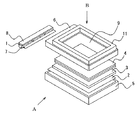
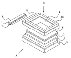
図1は、本発明の第一実施例で、サイドライト型面光源装置を示す分解斜視図である。図2は、図1の矢視A方向から見た断面図である。従来の構成と同様の部分については同一の符号を用いて説明する(以下、同様)。1は光源で、例えば発光ダイオード(LED)である。光源1はフレキシブル基板8上に実装されており、前記光源1が実装されたフレキシブル基板8は、両面テープ7で導光板3の側端部(光入射面)側に固定されている。
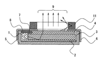
FIG. 1 is an exploded perspective view showing a side light type surface light source device according to a first embodiment of the present invention. 2 is a cross-sectional view seen from the direction of arrow A in FIG. Parts similar to those of the conventional configuration will be described using the same reference numerals (hereinafter the same). Reference numeral 1 denotes a light source, for example, a light emitting diode (LED). The light source 1 is mounted on a
5はケースで、ケース5の底部に反射部材2を配置し、該反射部材2の上に導光板3が配置されている。反射部材2はシート状の部材で、例えば、ポリエステルやポリオレフィンあるいは樹脂シートに銀等の金属粒子を蒸着したものである。前記導光板3の光入射面側には光源1が配置され、該導光板3の光出射面側には光学部材4が配置されている。該光学部材4は、例えば、導光板3の光出射面側から拡散シート、縦プリズムシート、横プリズムシートの順に各シート状部材が積層されて成るものである。6は開口部発光エリア9を有するシャーシで、導光板3の光出射面側に前記開口部発光エリア9を対応させて被せられ、前記開口部発光エリア9の光出射面側周縁部位に防塵部材11が配置され、サイドライト型面光源装置が構成されている。該防塵部材11は、例えば、発泡性ゴムや発泡性ポリウレタンに光反射性物質(不図示)を含有させて矩形枠状(本実施例では矩形であるが、本発明は枠の形状には関係なく適用できるものである。以下同じ)に形成したものである。
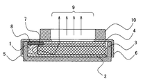
前記構成のサイドライト型面光源装置において、光源1から出射された光は、反射部材2で上方向に反射されながら導光板3内を通過する。導光板3から立ち上げられた光の多くは、光学部材4を通過することで光の出射方向が整えられて、開口部発光エリア9からサイドライト型面光源装置外部へ出射される。このとき、防塵部材11の矩形枠内を通過する出射光のうち、発光面から角度をもった一部の光は、防塵部材11に含有される光反射性物質により内向きに反射される。これにより反射された光は、防塵部材11の矩形枠内で反射を繰り返し再利用される。該構成により光の無駄を無くし、光量を増加するとともに液晶パネル上での輝度値と液晶コントラストを向上させることができる。
In the side light type surface light source device having the above configuration, the light emitted from the light source 1 passes through the
前記光反射性物質を含有する防塵部材11とは、発泡性ゴムや発泡性ウレタンの素地に光反射性物質を分散した物であり、光反射性物質により、防塵部材内部まで侵入した光を反射させることで、防塵部材自体に吸収される光量及び防塵部材を透過してしまう光量を大幅に減らせる利点がある。また、発泡体である前記防塵部材11は、面発光源装置を液晶パネル取付け時に押圧されることで発泡構造が密になるので、より光反射効果を高めるといえる。
The dust-
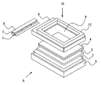
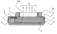
図3は、本発明の第二実施例で、サイドライト型面光源装置を示す分解斜視図である。図4は、図3の矢視A方向から見た断面図である。第二実施例では、第一実施例に示した矩形枠状の防塵部材の内側表面のみに光反射性物質層12aを付着させるように形成し、サイドライト型面光源装置を構成する。
FIG. 3 is an exploded perspective view showing a side light type surface light source device according to a second embodiment of the present invention. FIG. 4 is a cross-sectional view seen from the direction of arrow A in FIG. In the second embodiment, the light-reflecting
光源1から出射された光は、反射部材2で上方向に反射されながら導光板3内を通過する。導光板3から立ち上げられた光の多くは、光学部材4を通過することで光の出射方向が整えられて、開口部発光エリア9からサイドライト型面光源装置外部へ出射される。このとき、防塵部材12の矩形枠内(本実施例では矩形であるが、本発明は枠の形状には関係なく適用できるものである。以下同じ)を通過する出射光のうち、発光面から角度をもった一部の光は、防塵部材12の内側表面のみに付着された光反射性物質層12aにより内向きに反射される。これにより反射された光は、防塵部材12の矩形枠内で反射を繰り返し再利用される。該構成により光の無駄を無くし、光量を増加するとともに液晶パネル上での輝度値と液晶コントラストを向上させることができる。
The light emitted from the light source 1 passes through the
前記光反射性物質12aを内側表面のみに付着させた矩形状の防塵部材12は、発泡性ゴムや発泡性ウレタンの素地表面に白色反射ポリエステル層を付着させる方法や銀等の金属粒子を蒸着させる方法で形成される。発泡体である矩形状の該防塵部材12の内側表面に光反射性物質層12aを形成し、矩形状の防塵部材12の内側表面に衝突した光を反射させることで、防塵部材自体に吸収される光量や透過してしまう光量を減らせる利点がある。他にも、光反射性物質12aが矩形状の防塵部材12の必要箇所(内側表面)のみに付着しているので、該防塵部材12の他の特性(防塵性・衝撃吸収性)を損ないにくい利点がある。また、発泡体である該防塵部材12は、面発光源装置を液晶パネル取付け時に押圧されることで発泡構造が密になるので、より光反射効果を高めるといえる。
The rectangular dust-
1 光源
2 反射部材
3 導光板
4 光学部材
5 ケース
6 シャーシ
7 両面テープ
8 フレキシブル基板
9 開口部発光エリア
10 防塵部材
11 光拡散物質を含有した防塵部材
12 防塵部材
12a 光反射性物質層
DESCRIPTION OF SYMBOLS 1
Claims (2)
The light guide plate, a reflecting member disposed on the surface facing the light exit surface of the light guide plate, an optical member disposed on the light exit surface side of the light guide plate, and toward the light incident surface of the light guide plate A light source that emits light is disposed in a case, and a chassis having an opening is placed over the light emitting surface of the light guide plate disposed in the case, and light reflection is performed on the light emitting surface side of the chassis. The surface light source device according to claim 1, further comprising a frame-shaped dustproof member in which the active substance is attached only to the inner surface.
Priority Applications (1)
| Application Number | Priority Date | Filing Date | Title |
|---|---|---|---|
| JP2004105499A JP2005293956A (en) | 2004-03-31 | 2004-03-31 | Surface light source device |
Applications Claiming Priority (1)
| Application Number | Priority Date | Filing Date | Title |
|---|---|---|---|
| JP2004105499A JP2005293956A (en) | 2004-03-31 | 2004-03-31 | Surface light source device |
Publications (1)
| Publication Number | Publication Date |
|---|---|
| JP2005293956A true JP2005293956A (en) | 2005-10-20 |
Family
ID=35326673
Family Applications (1)
| Application Number | Title | Priority Date | Filing Date |
|---|---|---|---|
| JP2004105499A Pending JP2005293956A (en) | 2004-03-31 | 2004-03-31 | Surface light source device |
Country Status (1)
| Country | Link |
|---|---|
| JP (1) | JP2005293956A (en) |
Cited By (2)
| Publication number | Priority date | Publication date | Assignee | Title |
|---|---|---|---|---|
| CN101858524A (en) * | 2010-06-21 | 2010-10-13 | 李忠训 | LED panel light |
| KR101320656B1 (en) * | 2009-11-24 | 2013-10-23 | 엘지디스플레이 주식회사 | Backlight unit and liquid crystal display device using the same |
-
2004
- 2004-03-31 JP JP2004105499A patent/JP2005293956A/en active Pending
Cited By (2)
| Publication number | Priority date | Publication date | Assignee | Title |
|---|---|---|---|---|
| KR101320656B1 (en) * | 2009-11-24 | 2013-10-23 | 엘지디스플레이 주식회사 | Backlight unit and liquid crystal display device using the same |
| CN101858524A (en) * | 2010-06-21 | 2010-10-13 | 李忠训 | LED panel light |
Similar Documents
| Publication | Publication Date | Title |
|---|---|---|
| US10073215B2 (en) | Illumination device and display unit | |
| JP2024098979A (en) | Light-emitting device, display device and lighting device | |
| CN103375772A (en) | Lighting units, displays and lighting equipment | |
| JP2002231030A (en) | Surface lighting apparatus | |
| JP2009026614A (en) | Surface light-emitting device, and display | |
| US6765632B2 (en) | Spread illuminating apparatus with protection cover | |
| CN107726125B (en) | Backlight module | |
| JP2006216244A (en) | Led backlight and liquid crystal display device | |
| JP4829811B2 (en) | Illumination unit | |
| CN107533254A (en) | Light source device and display device | |
| KR20160117697A (en) | Display device | |
| WO2017138080A1 (en) | Display device | |
| JPWO2009118960A1 (en) | Liquid crystal display | |
| WO2015016048A1 (en) | Light source device, illumination device, and liquid crystal display device | |
| JP2005293956A (en) | Surface light source device | |
| CN101644860A (en) | Direct backlight module | |
| WO2017145240A1 (en) | Display device | |
| JP2011124026A (en) | Lighting unit, and display device equipped with the same | |
| JP4438539B2 (en) | Display device and planar light source device | |
| JP2006228523A (en) | Plane light source device and liquid crystal display | |
| WO2017104081A1 (en) | Display device | |
| JP2006024468A (en) | Surface light source device | |
| JP2005149848A (en) | Lighting device using light emitting diode | |
| JP2014059955A (en) | Lighting device and display device including the same | |
| JP5733519B2 (en) | Flexible planar lighting device |