JP2005293949A - Fuel gas production system and operation method thereof - Google Patents
Fuel gas production system and operation method thereof Download PDFInfo
- Publication number
- JP2005293949A JP2005293949A JP2004105155A JP2004105155A JP2005293949A JP 2005293949 A JP2005293949 A JP 2005293949A JP 2004105155 A JP2004105155 A JP 2004105155A JP 2004105155 A JP2004105155 A JP 2004105155A JP 2005293949 A JP2005293949 A JP 2005293949A
- Authority
- JP
- Japan
- Prior art keywords
- air
- amount
- combustion
- reforming
- gas
- Prior art date
- Legal status (The legal status is an assumption and is not a legal conclusion. Google has not performed a legal analysis and makes no representation as to the accuracy of the status listed.)
- Granted
Links
Images
Classifications
-
- Y—GENERAL TAGGING OF NEW TECHNOLOGICAL DEVELOPMENTS; GENERAL TAGGING OF CROSS-SECTIONAL TECHNOLOGIES SPANNING OVER SEVERAL SECTIONS OF THE IPC; TECHNICAL SUBJECTS COVERED BY FORMER USPC CROSS-REFERENCE ART COLLECTIONS [XRACs] AND DIGESTS
- Y02—TECHNOLOGIES OR APPLICATIONS FOR MITIGATION OR ADAPTATION AGAINST CLIMATE CHANGE
- Y02E—REDUCTION OF GREENHOUSE GAS [GHG] EMISSIONS, RELATED TO ENERGY GENERATION, TRANSMISSION OR DISTRIBUTION
- Y02E60/00—Enabling technologies; Technologies with a potential or indirect contribution to GHG emissions mitigation
- Y02E60/30—Hydrogen technology
- Y02E60/50—Fuel cells
-
- Y—GENERAL TAGGING OF NEW TECHNOLOGICAL DEVELOPMENTS; GENERAL TAGGING OF CROSS-SECTIONAL TECHNOLOGIES SPANNING OVER SEVERAL SECTIONS OF THE IPC; TECHNICAL SUBJECTS COVERED BY FORMER USPC CROSS-REFERENCE ART COLLECTIONS [XRACs] AND DIGESTS
- Y02—TECHNOLOGIES OR APPLICATIONS FOR MITIGATION OR ADAPTATION AGAINST CLIMATE CHANGE
- Y02P—CLIMATE CHANGE MITIGATION TECHNOLOGIES IN THE PRODUCTION OR PROCESSING OF GOODS
- Y02P70/00—Climate change mitigation technologies in the production process for final industrial or consumer products
- Y02P70/50—Manufacturing or production processes characterised by the final manufactured product
Landscapes
- Fuel Cell (AREA)
- Hydrogen, Water And Hydrids (AREA)
Abstract
【課題】オフガスタンクを不要にするとともに、簡単な構成で、燃焼装置に供給されるオフガス量の変動に良好に対応することを可能にする。
【解決手段】家庭用燃料ガス製造システム10は、燃焼触媒14を有して改質用燃料を蒸発させる蒸発装置16、改質装置18、空気供給装置50及び制御ECU74を備える。空気供給装置50は、空気コンプレッサ52と供給圧制御レギュレータ59とを備える。制御ECU74は、空気コンプレッサ52を駆動して必要空気量以上の空気を供給するとともに、圧力調整弁57、58及び供給圧制御レギュレータ59を制御して、改質装置18に供給される改質用空気の供給圧を一定に維持しつつ、PSA装置26からのオフガス放出量の変動に同期して、燃焼用空気量を変動させる。
【選択図】図1
An offgas tank is not required, and it is possible to satisfactorily cope with fluctuations in the amount of offgas supplied to a combustion device with a simple configuration.
A domestic fuel gas production system includes an evaporation device having a combustion catalyst and evaporating reforming fuel, a reforming device, an air supply device, and a control ECU. The air supply device 50 includes an air compressor 52 and a supply pressure control regulator 59. The control ECU 74 drives the air compressor 52 to supply more air than necessary, and controls the pressure regulating valves 57 and 58 and the supply pressure control regulator 59 to supply the reforming device 18 with reforming. While maintaining the air supply pressure constant, the amount of combustion air is varied in synchronization with the variation in the amount of offgas released from the PSA device 26.
[Selection] Figure 1
Description
本発明は、含水素燃料を改質することにより、水素リッチな燃料ガスを生成する燃料ガス製造システム及びその運転方法に関する。 The present invention relates to a fuel gas production system that generates hydrogen-rich fuel gas by reforming a hydrogen-containing fuel, and an operation method thereof.
例えば、天然ガス等の炭化水素燃料やメタノール等のアルコールを含む含水素燃料を改質して水素含有ガス(改質ガス)を得、この水素含有ガスを燃料ガスとして燃料電池等に供給する水素製造装置(燃料ガス製造システム)が採用されている。 For example, a hydrogen-containing gas (reformed gas) is obtained by reforming a hydrocarbon fuel such as natural gas or an alcohol such as methanol to obtain a hydrogen-containing gas (reformed gas). A production apparatus (fuel gas production system) is employed.
この種の水素製造装置では、天然ガスや都市ガス等の炭化水素燃料を水蒸気改質して高濃度な水素リッチガスである水素含有ガスを製造するとともに、PSA(Pressure Swing Adsorption)装置を介して前記水素含有ガスから高純度水素を圧力吸着により分離している。 In this type of hydrogen production apparatus, a hydrocarbon fuel such as natural gas or city gas is steam reformed to produce a hydrogen-containing gas that is a high-concentration hydrogen-rich gas, and through the PSA (Pressure Swing Adsorption) apparatus, High purity hydrogen is separated from the hydrogen-containing gas by pressure adsorption.
具体的には、水蒸気改質された水素含有ガスには、主成分である水素ガスの他、CO、CO2、H2O、CH4等の不要物が含まれている。そこで、PSA装置は、例えば、3塔の吸着塔を備えており、各吸着塔に、吸着、減圧、均圧、ブロークダウン及びパージ工程からなるサイクリック運転を行わせることにより、高純度水素を取り出す一方、他の成分をオフガス(排ガス)として放出するように構成している。 Specifically, the steam-reformed hydrogen-containing gas contains unnecessary substances such as CO, CO 2 , H 2 O, and CH 4 in addition to the main component hydrogen gas. Therefore, the PSA apparatus is equipped with, for example, three adsorption towers, and high purity hydrogen is produced by causing each adsorption tower to perform a cyclic operation including adsorption, decompression, pressure equalization, brokedown, and purge steps. On the other hand, other components are discharged as off-gas (exhaust gas).
PSA装置から放出されるオフガスは、通常、オフガスタンクに一時的に貯蔵され、水素製造用改質器のバーナ(燃焼装置)に燃焼用燃料として供給されている。その際、オフガスタンクには、各吸着塔からオフガスが断続的に供給されるため、前記オフガスタンクに圧力変動が惹起する。しかしながら、オフガスタンクの圧力変動は、改質器やPSA装置等の運転に影響を及ぼすとともに、バーナの燃焼状態を変動させてしまうため、前記圧力変動を抑える必要がある。 The off-gas released from the PSA device is usually temporarily stored in an off-gas tank and supplied as a combustion fuel to a burner (combustion device) of a reformer for hydrogen production. At that time, off gas is intermittently supplied from the respective adsorption towers to the off gas tank, which causes pressure fluctuations in the off gas tank. However, the pressure fluctuation in the off-gas tank affects the operation of the reformer, the PSA device, and the like and also changes the combustion state of the burner. Therefore, it is necessary to suppress the pressure fluctuation.
そこで、例えば、特許文献1に開示されているオフガス圧力の制御方法が知られている。この制御方法では、図6に示すように、PSA装置から改質器燃焼部に連通するオフガス流路1の途上に、オフガスタンク2が配置されている。オフガスタンク2の出口側導管には、圧力計3が配置されるとともに、この圧力計3の下流には、該圧力計3で計測される実圧力によって開度が変更可能なオフガス流量調整バルブ4が設けられている。このオフガス流量調整バルブ4の下流には、流量計5が配置されている。
Therefore, for example, a method for controlling the off-gas pressure disclosed in Patent Document 1 is known. In this control method, as shown in FIG. 6, an
そこで、オフガスタンク2の最小圧力を基準とし、前記オフガスタンク2の出口側導管に配置されたオフガス流量調整バルブ4の開度を、その全開に対して所定の微小刻みで増減させている。これにより、オフガスタンク2からのオフガスの圧力変動を抑え、該オフガスを改質器燃焼部のバーナへ安定して供給することができる、としている。
Therefore, with the minimum pressure of the
しかしながら、オフガスタンク2は、その機能を有効に発揮させるために、PSA装置の数倍の大きさが必要になり、水素製造装置全体が相当に大型化する。特に、家庭用水素製造装置では、設置スペースが狭小であり、上記大型のオフガスタンク2を備えた水素製造装置の採用が困難であるという問題がある。
However, the
本発明はこの種の問題を解決するものであり、オフガスタンクを不要にするとともに、簡単な構成で、燃焼装置に供給されるオフガス量の変動に良好に対応することが可能な燃料ガス製造システム及びその運転方法を提供することを目的とする。 The present invention solves this type of problem, and eliminates the need for an offgas tank, and with a simple configuration, a fuel gas production system capable of well responding to fluctuations in the amount of offgas supplied to the combustion device And an operation method thereof.
本発明は、含水素燃料を改質して改質ガスを得る改質装置と、前記改質ガスから不要物を除去して水素リッチな燃料ガスを精製するPSA装置と、前記PSA装置からの排ガスを燃焼させる燃焼装置と、少なくとも前記燃焼装置に空気を供給する圧縮機を有するとともに、前記圧縮機の下流に空気量調整機構を設ける空気供給装置と、少なくとも前記燃焼装置に必要な空気量以上の空気を供給するよう前記圧縮機を制御し、且つ前記PSA装置からの排ガス量の変動に同期して、前記燃焼装置に供給される空気量が変動するよう前記空気量調整機構を制御する制御装置とを備えている。 The present invention relates to a reformer that reforms hydrogen-containing fuel to obtain a reformed gas, a PSA device that purifies hydrogen-rich fuel gas by removing unnecessary substances from the reformed gas, and a PSA device. A combustion apparatus that combusts exhaust gas; an air supply apparatus that includes at least a compressor that supplies air to the combustion apparatus; and an air amount adjustment mechanism downstream of the compressor; and at least an air amount that is necessary for the combustion apparatus For controlling the compressor so as to supply the air, and controlling the air amount adjusting mechanism so that the amount of air supplied to the combustion device varies in synchronization with the variation in the amount of exhaust gas from the PSA device Device.
また、空気供給装置は、燃焼装置に燃焼用空気を供給する燃焼用空気流路と、改質装置に改質用空気を供給する改質用空気流路とを備え、制御装置は、前記燃焼装置及び前記改質装置に必要な空気量以上の空気を供給するよう前記圧縮機を制御し、且つ前記改質装置に供給される改質用空気の流量又は供給圧を一定に維持しつつ、前記PSA装置からの排ガス量の変動に同期して、前記燃焼装置に供給される燃焼用空気量が変動するよう前記空気量調整機構を制御することが好ましい。 The air supply device includes a combustion air flow path for supplying combustion air to the combustion device, and a reforming air flow channel for supplying reforming air to the reforming device, and the control device includes the combustion air flow path. Controlling the compressor so as to supply more air than necessary for the apparatus and the reformer, and maintaining a constant flow rate or supply pressure of the reforming air supplied to the reformer, It is preferable to control the air amount adjusting mechanism so that the amount of combustion air supplied to the combustion device fluctuates in synchronization with the fluctuation of the exhaust gas amount from the PSA device.
さらに、本発明は、含水素燃料を改質して改質ガスを得る改質装置と、前記改質ガスから不要物を除去して水素リッチな燃料ガスを精製するPSA装置と、前記PSA装置からの排ガスを燃焼させる燃焼装置と、少なくとも前記燃焼装置に空気を供給する圧縮機を有するとともに、前記圧縮機の下流に空気量調整機構を設ける空気供給装置とを備える燃料ガス製造システムの運転方法である。 Furthermore, the present invention provides a reformer that reforms a hydrogen-containing fuel to obtain a reformed gas, a PSA device that purifies hydrogen-rich fuel gas by removing unnecessary substances from the reformed gas, and the PSA device A method for operating a fuel gas production system, comprising: a combustion device that combusts exhaust gas from a fuel; and an air supply device that includes at least a compressor that supplies air to the combustion device and that has an air amount adjustment mechanism downstream of the compressor It is.
そこで、圧縮機が制御されることにより、少なくとも燃焼装置に必要な空気量以上の空気が供給されるとともに、空気量調整機構が制御されることにより、PSA装置からの排ガス量の変動に同期して、前記燃焼装置に供給される空気量が変動される。 Therefore, by controlling the compressor, at least air exceeding the amount of air necessary for the combustion device is supplied, and by controlling the air amount adjustment mechanism, it is synchronized with fluctuations in the exhaust gas amount from the PSA device. Thus, the amount of air supplied to the combustion device is varied.
さらにまた、圧縮機の作用下に、燃焼装置及び改質装置に必要な空気量以上の空気を供給する一方、空気量調整機構の作用下に、前記改質装置に供給される改質用空気の供給圧を一定に維持しつつ、PSA装置からの排ガス量の変動に同期して、前記燃焼装置に供給される燃焼用空気量を変動させることが好ましい。 Furthermore, the air for reforming supplied to the reforming device under the action of the air amount adjusting mechanism while supplying air exceeding the air amount necessary for the combustion device and the reforming device under the action of the compressor. It is preferable to vary the amount of combustion air supplied to the combustion device in synchronism with the variation in the amount of exhaust gas from the PSA device while maintaining the supply pressure at a constant.
本発明では、PSA装置からの排ガス量の変動に同期して、燃焼装置に供給される空気量が変動されるため、前記PSA装置の脈動によって排ガスの供給量が減少した場合に、空気の供給量も減少する。このため、排ガスの供給量に対して燃焼用空気の供給量が相対的に増加することによる燃焼装置の温度低下を阻止することができ、この燃焼装置で未燃焼成分が発生することを良好に回避することが可能になる。これにより、外部に未燃焼成分が直接排出されることがなく、清浄な排ガスを確実に得ることができる。 In the present invention, the amount of air supplied to the combustion device is changed in synchronization with the change in the amount of exhaust gas from the PSA device. Therefore, when the supply amount of exhaust gas decreases due to the pulsation of the PSA device, the supply of air The amount is also reduced. For this reason, it is possible to prevent a decrease in the temperature of the combustion device due to a relative increase in the supply amount of combustion air with respect to the supply amount of exhaust gas, and it is favorable that unburned components are generated in this combustion device It can be avoided. Thereby, unburned components are not directly discharged to the outside, and clean exhaust gas can be obtained reliably.
さらに、排ガス量の変動に対応して圧縮機の出力を変動させないことも可能である。これによれば、圧縮機、例えば、コンプレッサの耐久負荷が高くなることがなく、しかも出力上昇時に過剰な電力を消費することを阻止することが可能になり、経済的である。 Furthermore, it is possible not to change the output of the compressor in response to the fluctuation of the exhaust gas amount. According to this, the endurance load of the compressor, for example, the compressor does not increase, and it is possible to prevent excessive power consumption when the output increases, which is economical.
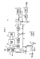
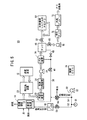
図1は、本発明の第1の実施形態に係る運転方法を実施するための家庭用燃料ガス製造システム(燃料ガス製造システム)10の概略構成図である。 FIG. 1 is a schematic configuration diagram of a household fuel gas production system (fuel gas production system) 10 for carrying out an operation method according to a first embodiment of the present invention.
家庭用燃料ガス製造システム10は、燃焼触媒(燃焼装置)14を有して改質用燃料を蒸発させる蒸発装置16を備える。蒸発装置16の下流には、改質用燃料を改質して改質ガスを得る改質装置18が配設されるとともに、前記蒸発装置16と前記改質装置18との間には、前記蒸発した改質用燃料を前記改質ガスと熱交換して加熱する熱交換装置20が介装される。熱交換装置20の下流には、熱交換された改質ガスを冷却する冷却装置22が配設されるとともに、この冷却装置22の下流には、冷却された前記改質ガスをガス成分と水分とに分離する気液分離装置24が配設される。
The household fuel
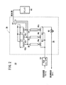
気液分離装置24の下流には、水分が分離された改質ガスを圧縮してPSA装置26に供給するPSAコンプレッサ28が配設される。図2に示すように、PSA装置26は、PSAコンプレッサ28にそれぞれ接続可能な、例えば、3塔式圧力スイング吸着装置を構成しており、吸着塔30、32及び34を備える。各吸着塔30〜34の出入口の一端には、弁36a〜36cが設けられるとともに、前記弁36a〜36cを介して前記吸着塔30〜34がオフガス流路38に接続される。オフガス流路38は、燃焼触媒14に接続されるとともに、このオフガス流路38の途上には、弁40が配設される。
A
各吸着塔30〜34の出入口の他端には、弁42a〜42cが設けられるとともに、前記吸着塔30〜34は、弁44を介してタンク46に連通可能である。図1に示すように、タンク46は、管路48を介してオフガス流路38に連通する一方、前記オフガス流路38には、空気供給装置50が接続される。
空気供給装置50は、燃焼用空気供給機構と改質用空気供給機構とを兼用する圧縮機、例えば、空気コンプレッサ52を備える。この空気コンプレッサ52には、燃焼用空気流路54と、改質用空気流路56とが接続される。燃焼用空気流路54は、オフガス流路38の途上に連通して燃焼触媒14に燃焼用空気を供給するとともに、前記燃焼用空気流路54には、圧力調整弁(空気量調整機構)57が配設される。改質用空気流路56には、圧力調整弁(空気量調整機構)58及びインジェクタ60が配設されており、蒸発装置16に改質用燃料及び水と共に改質用空気を供給する。
The
空気供給装置50は、空気コンプレッサ52の下流に配置された供給圧制御レギュレータ(空気量調整機構)59を備えるとともに、前記供給圧制御レギュレータ59に近接して圧力検出センサ61が配設される。
The
タンク46は、流量調整又は圧力調整を行う弁62を介して固体高分子型燃料電池スタック(PEFC)64内の燃料ガス流路(図示ぜず)に連通可能であるとともに、流量制御弁66及び高圧コンプレッサ68を介して高圧タンク70に連通可能である。この高圧タンク70は、水素ディスペンサ72に水素を供給することにより、前記水素ディスペンサ72を介して図示しない燃料電池自動車(FC自動車)に水素を供給することができる。燃料電池スタック64は、定置型であり、水素(燃料)循環システムを備えている。
The
家庭用燃料ガス製造システム10は、各補機類と通信及び制御を行うとともに、特に第1の実施形態では、燃焼触媒14及び改質装置18(少なくとも燃焼触媒14)に必要な空気量以上の空気を供給するよう空気コンプレッサ52を制御し、且つ前記改質装置18に供給される改質用空気の供給圧を一定に維持しつつ、PSA装置26からの排ガス量の変動に同期して、前記燃焼触媒14に供給される燃焼用空気量が変動するよう圧力調整弁57、58を制御する制御部として、例えば、制御ECU(Electronic Control Unit)74を備える。なお、供給圧制御レギュレータ59に代えて圧力調整弁(図示せず)を使用する際には、制御ECU74がこの圧力調整弁を制御する。
The home fuel
このように構成される家庭用燃料ガス製造システム10の動作について、燃料ガス発生方法との関連で以下に説明する。
The operation of the domestic fuel
家庭用燃料ガス製造システム10では、制御ECU74の起動信号がオンされて、空気コンプレッサ52が所定の回転数で運転を開始される。このため、燃焼用空気及び改質用空気は、それぞれ燃焼用空気流路54及び改質用空気流路56を介して燃焼触媒14及び蒸発装置16に供給される。
In the household fuel
改質用空気流路56において、空気コンプレッサ52から送られる改質用空気は、圧力調整弁58により圧力差が低減(振幅が縮小)され、さらにインジェクタ60を介して略一定の圧力に調整された後、蒸発装置16に送られる。
In the reforming
蒸発装置16には、上記の改質用空気の他に改質用燃料及び水が供給される一方、燃焼触媒14では、燃焼用空気及び必要に応じてタンク46から水素が供給されて燃焼が行われ、前記改質用燃料が蒸発する。蒸発した改質用燃料は、熱交換装置20を通って改質装置18に供給されるとともに、この改質装置18から排出される改質ガスとの間で熱交換を行って昇温される。
In addition to the above reforming air, reforming fuel and water are supplied to the
改質装置18では、改質用燃料中の、例えば、メタン、空気中の酸素及び水蒸気によって、酸化反応であるCH4+2O2→CO2+2H2O(発熱反応)と、燃料改質反応であるCH4+2H2O→CO2+4H2(吸熱反応)とが同時に行われる(オートサーマル方式)。
In the
改質装置18から熱交換装置20に供給された改質ガスは、改質用燃料との間で熱交換を行った後、冷却装置22により冷却されて、気液分離装置24に供給される。この気液分離装置24で水分が分離された改質ガスは、PSAコンプレッサ28で圧縮されてPSA装置26に供給される。
The reformed gas supplied from the
PSA装置26では、図2に示すように、改質ガスが吸着塔30、32及び34に選択的に供給される。その際、PSA装置26では、例えば、吸着塔30で吸着工程、吸着塔32で減圧工程、及び吸着塔34でパージ工程が行われる。このため、吸着塔30内で水素以外の成分が吸着されて、高濃度の水素(水素リッチ)を含む燃料ガスがタンク46に供給される。
In the
さらに、吸着塔30で吸着工程、吸着塔32で均圧工程、及び吸着塔34で均圧工程を経た後、前記吸着塔30で吸着工程、前記吸着塔32でブローダウン工程、及び吸着塔34で昇圧工程が実施される。従って、吸着塔30でのブローダウン工程によるオフガスは、弁36aの開放作用下にオフガス流路38に供給され、弁40を通って燃焼触媒14に供給される。
Further, after the adsorption process in the
上記のように、吸着塔30、32及び34では、吸着工程、減圧工程、パージ工程、均圧工程及びブローダウン工程が選択的に行われることにより、水素リッチな燃料ガスがタンク46に供給される。一方、排ガスであるオフガスが、弁36a〜36cの開閉作用下に、オフガス流路38を介して燃焼触媒14に連続的に供給される。
As described above, in the adsorption towers 30, 32, and 34, the adsorption process, the decompression process, the purge process, the pressure equalization process, and the blowdown process are selectively performed, so that the hydrogen-rich fuel gas is supplied to the
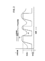
この場合、第1の実施形態では、図3に示すように、改質装置18に必要な改質用空気の流量は、略一定しているのに対して、燃焼触媒14に供給される燃焼用空気の流量は、PSA装置26の圧力脈動によって増減するオフガス放出量に対応して変動している(必要流量80参照)。
In this case, in the first embodiment, as shown in FIG. 3, the flow rate of the reforming air necessary for the
そこで、制御ECU74は、空気供給装置50を構成する空気コンプレッサ52を制御し、改質用空気及び燃焼用空気の必要流量80以上の空気を、出力変動(又は、出力一定)制御によって供給する(空気コンプレッサ吐出流量82参照)。
Therefore, the
さらに、制御ECU74は、圧力調整弁58を一定の開度に維持して蒸発装置16から改質装置18に供給される改質用空気の供給圧を一定に維持しつつ、PSA装置26からのオフガス放出量の変動に同期して、圧力調整弁57を調整する。その際、燃焼用空気の供給圧の変動に伴って余剰圧力が発生すると、供給圧制御レギュレータ59により、余剰圧力分の空気が外部に放出される。なお、供給圧制御レギュレータ59から放出される余分な空気は、大気に放出され、あるいはシステム内で有効に使用される。
Further, the
このように、第1の実施形態では、PSA装置26の圧力脈動により増減するオフガスの放出量に同期して圧力調整弁57を制御し、燃焼用空気の供給量を増減している。従って、燃焼触媒14に供給されるオフガス量が減少する際に、燃焼用空気の供給量が減少し、前記燃焼触媒14の温度が低下することを阻止することができる。
As described above, in the first embodiment, the
これにより、燃焼触媒14において、オフガスの未燃焼成分が発生することを有効に阻止し、この未燃焼部分が直接外部に配設されることがなく、清浄な排ガスを確実に得ることが可能になる。
This effectively prevents off-gas unburned components from being generated in the
さらに、第1の実施形態では、空気コンプレッサ52は、常に、必要空気流量以上の出力で運転されており、PSA装置26からのオフガス放出量の増減に正確に対応して、出力変動させないことも可能である。この場合、空気コンプレッサ52の耐久負荷が高くなることがなく、しかも出力上昇時に過剰な電力を消費することを阻止することができ、経済的であるという効果が得られる。
Furthermore, in the first embodiment, the
さらにまた、PSA装置26からのオフガス放出量の変動に対応して、圧力調整弁57を制御して燃焼用空気の供給量を増減する際には、供給圧制御レギュレータ59により余分な空気が外部に放出されて、改質用空気流路56に導入されることがない。
Furthermore, when the
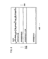
これにより、圧力検出センサ61により検出される改質用空気の供給圧は、常に一定圧力に維持されており、改質装置18に供給される改質用空気の流量が変動することはない。すなわち、図4に示すように、改質用空気の供給圧は、略一定圧力に維持され、改質装置18の触媒温度が変動することがなく、安定した改質ガスを確実に得ることができるという利点がある。
Thereby, the supply pressure of the reforming air detected by the
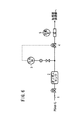
図5は、本発明の第2の実施形態に係る運転方法を実施するための家庭用燃料ガス製造システム(燃料ガス製造システム)90の概略構成図である。なお、第1の実施形態に係る家庭用燃料ガス製造システム10と同一の構成要素には同一の参照符号を付して、その詳細な説明は省略する。
FIG. 5 is a schematic configuration diagram of a household fuel gas production system (fuel gas production system) 90 for carrying out the operating method according to the second embodiment of the present invention. In addition, the same referential mark is attached | subjected to the component same as the household fuel
家庭用燃料ガス製造システム90は、空気供給装置92を備えており、この空気供給装置92を構成する燃焼用空気流路54には、三方向制御バルブ94が配設される。この空気供給装置92では、第1の実施形態の空気供給装置50を構成する供給圧制御レギュレータ59を用いていない。
The domestic fuel
このように構成される第2の実施形態では、三方向制御バルブ94を制御することにより、燃焼触媒14に供給される燃焼用空気の流量を、PSA装置26から排出されるオフガス放出量の増減に対応して増減させるとともに、余剰の酸素を外部に放出することができる。
In the second embodiment configured as described above, by controlling the three-
このため、燃焼触媒14に供給されるオフガス量が減少する際に、燃焼用空気の供給量を減少させることが可能になり、しかも改質装置18に供給される改質用空気の供給量を一定に維持することができる等、第1の実施形態と同様の効果が得られる。
For this reason, when the amount of off-gas supplied to the
なお、第2の実施形態では、燃焼用空気流路54に三方向制御バルブ94を配設しているが、改質用空気流路56に圧力調整弁58に代替して前記三方向制御バルブ94を配設してもよい。
In the second embodiment, the three-
また、第1及び第2の実施形態では、燃焼装置として燃焼触媒14を用いて説明したが、これに限定されるものではなく、例えば、バーナ等の種々の加熱手段を用いてもよい。
In the first and second embodiments, the
10、90…家庭用燃料ガス製造システム 14…燃焼触媒
16…蒸発装置 18…改質装置
20…熱交換装置 22…冷却装置
24…気液分離装置 26…PSA装置
28…PSAコンプレッサ 30、32、34…吸着塔
36a〜36c、42a〜42c、44、62…弁
38…オフガス流路 40、57、58…圧力調整弁
46…タンク 50、92…空気供給装置
52…空気コンプレッサ 54…燃焼用空気流路
56…改質用空気流路 59…供給圧制御レギュレータ
60…インジェクタ 61…圧力検出センサ
64…燃料電池スタック 70…高圧タンク
74…制御ECU 94…三方向制御バルブ
DESCRIPTION OF
Claims (4)
前記改質ガスから不要物を除去して水素リッチな燃料ガスを精製するPSA装置と、
前記PSA装置からの排ガスを燃焼させる燃焼装置と、
少なくとも前記燃焼装置に空気を供給する圧縮機を有するとともに、前記圧縮機の下流に空気量調整機構を設ける空気供給装置と、
少なくとも前記燃焼装置に必要な空気量以上の空気を供給するよう前記圧縮機を制御し、且つ前記PSA装置からの排ガス量の変動に同期して、前記燃焼装置に供給される空気量が変動するよう前記空気量調整機構を制御する制御装置と、
を備えることを特徴とする燃料ガス製造システム。 A reformer for reforming hydrogen-containing fuel to obtain reformed gas;
A PSA device for purifying hydrogen-rich fuel gas by removing unnecessary substances from the reformed gas;
A combustion device for burning the exhaust gas from the PSA device;
An air supply device having at least a compressor for supplying air to the combustion device, and an air amount adjusting mechanism downstream of the compressor;
The compressor is controlled so as to supply at least air necessary for the combustion device, and the amount of air supplied to the combustion device fluctuates in synchronization with fluctuations in the amount of exhaust gas from the PSA device. A control device for controlling the air amount adjusting mechanism,
A fuel gas production system comprising:
前記改質装置に改質用空気を供給する改質用空気流路と、
を備え、
前記制御装置は、前記燃焼装置及び前記改質装置に必要な空気量以上の空気を供給するよう前記圧縮機を制御し、且つ前記改質装置に供給される改質用空気の流量又は供給圧を一定に維持しつつ、前記PSA装置からの排ガス量の変動に同期して、前記燃焼装置に供給される燃焼用空気量が変動するよう前記空気量調整機構を制御することを特徴とする燃料ガス製造システム。 The fuel gas production system according to claim 1, wherein the air supply device includes a combustion air flow path for supplying combustion air to the combustion device;
A reforming air flow path for supplying reforming air to the reforming device;
With
The control device controls the compressor so as to supply air exceeding the amount of air necessary for the combustion device and the reforming device, and the flow rate or supply pressure of the reforming air supplied to the reforming device. The air amount adjusting mechanism is controlled so that the amount of combustion air supplied to the combustion device fluctuates in synchronism with fluctuations in the amount of exhaust gas from the PSA device while maintaining the fuel pressure constant. Gas production system.
前記圧縮機を制御することにより、少なくとも前記燃焼装置に必要な空気量以上の空気を供給する工程と、
前記空気量調整機構を制御することにより、前記PSA装置からの排ガス量の変動に同期して、前記燃焼装置に供給される空気量を変動させる工程と、
を有することを特徴とする燃料ガス製造システムの運転方法。 A reformer that reforms a hydrogen-containing fuel to obtain a reformed gas, a PSA device that removes unnecessary substances from the reformed gas to purify a hydrogen-rich fuel gas, and burns exhaust gas from the PSA device An operating method of a fuel gas production system, comprising: a combustion device; and an air supply device that includes a compressor that supplies air to at least the combustion device, and an air amount adjusting mechanism downstream of the compressor,
Supplying at least air more than the amount of air necessary for the combustion device by controlling the compressor; and
Varying the amount of air supplied to the combustion device in synchronism with fluctuations in the amount of exhaust gas from the PSA device by controlling the air amount adjustment mechanism;
A method for operating a fuel gas production system, comprising:
4. The operation method according to claim 3, wherein air exceeding the amount of air necessary for the combustion device and the reforming device is supplied under the action of the compressor, and the reforming is performed under the action of the air amount adjustment mechanism. The amount of combustion air supplied to the combustion device is changed in synchronization with the change in the amount of exhaust gas from the PSA device while maintaining the flow rate or supply pressure of the reforming air supplied to the quality device constant. A method for operating a fuel gas production system.
Priority Applications (1)
| Application Number | Priority Date | Filing Date | Title |
|---|---|---|---|
| JP2004105155A JP4612322B2 (en) | 2004-03-31 | 2004-03-31 | Fuel gas production system and operation method thereof |
Applications Claiming Priority (1)
| Application Number | Priority Date | Filing Date | Title |
|---|---|---|---|
| JP2004105155A JP4612322B2 (en) | 2004-03-31 | 2004-03-31 | Fuel gas production system and operation method thereof |
Publications (2)
| Publication Number | Publication Date |
|---|---|
| JP2005293949A true JP2005293949A (en) | 2005-10-20 |
| JP4612322B2 JP4612322B2 (en) | 2011-01-12 |
Family
ID=35326669
Family Applications (1)
| Application Number | Title | Priority Date | Filing Date |
|---|---|---|---|
| JP2004105155A Expired - Fee Related JP4612322B2 (en) | 2004-03-31 | 2004-03-31 | Fuel gas production system and operation method thereof |
Country Status (1)
| Country | Link |
|---|---|
| JP (1) | JP4612322B2 (en) |
Cited By (6)
| Publication number | Priority date | Publication date | Assignee | Title |
|---|---|---|---|---|
| CN101629085A (en) * | 2008-09-24 | 2010-01-20 | 何巨堂 | Method for designing driving system for circulating hydrogen compressor of hydrocarbon hydrogenation device |
| JP2010067534A (en) * | 2008-09-12 | 2010-03-25 | Toyota Motor Corp | Fuel cell system and control method of fuel cell system |
| WO2015008837A1 (en) * | 2013-07-19 | 2015-01-22 | 大阪瓦斯株式会社 | Method for hydrogen production by pressure swing adsorption |
| JP2015503352A (en) * | 2012-01-05 | 2015-02-02 | 中▲イン長▼江国▲際▼新能源投▲資▼有限公司 | Method and system for controlling and treating pests using smoke from a biomass power plant in a sealed space |
| WO2020100454A1 (en) * | 2018-11-12 | 2020-05-22 | 東京瓦斯株式会社 | Hydrogen production apparatus |
| WO2020100453A1 (en) * | 2018-11-12 | 2020-05-22 | 東京瓦斯株式会社 | Hydrogen production apparatus |
Citations (5)
| Publication number | Priority date | Publication date | Assignee | Title |
|---|---|---|---|---|
| JPH01251561A (en) * | 1988-03-30 | 1989-10-06 | Mitsubishi Electric Corp | Control of combustor for fuel cell reformer |
| JP2002068708A (en) * | 2000-09-04 | 2002-03-08 | Fuji Electric Co Ltd | Hydrogen generator and its operation method |
| JP2002121003A (en) * | 2000-10-13 | 2002-04-23 | Toyota Motor Corp | Raw material input control of reformer |
| JP2003128401A (en) * | 2001-10-19 | 2003-05-08 | Fuji Electric Co Ltd | Hydrogen generator and its operation method |
| JP2005289704A (en) * | 2004-03-31 | 2005-10-20 | Honda Motor Co Ltd | Fuel gas production system and method for stopping the same |
-
2004
- 2004-03-31 JP JP2004105155A patent/JP4612322B2/en not_active Expired - Fee Related
Patent Citations (5)
| Publication number | Priority date | Publication date | Assignee | Title |
|---|---|---|---|---|
| JPH01251561A (en) * | 1988-03-30 | 1989-10-06 | Mitsubishi Electric Corp | Control of combustor for fuel cell reformer |
| JP2002068708A (en) * | 2000-09-04 | 2002-03-08 | Fuji Electric Co Ltd | Hydrogen generator and its operation method |
| JP2002121003A (en) * | 2000-10-13 | 2002-04-23 | Toyota Motor Corp | Raw material input control of reformer |
| JP2003128401A (en) * | 2001-10-19 | 2003-05-08 | Fuji Electric Co Ltd | Hydrogen generator and its operation method |
| JP2005289704A (en) * | 2004-03-31 | 2005-10-20 | Honda Motor Co Ltd | Fuel gas production system and method for stopping the same |
Cited By (10)
| Publication number | Priority date | Publication date | Assignee | Title |
|---|---|---|---|---|
| JP2010067534A (en) * | 2008-09-12 | 2010-03-25 | Toyota Motor Corp | Fuel cell system and control method of fuel cell system |
| CN101629085A (en) * | 2008-09-24 | 2010-01-20 | 何巨堂 | Method for designing driving system for circulating hydrogen compressor of hydrocarbon hydrogenation device |
| JP2015503352A (en) * | 2012-01-05 | 2015-02-02 | 中▲イン長▼江国▲際▼新能源投▲資▼有限公司 | Method and system for controlling and treating pests using smoke from a biomass power plant in a sealed space |
| WO2015008837A1 (en) * | 2013-07-19 | 2015-01-22 | 大阪瓦斯株式会社 | Method for hydrogen production by pressure swing adsorption |
| JP2015038015A (en) * | 2013-07-19 | 2015-02-26 | 大阪瓦斯株式会社 | Pressure swing adsorption type hydrogen production method |
| US9675927B2 (en) | 2013-07-19 | 2017-06-13 | Osaka Gas Co., Ltd. | Method for hydrogen production by pressure swing adsorption |
| WO2020100454A1 (en) * | 2018-11-12 | 2020-05-22 | 東京瓦斯株式会社 | Hydrogen production apparatus |
| WO2020100453A1 (en) * | 2018-11-12 | 2020-05-22 | 東京瓦斯株式会社 | Hydrogen production apparatus |
| JP2020079168A (en) * | 2018-11-12 | 2020-05-28 | 東京瓦斯株式会社 | Hydrogen production equipment |
| JP2020079169A (en) * | 2018-11-12 | 2020-05-28 | 東京瓦斯株式会社 | Hydrogen production apparatus |
Also Published As
| Publication number | Publication date |
|---|---|
| JP4612322B2 (en) | 2011-01-12 |
Similar Documents
| Publication | Publication Date | Title |
|---|---|---|
| JP4098167B2 (en) | Fuel gas generation method and apparatus | |
| US7011693B2 (en) | Control of a hydrogen purifying pressure swing adsorption unit in fuel processor module for hydrogen generation | |
| JP2008529218A (en) | Fuel cell power plant | |
| JP2010212141A (en) | Fuel cell generator | |
| JP4167997B2 (en) | Fuel gas production apparatus and starting method thereof | |
| JP4612322B2 (en) | Fuel gas production system and operation method thereof | |
| JP2015017023A (en) | Hydrogen production equipment | |
| JP2005251603A (en) | Abnormal stopping method for fuel gas production equipment | |
| JP4180534B2 (en) | Fuel gas production apparatus and operation method thereof | |
| JP5032025B2 (en) | Liquid fuel solid polymer battery system and method for stopping the same | |
| JP4032031B2 (en) | Fuel gas production equipment | |
| JP7129330B2 (en) | Hydrogen production device, hydrogen production method, and operation program | |
| JP4041085B2 (en) | Fuel gas production system and method for stopping the same | |
| JP4088262B2 (en) | Starting method of fuel gas production apparatus | |
| JP3867082B2 (en) | Method for stopping household fuel gas production equipment | |
| JP4139338B2 (en) | Fuel gas production equipment | |
| JP2005293959A (en) | Hydrogen gas production power generation system and operation method thereof | |
| JP4357979B2 (en) | Starting method of fuel gas production apparatus | |
| JP6751365B2 (en) | Hydrogen production equipment | |
| JP2009080944A (en) | Fuel cell power generator | |
| JP6549300B1 (en) | Hydrogen production apparatus, hydrogen production method, and operation program | |
| JP2007518664A (en) | Reformate cooling system for use in subsystems for fuel processing | |
| JP2005239500A (en) | Fuel gas filling method | |
| JP2009107876A (en) | Hydrogen generator and fuel cell power generation system | |
| JP2006156117A (en) | Fuel cell system |
Legal Events
| Date | Code | Title | Description |
|---|---|---|---|
| A621 | Written request for application examination |
Free format text: JAPANESE INTERMEDIATE CODE: A621 Effective date: 20061128 |
|
| A711 | Notification of change in applicant |
Free format text: JAPANESE INTERMEDIATE CODE: A711 Effective date: 20061218 |
|
| A977 | Report on retrieval |
Free format text: JAPANESE INTERMEDIATE CODE: A971007 Effective date: 20100831 |
|
| TRDD | Decision of grant or rejection written | ||
| A01 | Written decision to grant a patent or to grant a registration (utility model) |
Free format text: JAPANESE INTERMEDIATE CODE: A01 Effective date: 20100928 |
|
| A01 | Written decision to grant a patent or to grant a registration (utility model) |
Free format text: JAPANESE INTERMEDIATE CODE: A01 |
|
| A61 | First payment of annual fees (during grant procedure) |
Free format text: JAPANESE INTERMEDIATE CODE: A61 Effective date: 20101015 |
|
| FPAY | Renewal fee payment (event date is renewal date of database) |
Free format text: PAYMENT UNTIL: 20131022 Year of fee payment: 3 |
|
| R150 | Certificate of patent or registration of utility model |
Ref document number: 4612322 Country of ref document: JP Free format text: JAPANESE INTERMEDIATE CODE: R150 Free format text: JAPANESE INTERMEDIATE CODE: R150 |
|
| R250 | Receipt of annual fees |
Free format text: JAPANESE INTERMEDIATE CODE: R250 |
|
| R250 | Receipt of annual fees |
Free format text: JAPANESE INTERMEDIATE CODE: R250 |
|
| S111 | Request for change of ownership or part of ownership |
Free format text: JAPANESE INTERMEDIATE CODE: R313117 |
|
| R350 | Written notification of registration of transfer |
Free format text: JAPANESE INTERMEDIATE CODE: R350 |
|
| R250 | Receipt of annual fees |
Free format text: JAPANESE INTERMEDIATE CODE: R250 |
|
| R250 | Receipt of annual fees |
Free format text: JAPANESE INTERMEDIATE CODE: R250 |
|
| R250 | Receipt of annual fees |
Free format text: JAPANESE INTERMEDIATE CODE: R250 |
|
| R250 | Receipt of annual fees |
Free format text: JAPANESE INTERMEDIATE CODE: R250 |
|
| R250 | Receipt of annual fees |
Free format text: JAPANESE INTERMEDIATE CODE: R250 |
|
| R250 | Receipt of annual fees |
Free format text: JAPANESE INTERMEDIATE CODE: R250 |
|
| R250 | Receipt of annual fees |
Free format text: JAPANESE INTERMEDIATE CODE: R250 |
|
| R250 | Receipt of annual fees |
Free format text: JAPANESE INTERMEDIATE CODE: R250 |
|
| LAPS | Cancellation because of no payment of annual fees |