JP2005293934A - Power generator - Google Patents
Power generator Download PDFInfo
- Publication number
- JP2005293934A JP2005293934A JP2004104688A JP2004104688A JP2005293934A JP 2005293934 A JP2005293934 A JP 2005293934A JP 2004104688 A JP2004104688 A JP 2004104688A JP 2004104688 A JP2004104688 A JP 2004104688A JP 2005293934 A JP2005293934 A JP 2005293934A
- Authority
- JP
- Japan
- Prior art keywords
- gas
- reformer
- chamber
- fuel
- temperature
- Prior art date
- Legal status (The legal status is an assumption and is not a legal conclusion. Google has not performed a legal analysis and makes no representation as to the accuracy of the status listed.)
- Granted
Links
Images

Classifications
-
- Y—GENERAL TAGGING OF NEW TECHNOLOGICAL DEVELOPMENTS; GENERAL TAGGING OF CROSS-SECTIONAL TECHNOLOGIES SPANNING OVER SEVERAL SECTIONS OF THE IPC; TECHNICAL SUBJECTS COVERED BY FORMER USPC CROSS-REFERENCE ART COLLECTIONS [XRACs] AND DIGESTS
- Y02—TECHNOLOGIES OR APPLICATIONS FOR MITIGATION OR ADAPTATION AGAINST CLIMATE CHANGE
- Y02E—REDUCTION OF GREENHOUSE GAS [GHG] EMISSIONS, RELATED TO ENERGY GENERATION, TRANSMISSION OR DISTRIBUTION
- Y02E60/00—Enabling technologies; Technologies with a potential or indirect contribution to GHG emissions mitigation
- Y02E60/30—Hydrogen technology
- Y02E60/50—Fuel cells
Landscapes
- Fuel Cell (AREA)
- Hydrogen, Water And Hydrids (AREA)
Abstract
【課題】 予備改質器と、予備改質器内に導入する燃料ガスと水蒸気を加熱するにあたって、加熱のための資源を消費することがない発電装置を実現する。
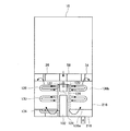
【解決手段】 前処理ユニット110は、燃料ガス昇温室124と、水蒸発室128と、燃料ガスと水蒸気を混合させる混合ガス混合室132と、予備改質器114とを有している。燃焼ガス導出管58から燃焼ガスが導入され、前処理ユニット110内が加熱される。燃焼ガスを利用して、予備改質器114内の触媒温度を最適温度に維持することができ、予備改質器114に供給する、燃料ガスと水蒸気の混合ガスを良好に予加熱することができる。
【選択図】 図1PROBLEM TO BE SOLVED: To realize a pre-reformer and a power generator that does not consume heating resources when heating a fuel gas and water vapor introduced into the pre-reformer.
A pre-processing unit 110 includes a fuel gas temperature raising chamber 124, a water evaporation chamber 128, a mixed gas mixing chamber 132 for mixing fuel gas and water vapor, and a pre-reformer 114. Combustion gas is introduced from the combustion gas outlet pipe 58 and the inside of the pretreatment unit 110 is heated. Using the combustion gas, the catalyst temperature in the pre-reformer 114 can be maintained at an optimum temperature, and the mixed gas of fuel gas and steam supplied to the pre-reformer 114 can be preheated well. it can.
[Selection] Figure 1
Description
本発明は、固体酸化物を利用する燃料電池によって発電する装置に関する。 The present invention relates to an apparatus for generating electricity by a fuel cell using a solid oxide.
固体酸化物型燃料電池では、炭素数2以上の炭化水素(エタン、プロパン、ブタン等)を含有する都市ガスやLPガス等の燃料ガスを用いる。しかし、炭素数2以上の炭化水素を燃料電池セルに供給すると、燃料極で炭素が析出したり、配管や燃料電池セルの燃料ガス通路内に析出した炭素が溜まって閉塞したりして燃料電池を劣化させるおそれがある。従って、炭素数2以上の炭化水素を含有する燃料ガスを用いる場合、炭素数2以上の炭化水素の予備改質を行って、水素と、炭素数1のメタンや一酸化炭素となった予備改質ガスを用いる。 In the solid oxide fuel cell, a fuel gas such as city gas or LP gas containing hydrocarbons having 2 or more carbon atoms (ethane, propane, butane, etc.) is used. However, when hydrocarbons having 2 or more carbon atoms are supplied to the fuel cell, carbon is deposited at the fuel electrode, or carbon deposited in the fuel gas passages of the piping and the fuel cell is accumulated and blocked. May deteriorate. Therefore, when using a fuel gas containing hydrocarbons having 2 or more carbon atoms, pre-reformation of hydrocarbons having 2 or more carbon atoms is carried out so that hydrogen, methane or carbon monoxide having 1 carbon atom are preliminarily modified. Use quality gas.
特許文献1に記載の固体酸化物形燃料電池用予備改質器では、水蒸気改質法による予備改質の技術が開示されている。水蒸気改質法では、予備改質器に水と燃料ガスを供給し、予備改質器を加熱することによって改質に最適な温度(約400℃)を維持して反応を促進する。特許文献1の技術では、燃料ガスの予備改質に改質ガスのオフガス(発電反応に利用されきらなかったガス)や、有酸素ガスのオフガスや、あるいは、これらの両者を燃焼させて得られる燃焼ガスを利用して予備改質器を加熱することによって予備改質器での改質反応を促進させる。この技術では、高温である改質ガスのオフガスや有酸素ガスのオフガスや燃焼ガスの熱が予備改質器の加熱に利用されている。
特許文献1には、燃料ガスと水蒸気を予め加熱して混合させてから予備改質器内に導入する技術の記載がある。
予備改質温度に達していない燃料ガスと水蒸気を予備改質器内に導入すると、予備改質器内を通過しながら燃料ガスと水蒸気は温度上昇するが、燃料ガスと水蒸気の温度が予備改質温度まで加熱されるまでに通過する予備改質触媒の領域では、改質反応は行われないこととなって、予備改質触媒が無駄になってしまう。従って、特許文献1のように、燃料ガスと水蒸気も予加熱してから予備改質器に供給するのが好ましい。特許文献1では、燃料ガスと水蒸気を予加熱するための加熱源を説明していないが、400℃以上まで加熱するために、通常の技術では、バーナ等で燃料ガス等を燃焼させる。しかし、このような加熱に必要な熱エネルギーは大きく、燃料ガス等の資源を多く消費してしまう。発電効率を高めるために多くの資源を消費してしまうのは、省エネルギーの面で回避したい。
本発明の発電装置では、予備改質器と、予備改質器内に導入する燃料ガスと水蒸気を加熱するにあたって、加熱のための資源を消費することがない発電装置を実現する。
Patent Document 1 describes a technique in which fuel gas and water vapor are heated and mixed in advance and then introduced into a pre-reformer.
When fuel gas and water vapor that have not reached the pre-reforming temperature are introduced into the pre-reformer, the temperature of the fuel gas and water vapor increases while passing through the pre-reformer, but the temperature of the fuel gas and water vapor is pre-modified. In the region of the pre-reforming catalyst that passes until it is heated to the material temperature, the reforming reaction is not performed, and the pre-reforming catalyst is wasted. Therefore, as in Patent Document 1, it is preferable to preheat the fuel gas and water vapor before supplying them to the pre-reformer. Patent Document 1 does not describe a heating source for preheating fuel gas and water vapor. However, in order to heat the fuel gas and water vapor to 400 ° C. or higher, in a normal technique, the fuel gas or the like is burned by a burner or the like. However, the heat energy required for such heating is large and consumes a lot of resources such as fuel gas. We want to avoid consuming a lot of resources to improve power generation efficiency in terms of energy saving.
The power generator of the present invention realizes a pre-reformer and a power generator that does not consume heating resources when heating the fuel gas and water vapor introduced into the pre-reformer.
本発明は、燃料ガスを昇温して水蒸気と混合する昇温蒸発混合器と、昇温蒸発混合器で得られた混合ガスを予備改質ガスに改質する予備改質器と、予備改質ガスを改質ガスに改質する改質器と、改質ガスを受入れて発電する固体酸化物型の燃料電池セルと、燃料電池セルで利用されなかった改質ガスを燃焼する燃焼部と、燃焼部で得られた燃焼ガスを昇温蒸発混合器と予備改質器の周囲を通過させる燃焼ガス導出路とを有していることを特徴としている。
昇温蒸発混合器と予備改質器の「周囲」とは、これらの部材の「外部近傍」を示している。そして、燃焼ガスを昇温蒸発混合器と予備改質器の周囲を通過させる燃焼ガス導出路とは、燃焼ガスをこれらの部材の外部近傍を通過させる導出路を示しており、燃焼ガスが通過する際に、昇温蒸発混合器と予備改質器の夫々の内部のガスと燃焼ガスが混合されることのない導出路を意味している。例えば、燃焼ガスを、予備改質器を貫通させる(予備改質器の内部を通過する)燃焼ガス導出路であっても、予備改質器内のガスと燃焼ガス導出路内の燃焼ガスとが混合されない構成であれば、この燃焼ガス導出路を、燃焼ガスを予備改質器の外部近傍を通過させる導出路と捉えることができ、この燃料ガス導出路は、本発明の、燃焼ガスを昇温蒸発混合器と予備改質器の周囲を通過させる燃焼ガス導出路に含まれる。
予備改質器に未加熱の燃料ガスと水をそれぞれ導入し、予備改質器内で加熱する方式では、燃料ガスと水の温度が触媒温度の最適温度まで上昇する前に通過する触媒の領域で改質反応が行われることはなく、非効率的である。燃料ガスと水をバーナ等の加熱装置によって予加熱して予備改質器に導入するのでは、発電効率を高めるために燃料ガス等の資源の消費を増やすこととなり、発電装置全体のエネルギー効率は低下する。
本発明では、燃料ガスを昇温して水蒸気と混合する昇温蒸発混合器と、昇温蒸発混合器で得られた混合ガスを予備改質ガスに改質する予備改質器とを有している。改質器で予備改質ガスを改質ガスに改質し、この改質ガスを燃料電池セルに供給する。燃料電池セルで発電に利用されきらなかった改質ガスは燃焼部で燃焼されるが、本発明では、このとき得られる燃焼ガスが昇温蒸発混合器と予備改質器の周囲を通過する構成となっている。この構成によれば、昇温蒸発混合器と予備改質器は燃焼ガスの熱によって加熱される。燃焼ガスは高温であり、予備改質器を加熱し、予備改質触媒の温度を最適温度に維持することが可能であり、さらに、予備改質器内に導入するための、燃料ガスを昇温して水蒸気と混合した混合ガスを生成することができる。従って、燃料ガス等の資源を消費することなく、予備改質器と、予備改質器内に導入する燃料ガスと水蒸気を加熱することができ、熱効率を向上させることができる。
なお、昇温蒸発混合器は、予備改質器と同一容器に収容されていてもよいし、予備改質器とは別の単一容器内に全部が集合して収容されていてもよい。また、昇温蒸発混合器は、予備改質器とは別に設けられ、且つ機能別に別個に設けられていてもよい。昇温蒸発混合器は、単なるパイプから構成されていてもよい。
The present invention includes a temperature-evaporating mixer that raises the temperature of a fuel gas and mixes it with water vapor, a pre-reformer that reforms the mixed gas obtained by the temperature-evaporating mixer into a pre-reformed gas, and a preliminary modification. A reformer that reforms the gas into a reformed gas, a solid oxide fuel cell that receives the reformed gas and generates power, and a combustion unit that burns the reformed gas that was not used in the fuel cell. Further, the present invention is characterized in that it has a combustion gas outlet passage through which the combustion gas obtained in the combustion section passes through the temperature-evaporating mixer and the periphery of the pre-reformer.
“Ambient” of the temperature rising evaporator and the pre-reformer indicates “outside vicinity” of these members. The combustion gas lead-out path for passing the combustion gas around the temperature-evaporating mixer and the pre-reformer indicates a lead-out path through which the combustion gas passes near the outside of these members. In this case, it means a lead-out path in which the gas and the combustion gas inside the temperature-evaporating mixer and the pre-reformer are not mixed. For example, even if the combustion gas is a combustion gas lead-out path that passes through the pre-reformer (passes through the inside of the pre-reformer), the gas in the pre-reformer and the combustion gas in the combustion gas lead-out path If the fuel gas is not mixed, this combustion gas lead-out path can be regarded as a lead-out path through which the combustion gas passes through the vicinity of the outside of the pre-reformer. It is included in the combustion gas lead-out path that passes around the temperature rising evaporator and the pre-reformer.
In the system in which unheated fuel gas and water are respectively introduced into the pre-reformer and heated in the pre-reformer, the area of the catalyst that passes before the temperature of the fuel gas and water rises to the optimum temperature of the catalyst temperature. Thus, the reforming reaction is not performed and is inefficient. When fuel gas and water are preheated by a heating device such as a burner and introduced into a pre-reformer, the consumption of resources such as fuel gas is increased in order to increase power generation efficiency. descend.
In the present invention, a temperature rising evaporation mixer that raises the temperature of the fuel gas and mixes it with water vapor, and a pre-reformer that reforms the mixed gas obtained by the temperature rising evaporation mixer into a pre-reformed gas. ing. The reformer reforms the pre-reformed gas into reformed gas, and supplies the reformed gas to the fuel cell. The reformed gas that could not be used for power generation in the fuel cell is burned in the combustion section. In the present invention, the combustion gas obtained at this time passes around the temperature-evaporating mixer and the pre-reformer. It has become. According to this configuration, the temperature rising evaporator and the pre-reformer are heated by the heat of the combustion gas. The combustion gas is hot and can heat the pre-reformer to maintain the temperature of the pre-reforming catalyst at the optimum temperature. A mixed gas that is warmed and mixed with water vapor can be produced. Therefore, the pre-reformer, the fuel gas introduced into the pre-reformer and the water vapor can be heated without consuming resources such as fuel gas, and the thermal efficiency can be improved.
Note that the temperature-evaporating mixer may be accommodated in the same container as the pre-reformer, or may be accommodated in a single container separate from the pre-reformer. Moreover, the temperature rising evaporation mixer may be provided separately from the pre-reformer, and may be provided separately for each function. The temperature rising evaporation mixer may be composed of a simple pipe.
本発明では、昇温蒸発混合器は、燃料ガスを昇温する昇温室と、水を蒸発させる蒸発室と、昇温室で昇温した燃料ガスと蒸発室で蒸発した水蒸気を混合する混合室を有することが好ましい。
昇温蒸発混合器が、機能別に別個の室に分かれているため、燃焼ガスを夫々の室の周囲に導いて満遍なく加熱させることができ、夫々の機能を良好に発揮させることができる。
In the present invention, the temperature rising evaporation mixer includes a temperature raising chamber for raising the temperature of the fuel gas, an evaporation chamber for evaporating water, and a mixing chamber for mixing the fuel gas heated in the temperature raising chamber and the water vapor evaporated in the evaporation chamber. It is preferable to have.
Since the temperature-evaporating mixer is divided into separate chambers according to functions, the combustion gas can be guided to the surroundings of the respective chambers to be heated uniformly, and the respective functions can be exhibited well.
本発明では、燃焼ガス導出路は、燃焼ガスを、予備改質器、混合室、蒸発室、昇温室の順序で、それぞれの周囲に導くことが好ましい。
燃焼ガスが、まず、最も高温を必要とする予備改質器の周囲を通過する構成であれば、予備改質器内の触媒温度を最適温度まで十分に加熱することができる。予備改質器を通過して温度低下した燃焼ガスが、混合室、蒸発室、昇温室の順に通過する構成であれば、混合室、蒸発室、昇温室の順に加熱されるため、この順で高温となる。外部から導入された燃料ガスは、この昇温室、蒸発室、混合室の順に流れていくことから、燃料ガスは徐々に高温の室に移動していくことになり、混合ガス中の水分が結露することを防止することができる。
In the present invention, it is preferable that the combustion gas lead-out path guides the combustion gas to the surroundings in the order of the pre-reformer, the mixing chamber, the evaporation chamber, and the heating chamber.
If the combustion gas is configured to first pass around the prereformer that requires the highest temperature, the catalyst temperature in the prereformer can be sufficiently heated to the optimum temperature. If the combustion gas that has passed through the pre-reformer passes through the mixing chamber, the evaporation chamber, and the heating chamber in this order, the combustion gas is heated in the order of the mixing chamber, the evaporation chamber, and the heating chamber. It becomes high temperature. Since the fuel gas introduced from the outside flows in the order of the temperature raising chamber, the evaporation chamber, and the mixing chamber, the fuel gas gradually moves to the high temperature chamber, and moisture in the mixed gas is condensed. Can be prevented.
本発明では、燃焼ガス導出路は、燃焼ガスを、昇温室の次に、燃料電池セルに供給する有酸素ガスの供給経路の周囲に導くことが好ましい。
有酸素ガスの供給経路の周囲とは、有酸素ガスの供給経路の外部近傍を示す。燃焼ガスを、有酸素ガスの供給経路の周囲に導く燃焼ガス導出路とは、燃焼ガスと有酸素ガスが混合されることなく、燃焼ガスを有酸素ガスの供給経路の外部近傍を通過させることができる導出路を示す。
燃焼ガスは、予備改質器、混合室、蒸発室、昇温室を加熱した後も250℃程度の熱を保持している。燃料電池セルに外部から有酸素ガスを供給する有酸素ガス供給経路が配置されており、燃焼ガスが、予備改質器、混合室、蒸発室、昇温室、有酸素ガス供給経路の周囲を順に通過する構成であれば、この燃焼ガスの熱を利用して有酸素ガスの予加熱を行うことができ、さらなる熱効率の向上が実現される。
In the present invention, it is preferable that the combustion gas lead-out path guides the combustion gas to the periphery of the supply path of the aerobic gas supplied to the fuel cell after the temperature raising chamber.
The periphery of the aerobic gas supply path refers to the vicinity of the outside of the aerobic gas supply path. The combustion gas lead-out path that guides the combustion gas to the periphery of the aerobic gas supply path means that the combustion gas passes through the vicinity of the outside of the aerobic gas supply path without mixing the combustion gas and the aerobic gas. Derived paths that can be used.
The combustion gas retains heat of about 250 ° C. even after heating the pre-reformer, the mixing chamber, the evaporation chamber, and the temperature raising chamber. An aerobic gas supply path for supplying an aerobic gas to the fuel cell from the outside is arranged, and the combustion gas sequentially flows around the pre-reformer, the mixing chamber, the evaporation chamber, the heating chamber, and the aerobic gas supply path. If it is a configuration that passes, the heat of the combustion gas can be used to preheat the aerobic gas, and further improvement in thermal efficiency is realized.
本発明では、昇温室で昇温した燃料ガスを蒸発室に導入し、昇温した燃料ガスの熱を利用して水を蒸発させることが好ましい。
燃焼ガスによって加熱された燃料ガスを蒸発室に導入して水を注入すると、燃料ガスの熱によって水は気化して水蒸気となる。それと同時に燃料ガスと水蒸気は混合され、混合ガスとなる。なお、燃料ガスの流量と、水の注入量を調整することによって、燃料ガスと水蒸気の混合比を均一化することができる。
In the present invention, it is preferable to introduce the fuel gas heated in the temperature rising chamber into the evaporation chamber and evaporate water using the heat of the heated fuel gas.
When the fuel gas heated by the combustion gas is introduced into the evaporation chamber and water is injected, the water is vaporized by the heat of the fuel gas to become water vapor. At the same time, the fuel gas and water vapor are mixed to form a mixed gas. Note that the mixing ratio of the fuel gas and the water vapor can be made uniform by adjusting the flow rate of the fuel gas and the amount of water injected.
本発明では、予備改質器、混合室、蒸発室、昇温室、燃料電池セルに供給する有酸素ガスの供給経路が単一容器内に収容されており、その容器が燃焼ガス導出路を形成していることが好ましい。
単一容器内に燃焼ガス導出路が形成され、この燃焼ガス導出路は、予備改質器、混合室、蒸発室、昇温室、有酸素ガス供給経路の順に通過する構成であれば、燃焼ガスの熱を効率よく利用して、予備改質を良好に行うことができ、また、燃料電池セルに供給する有酸素ガスを予加熱することができる。発電効率を向上させることができる。
In the present invention, the supply path for the aerobic gas supplied to the pre-reformer, the mixing chamber, the evaporation chamber, the temperature raising chamber, and the fuel cell is housed in a single container, and that container forms the combustion gas lead-out path. It is preferable.
A combustion gas lead-out path is formed in a single container, and this combustion gas lead-out path is a combustion gas as long as it passes through a pre-reformer, a mixing chamber, an evaporation chamber, a heating chamber, and an aerobic gas supply path in this order. Thus, the pre-reformation can be performed satisfactorily by efficiently using the heat of the gas, and the aerobic gas supplied to the fuel cell can be preheated. Power generation efficiency can be improved.
以下、本発明の好適な実施形態を説明する。
(形態1) 有酸素ガスは空気である。
(形態2) 発電装置は、発電を行う発電ユニットと、発電に必要な予備改質ガスを生成したり空気を予加熱したりする前処理ユニットを有している。
(形態3) 燃料ガス中の炭素数2以上の炭化水素を水素とメタンと一酸化炭素に改質する予備改質器と、メタンを水素と一酸化炭素に改質する改質器(本改質器)とを備えている。
(形態4) 予備改質器は前処理ユニット内に配置され、改質器は発電ユニット内に配置されている。
Hereinafter, preferred embodiments of the present invention will be described.
(Form 1) The aerobic gas is air.
(Mode 2) The power generation apparatus includes a power generation unit that generates power, and a pretreatment unit that generates a pre-reformed gas necessary for power generation and preheats air.
(Mode 3) A pre-reformer that reforms hydrocarbons with 2 or more carbon atoms in fuel gas into hydrogen, methane, and carbon monoxide, and a reformer that reforms methane into hydrogen and carbon monoxide (this revision ).
(Mode 4) The pre-reformer is disposed in the pretreatment unit, and the reformer is disposed in the power generation unit.
(第1実施例)
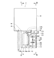
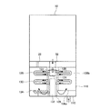
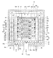
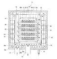
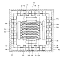
本発明を具現化した発電装置の第1実施例を、図面を参照しながら説明する。図1は、本実施例に係る発電装置の縦断面図であり、図2は図1のII−II線縦断面図であり、図3は図1のIII−III線縦断面図であり、図4は発電ユニットの縦断面図であり、図5は図4のV−V線縦断面図であり、図6は図4のVI−VI線横断面図であり、図7は図5の部分断面拡大図である。
図1〜図3に示すように、本実施例の発電装置は、発電ユニット10と、前処理ユニット110とを備えている。前処理ユニット110は、発電ユニット10の下方に配置されている。なお、発電ユニット10については後で詳述する。
(First embodiment)
A first embodiment of a power generator embodying the present invention will be described with reference to the drawings. 1 is a longitudinal sectional view of a power generator according to the present embodiment, FIG. 2 is a longitudinal sectional view taken along line II-II in FIG. 1, and FIG. 3 is a longitudinal sectional view taken along line III-III in FIG. 4 is a longitudinal sectional view of the power generation unit, FIG. 5 is a longitudinal sectional view taken along line VV in FIG. 4, FIG. 6 is a transverse sectional view taken along line VI-VI in FIG. 4, and FIG. FIG.
As shown in FIGS. 1 to 3, the power generation apparatus of the present embodiment includes a
前処理ユニット110について説明する。図1に示すように、前処理ユニット110は、燃料昇温混合部112と、予備改質器114を備えている。
図1と図3に示すように、燃料昇温混合部112は、燃料ガス導入管120、水導入管122、燃料ガス昇温室124、燃料ガス昇温管126、水蒸発室128、混合ガス昇温管130、混合ガス混合室132、混合ガス供給管134を有している。
燃料ガス昇温室124は、金属製の箱状部材であり、燃料ガス導入管120が接続されて、脱硫された燃料ガス(都市ガスやLPガス等)が発電装置の外部から導入される。燃料ガス昇温室124には燃料ガス昇温管126が接続されている。燃料ガス昇温管126は表面積の大きいフレキシブル管またはベローズ管であり、燃料ガス昇温室124から図3中の左右両方向にそれぞれ水平に伸びており、U字状に屈曲し、他端はそれぞれ水蒸発室128に接続されている。
水蒸発室128は、金属製の箱状部材であり、上部に水導入管122が接続されて、図示しない純水器を通過した脱イオン水が水蒸発室128内部に滴下される。水蒸発室128内部の下部には、蓄熱部材としてアルミナボールが詰められている。水蒸発室128には混合ガス昇温管130が接続されている。混合ガス昇温管130もフレキシブル管またはベローズ管であり、水蒸発室128から図3中の左右両方向にそれぞれ水平に伸びており、U字状に屈曲し、他端はそれぞれ混合ガス混合室132に接続されている。
混合ガス混合室132は、金属製の箱状部材であり、下部に混合ガス供給管134が接続されている。混合ガス供給管134は混合ガス混合室132から図3中の左方向に水平に伸びており、U字状に屈曲し、他端は予備改質器114の下部に接続されている。混合ガス供給管134は螺旋状の内壁を有しており、混合ガス供給管134内のガスは、通過する際に攪拌される。
The
As shown in FIGS. 1 and 3, the fuel temperature raising and mixing
The fuel gas
The
The mixed
予備改質器114は、上下方向に伸びる二重円筒形状の金属製の箱状部材であり、軸の部分には、燃焼ガス導出管58が下方向に貫通している。なお、燃焼ガスについては、後で詳述する。燃焼ガス導出管58の上端は発電ユニット10の底部に接続されており、燃焼ガス導出管58の下端は、予備改質器114の下面から前処理ユニット110内に開口している。予備改質器114内には予備改質触媒が充填されている。予備改質触媒は、炭素数2以上の炭化水素をメタンや水素や一酸化炭素に予備改質する反応を促進するものであり、約400℃の温度下において最も反応を促進する。予備改質器114の上部には予備改質ガス導入管26が接続されている。予備改質ガス導入管26の上端は発電ユニット10の底部に接続されている。
The pre-reformer 114 is a metal box-shaped member having a double cylindrical shape extending in the vertical direction. A combustion
前処理ユニット110内に仕切り板136a,136b,136cが配置されている。仕切り板136aは、予備改質器114の下面を支持するように水平に配置されている。仕切り板136bは、予備改質器114と燃料昇温混合部112との間に配置されて仕切り板136aの端部から上方に伸びている。仕切り板136bの上端と前処理ユニット110内の上面との間に隙間が形成されている。仕切り板136cは、予備改質器114の図1中左端であり仕切り板136aの端部から下方の底面に当接するまで伸びている。
前処理ユニット110の上記の部材は、金属製の箱状のケーシング116内に収容されて、発電ユニット10の下方に配置されている。ケーシング116は図示しない断熱材によって被覆されている。発電ユニット10の下方には他に空気導入管34が配置されており、発電ユニット10の下面に接続されている。空気導入管34は、前処理ユニット210の外側に配置されている。
The above-described members of the
燃焼ガスの流れについて説明する。発電ユニット10から燃焼ガス導出管58を経て前処理ユニット110へ導入される燃焼ガスは、約500℃の高温である。高温の燃焼ガスは、予備改質器114の軸部分を上から下へ向かって流れる。予備改質器114を加熱して約400℃まで温度低下した燃焼ガスは、仕切り板136cと仕切り板136aと前処理ユニット110の底面に沿って図1中右方向へ流れる。予備改質器114の図1中右側には燃料昇温混合部112が配設されており、燃焼ガスは、燃料昇温混合部112を構成する、混合ガス供給管134、混合ガス混合室132、混合ガス昇温管130、水蒸発室128、燃料ガス昇温管126、燃料ガス昇温室124を加熱しながら下から上へ向かって流れ、自らは約250℃まで冷却されて、ケーシング116の図1中右側の側壁に形成された燃焼ガス排気口118から排気される。仕切り板136bがあるため、上昇する燃焼ガスが予備改質器114を再度加熱することはない。
The flow of combustion gas will be described. The combustion gas introduced from the
燃料ガスと水蒸気の流れについて説明する。脱硫された燃料ガスは、燃料ガス導入管120から燃料ガス昇温室124内に導入される。燃焼ガスによって加熱された燃料ガスは、燃料ガス昇温管126内を流れながらさらに燃焼ガスによって加熱されて水蒸発室128内に導入される。水蒸発室128内へは水導入管122を経て脱イオン水が滴下される。なお、水蒸発室128内に滴下される水量は、燃料ガス量と所定の割合で混合されるように制御されている。水蒸発室128内に滴下された水は、燃料ガスの熱と、燃焼ガスの熱と、アルミナボールの蓄熱によって気化して水蒸気となり、同時に燃料ガスと混合されて混合ガスとなる。混合ガスは混合ガス昇温管130内を流れながらさらに燃焼ガスによって加熱されて混合ガス混合室132内に導入される。混合ガスは混合ガス混合室132内で整流され、燃焼ガスによってさらに加熱される。混合ガスは混合ガス供給管134内を通過しながら混合され、さらに燃焼ガスによって加熱される。混合ガス供給管134を経た混合ガスは、図1と図2に示すように、予備改質器114の下部から予備改質器114内に導入される。燃料ガスと水蒸気は上記のように流れ、燃焼ガスによって予加熱されながら混合されて混合ガスとなって予備改質器114内に導入される。
予加熱された混合ガスは、予備改質器114内に導入されて予備改質器114内を下から上へ流れながら、予備改質触媒によって改質されて予備改質ガスとなる。予備改質ガスは、予備改質器114の上部に接続された予備改質ガス導入管26を経て、上方の発電ユニット10内に導入される。
The flow of fuel gas and water vapor will be described. The desulfurized fuel gas is introduced into the fuel
The preheated mixed gas is introduced into the pre-reformer 114 and is reformed by the pre-reforming catalyst while flowing from the bottom to the top in the pre-reformer 114 to become a pre-reformed gas. The pre-reformed gas is introduced into the upper
発電ユニットについて説明する。図4から図6に示すように、発電ユニット10は、内側から外側に向かって燃料電池セル群収容室44、燃焼ガス通過室46、空気通過室48からなる3重構造となっており、中心部の燃料電池セル群収容室44とその外側の燃焼ガス通過室46を仕切る内仕切壁36と、燃焼ガス通過室46とその外側の空気通過室48を仕切る外仕切壁38と、空気通過室48と外部を仕切る外壁40を有している。外壁40は断熱部材42で覆われている。
発電ユニット10の中心部の燃料電池セル群収容室44内には、燃料電池セル12の複数個が配列されて構成されている燃料電池セル群14と、酸素を含む空気を燃料電池セル群14に供給する空気供給部材16と、前処理ユニット110内で生成された予備改質ガス内に含まれるメタンを燃料となる水素や一酸化炭素等に改質する改質器18と、改質された改質ガスを燃料電池セル群14に供給するマニホールド24等が配設されている。
The power generation unit will be described. As shown in FIGS. 4 to 6, the
In the fuel cell
図5に明瞭に示されるように、燃料電池セル12の断面は楕円形状であり、複数の燃料電池セル12(図5では図の明瞭化のために6本となっているが、実際にはもっと多い)が平行に配置されている。燃料電池セル12は、水平方向に長く伸びている。
図7は、図5に示す燃料電池セル群14の断面の拡大図である。図7に示すように、燃料極12aは楕円柱形状に形成され、その周面の半分強が固体電解質層12bで覆われ、固体電解質層12bの更に外側を酸素極12cが覆っている。燃料極12aの周面の酸素極12cと反対側はインターコネクタ12dで覆われている。燃料極12aの内部には長手方向に貫通する5本の燃料ガス通路20が並列に形成されている。
燃料極12aは多孔質であり、ニッケル(Ni)を主成分とするニッケル/YSZサーメット(混合焼結体)からなる。固体電解質層12bは緻密質であり、ジルコニア(ZrO2)にイットリア(Y2O3)を加えた混合物からなる。酸素極12cは多孔質であり、ペロブスカイト型酸化物であるLSM(La1−xSrxMnO3)からなる。インターコネクタ12dは導電性セラミックからなる。
隣合う燃料電池セル12の一方の酸素極12cと他方の燃料電池セル12のインターコネクタ12dとの間に、集電部材22が介装されている。集電部材22は、蛇腹状に折畳まれた導電性金属部材である。一方の燃料電池セル12の酸素極12cは、集電部材22とインターコネクタ12dを介して、他方の燃料電池セル12の燃料極12aに電気的に接続されている。多数本の燃料電池セル12が直列に接続されて燃料電池セル群14が形成されている。蛇腹状の集電部材22は、空気が通過することを禁止しない。
As clearly shown in FIG. 5, the cross section of the
FIG. 7 is an enlarged view of a cross section of the
The
A current collecting
燃料電池セル群14は、燃料電池セル12の燃料ガス通路20が略水平面内を伸びるように配列されており、複数本の燃料電池セル12の燃料ガス通路20が略水平面内を伸びている。燃料ガス通路20が同一水平面内を伸びる燃料電池セル群14が、垂直方向に5段に配列されている。燃料電池セル群14を上段から順に、14a、14b,14c,14d,14eということにする。
The
図4と図6に示すように、燃料電池セル群14aの上流側(図4の右側)は、マニホールド24aを介して、改質器18aに接続されている。改質器18aとマニホールド24aは配管30aによって接続されている。燃料電池セル群14cと14eも同様にして改質器18aに接続されている。燃料電池セル群14bの上流側(図4の左側)は、マニホールド24bを介して、改質器18bに接続されている。改質器18bとマニホールド24bは配管30bによって接続されている。燃料電池セル群14dも同様にして改質器18bに接続されている。
燃料電池セル群14a、14c,14eの燃料ガス通路20には、改質器18aで改質された改質ガスが送り込まれる。燃料電池セル群14a、14c,14eの改質器18aから遠い方(下流側)の端部では燃料ガス通路20が開放されており、発電のために消費されなかった改質ガスが放出される。燃料電池セル群14b,14dの燃料ガス通路20には、改質器18bで改質された改質ガスが送り込まれる。燃料電池セル群14b,14dの改質器18bから遠い方(下流側)の端部では燃料ガス通路20が開放されており、発電のために消費されなかった改質ガスが放出される。燃料電池セル群14a、14c,14eは、マニホールド24a,24c,24eによって片持ち状に支持され、燃料電池セル群14b,14dは、マニホールド24b,24dによって片持ち状に支持されている。
燃料電池セル群14a、14c,14eと、燃料電池セル群14b,14dは、反対方向に伸びている。上下方向に多段に配列されている燃料電池セル群14a、14b,14c,14d、14eは、上下方向において、交互に反対向きに配列されている。
As shown in FIGS. 4 and 6, the upstream side (right side in FIG. 4) of the
The reformed gas reformed by the
The
一対の改質器18a、18bは、基本的に同一構成を備えている。以下で添字を省略して共通に説明する。改質器18は、金属製の薄い箱形状のケーシングと、その内で蛇行する経路(図示省略)が形成されており、この経路内に改質触媒が充填されている。図4に示すように、一対の改質器18a,18bは、燃料電池セル群14群を挟んで、平行に配設されている。一対の改質器18a,18bは、上部の2箇所の角部で2本の渡り配管28a,28bによって接続されている。予備改質ガス導入管26から送られた予備改質ガスは一方の改質器18aに導入され、渡り配管28aを経て、他方の改質器18bにも導入される。改質器18a,18b内に導入された予備改質ガス中のメタンは、改質触媒によって、改質器18内を通過する間に主に水素や一酸化炭素からなる改質ガスに改質される。なお、渡り配管28bは、2つの改質器18a,18bの出口圧力の均衡を調整するために配設されている。
The pair of
図4〜図6に示すように、空気供給部材16は浅い箱形状の部材であり、上面に複数の空気供給口16fが形成されている。空気供給部材16の両側面には略水平に伸びる邪魔板52a,52bが形成されている。邪魔板52aは、上段の燃料電池セル12の上流側に向けて取付けられており、水平に伸びている。邪魔板52bは、上段の燃料電池セル12の下流側に向けて取付けられており、端部が若干上向きに取付けられている。空気供給部材16a,16b,16c,16d,16eは、燃料電池セル群14a,14b,14c,14d,14eのそれぞれの下方に配設されており、5つの空気供給部材16a,16b,16c,16d,16eが上下方向に5段に配設されている。各空気供給部材16の両端部は夫々空気供給管50に連通している。空気供給管50は金属製であり、図4と図5に示すように、上下方向に伸びており、上端は空気通過室48に開口している。空気通過室48の下方は、空気導入管34と連通しており、空気導入管34によって外部から導入された空気は、空気通過室48を通過して一対の空気供給管50,50のいずれかに流入し、上下5段の空気供給部材16a,16b,16c,16d,16eのいずれかの上面から、直近上部の燃料電池セル群14a,14b,14c,14d,14eに空気を供給する。
上下5段の空気供給部材16a,16b,16c,16d,16eは、両端が空気供給管50によって支持されており、強度が高い。
図4〜図6に示すように、燃料電池セル群14の燃料ガス通路20は左右方向に伸びており、空気供給部材16は、上下方向に伸びている。両持ち状の空気供給部材16と、片持ち状の燃料電池セル群14が交差する位置関係におかれている。
As shown in FIGS. 4 to 6, the
The upper and lower five-stage
As shown in FIGS. 4-6, the fuel gas channel |
片持ち状の燃料電池セル群14は、両持ち状の空気供給部材16に対してパッキン62を介して載置されており、片持ち状の燃料電池セル群14は水平に伸びる姿勢で安定的に支持されている。片持ち状の燃料電池セル群14が不用意に傾くことはない。
The cantilevered
空気通過室48と燃焼ガス通過室46を仕切る外仕切壁38の4つの外周面には、図4から図6に示すフィン54が取付けられている。特に図6に示すように、フィン54は横方向に長尺な金属製板部材を略蛇腹形状に折畳んで形成されている。外側は外壁40の内面に接触しており、内側は外仕切壁38の外面に接触している(図4〜図6ではフィン54の形状を明瞭にするため、フィン54と壁面を離して示している)。なお、放熱を防止するために、フィン54と外壁40の内面が、断熱材を介して接触する構成であってもよい。図4と図5に示すように、外仕切壁38の4つの外周面には、複数のフィン54が上下方向に取付けられて外周面を覆っている。図示はしていないが、上下のフィン54は、ピッチを半分ずらして取付けられている。このようにフィン54が取付けられているため、外仕切壁38とフィン54と外壁40によって、外仕切壁38の4つの外周面と外壁40の内面との間の全体に亘って、上下方向に伸びる細い角柱形状の通路が複数本形成される。
図4から図6に示すように、外仕切壁38の4つの内周面にも、フィン54と同様にフィン56が取付けられている。フィン56の形状もフィン54と同様である。このようにフィン56が取付けられているため、外仕切壁38とフィン56と内仕切壁36によって、外仕切壁38の4つの内周面と内仕切壁36の外面との間の全体に亘って、上下方向に伸びる細い角柱形状の通路が複数本形成される。フィン54は空気通過室48のサイズを規定し、フィン56は燃焼ガス通過室46のサイズを規定する。
As shown in FIGS. 4 to 6, the
図4と図5に示すように、外仕切壁38は、側壁の下端から下方に伸びる固定用壁38aによって外壁40の底板に固定されている。燃焼ガス通過室46の底板は空気通過室48の底板から持ち上げられている。両底板の間隙は空気通過室48の一部を構成する。固定用壁38aには複数個の穴38bが形成されており、空気の流通が自在となっている。内仕切壁36も、側壁の下端から下方に伸びる固定用壁36aによって外仕切壁38の底板に固定されている。燃料電池セル群収容室44の底板は燃焼ガス通過室46の底板から持ち上げられている。両底板の間隙は燃焼ガス通過室46の一部を構成する。固定用壁36aにも複数個の穴36bが形成されており、空気の流通が自在となっている。
外壁40の底板と外仕切壁38の底板の間は、空気通過室48の一部であり、そこに空気導入管34が連通している。外仕切壁38の底板と内仕切壁36の底板の間は、燃焼ガス通過室46の一部であり、そこに燃焼ガス導出管58が連通している。
As shown in FIGS. 4 and 5, the
Between the bottom plate of the
空気通過室48は、発電ユニット10の6面(4側面と上面と底面)において、燃焼ガス通過室46を取り囲んでおり、燃焼ガス通過室46は、発電ユニット10の6面(4側面と上面と底面)において、燃料電池セル群収容室44を取り囲んでいる。
空気通過室48は、外部から取り込まれた空気が通過する。燃焼ガス通過室46は、燃料電池セル群収容室44で生成された燃焼ガスが通過する。燃料電池セル群収容室44内には燃料電池セル群14が収容される。
空気は空気通過室48を下方から上方に移動する。燃焼ガスは燃焼ガス通過室46を上方から下方に通過する。通過方向が逆であり、両者の間で活発な熱交換が行われる。
燃料電池セル群収容室44の外形はほぼ立方体である。燃焼ガス通過室46の外形もほぼ立方体である。空気通過室48の外形もほぼ立方体である。発電ユニット10は、最小表面積で最大容積を収容する6面体であり、放熱量が少ない。
後記するように、燃料電池セル群収容室44は最も高温であり、燃焼ガス通過室46は2番目に高温であり、空気通過室48が3番目に高温である。最も高温な燃料電池セル群収容室44を、2番目に高温な燃焼ガス通過室46で取り囲み、その外側を3番目に高温な空気通過室48で取り囲む構造となっている。最も高温に維持する必要がある燃料電池セル群収容室44を最も内側に配置することによって、燃料電池セル群収容室44を最も高温に維持しやすい最適な構造となっている。
The
Air taken in from outside passes through the
The air moves in the
The outer shape of the fuel cell
As will be described later, the fuel cell
発電ユニット10内の動作を説明する。
前処理ユニット110内で生成され、予備改質ガス導入管26から改質器18a,18bに送られた予備改質ガスは、改質器18a,18b内で、水素と一酸化炭素を含む改質ガスに改質され、各マニホールド24に送られる。改質された改質ガスは、各マニホールド24から各燃料電池セル12へ送られ、各燃料電池セル12内の燃料ガス通路20に流入する。
空気導入管34から空気通過室48に送られた空気は、フィン54の間をすり抜けて上部に達し、外壁40の上面に沿って流れ、空気通過室48に開口している空気供給管50内に流入する。空気は、空気供給管50を下方に移動しながら、5つの空気供給部材16に流入し、全ての空気供給口16fから流出する。流出する空気は、上方向、若しくは斜め上方向に上昇し、すぐ上の燃料電池セル群14の下側全体に分散される。
酸素は、イオン化して固体電解質を通過して燃料極に至り、水素または一酸化炭素と反応し、酸素極と燃料極の間に電位差を発生させる。すなわち、発電する。
The operation in the
The pre-reformed gas generated in the
The air sent from the
Oxygen ionizes, passes through the solid electrolyte, reaches the fuel electrode, reacts with hydrogen or carbon monoxide, and generates a potential difference between the oxygen electrode and the fuel electrode. That is, it generates electricity.
発電時、改質ガスは上流から下流へ向かって燃料電池セル群14内を水平に流れる。改質ガスは上流から下流へ流れる間に発電熱によって徐々に加熱されていく。従来のように、燃料電池セル群14を縦に配設して改質ガスを下方から上方へ流し、空気も下方から上方へ流して発電を行うと、改質ガスも空気も下方から上方へ流れる間に発電熱で加熱され、燃料電池セル群14の上部と下部の温度差が例えば150℃近く生じてしまう。発電効率を考慮すると、下方の低温側の作動温度が、最適作動温度である例えば800℃になるように調整しなければならない。すると、上方の高温側の動作温度が950℃にまで上昇してしまう。この高温に対する熱耐久性を確保するためには、燃料電池セル12の近傍に配設される部材の熱耐久性を確保しなければならず、コストアップは避けられない。熱耐久性を重視すれば、上方の高温側の作動温度が、最適作動温度である800℃になるように調整しなければならない。すると、下方の低温側の動作温度が650℃にまで低下してしまい、発電効率の低下は否めない。
本実施例の燃料電池では、燃料電池セルが水平方向に伸びているのに対し、空気が上方に移動する関係が得られ、燃料電池セルの温度勾配に交差する有酸素ガスの流れが生み出される。燃料電池セルを冷却する空気に燃料電池を冷却した熱が累積していくことが抑制され、燃料電池セルの上流端と下流端の温度差が小さくなる。さらに、燃料電池セル群は1段毎に燃料ガス通路の向きが交互になるように配列されている。即ち、燃料電池セルの低温な上流側と高温な下流側が垂直方向に交互に配置されている。従って、上下方向の温度差が相殺され、燃料電池セルの上流側と下流側の温度差がさらに小さくなり、燃料電池セル群収容室44内の温度差が減少する。
During power generation, the reformed gas flows horizontally in the
In the fuel cell of this embodiment, the fuel cell extends in the horizontal direction, whereas the relationship in which the air moves upward is obtained, and a flow of aerobic gas that intersects the temperature gradient of the fuel cell is generated. . Accumulation of the heat that has cooled the fuel cell in the air that cools the fuel cell is suppressed, and the temperature difference between the upstream end and the downstream end of the fuel cell is reduced. Further, the fuel cell groups are arranged so that the directions of the fuel gas passages are alternated for each stage. That is, the low temperature upstream side and the high temperature downstream side of the fuel cell are alternately arranged in the vertical direction. Therefore, the temperature difference in the vertical direction is offset, the temperature difference between the upstream side and the downstream side of the fuel cell is further reduced, and the temperature difference in the fuel cell
本実施例では、燃料電池セル群14の下方に配置されている空気供給部材16の広い範囲に空気供給口が分散配置されており、燃料電池セル群14の下側全体に空気が分散して供給される。これもまた、燃料電池セル群14の上流から下流に至るまで一様温度に冷却するのに有利である。
本実施例では、加熱されやすい燃料電池セル群14の下流側に多量の空気が供給され、加熱されにくい燃料電池セル群14の上流側に少量の空気が供給されるように、空気供給口16fの密度と開口面積が調整されている。これもまた、燃料電池セル群14の温度分布を一様化するのに寄与している。
In the present embodiment, the air supply ports are distributed over a wide range of the
In this embodiment, a large amount of air is supplied to the downstream side of the
本実施例では、燃料電池セル群14の直下に熱伝導性の高い金属で形成された空気供給部材16が配置されている。空気供給部材16は熱伝導性が高く、加熱されやすい燃料電池セル群14の下流側から加熱されにくい燃料電池セル群14の上流側に伝熱する。燃料電池セル群14の近傍に伝熱部材を配置することもまた、燃料電池セル群14の温度分布を一様化するのに寄与している。
熱伝導性の空気供給部材16と燃料電池セル群14の間には、パッキン62が介在しており、直接には接触していない。それでも、熱伝導性の空気供給部材16は、燃料電池セル群14の上流側と下流側の温度差を小さく抑える。加熱されやすい燃料電池セル群14の下流側では、輻射が活発に起こって熱伝導性の空気供給部材16に熱を伝える。燃料電池セル群14の下流側の温度は低下する。輻射によって加熱された熱伝導性の空気供給部材16は、熱伝導によって低温部を加熱する。加熱された空気供給部材16は、相対的に低温な燃料電池セル群14の上流側に向けて輻射し、燃料電池セル群14の上流部を加熱する。熱伝導性の空気供給部材16が燃料電池セル群14に直接には接触していなくても、近接して位置しているために、熱伝導性の空気供給部材16は、燃料電池セル群14の高温部から低温部に伝えられる熱エネルギーの移動を促進する。
In the present embodiment, an
A packing 62 is interposed between the thermally conductive
本実施例では、燃料電池セル群14が垂直方向に5段に配列されている。上下方向に隣接する燃料電池セル群14の間は、空気供給部材16と邪魔板52a,52bによって仕切られており、下段の燃料電池セル群14を冷却することによって自らは加熱された空気で上段の燃料電池セル群14を冷却するものではない。各段の燃料電池セル群14毎に、冷却兼発電用の空気が送られてくる。熱環境が等しい燃料電池セル群14が上下方向に5段に配列されるだけであり、燃料電池セル群収容室44内の上下方向の温度差も抑制される。
In this embodiment, the
本実施例では、空気供給部材16がガス流遮断板を兼用している。余分な部材を利用しないで、空気供給部材16がガス流遮断板を形成することができる。空気供給部材16がガス流遮断板を兼用するほど広く広がっているために、空気供給部材16から供給される空気が燃料電池セル群14の全体を加熱前の空気で一様によく冷却する。
In this embodiment, the
燃料電池セル12に供給される改質ガスの例えば80%が発電に利用される場合、発電に利用されなかった20%の改質ガス(オフガス)は、燃料ガス通路20を通過して先端から流出する。また、燃料電池セル12に供給される空気の例えば20%が発電に利用される場合、発電に利用されなかった80%の空気は、燃料電池セル群14の集電部材22の隙間をすり抜ける。この空気は邪魔板52bに沿って燃料電池セル12の下流側へ誘導される。
各燃料電池セル12の先端近傍には夫々スパーク電極60が配設されている。スパーク電極60が火花放電することによって、燃料電池セル12の先端から流出する改質ガスのオフガスと、燃料電池セル12の下流側へ誘導される空気のオフガスが燃焼する。改質器18は燃料電池セル12の先端に近接していることから、改質ガスのオフガスと空気のオフガスとの燃焼によって発生する燃焼熱を改質反応の吸熱反応に効率よく利用することができる。
燃焼ガスは極めて高温であり、そのままでは熱交換器に投入しがたい。それほどの高温に耐えられる熱交換器は材質が限られ、高価である。本実施例では、燃焼熱でまず改質器18を加熱する。改質反応は吸熱反応であり、燃焼ガスの熱は吸熱に利用される。燃焼熱でまず改質器18を加熱するために、燃焼ガスの温度は低下する。このために、燃焼ガス通過室46を流れる燃焼ガスの温度は適度に冷却されており、仕切り壁36,38に特別の材料を使わなくてもすむ。
本実施例では、改質器18と各燃料電池セル12との間にマニホールド24が配置されている。燃焼ガスは改質器18に向かって流れ、マニホールド24によって、燃焼ガスが燃料電池セル群14間に進入することが阻まれ、改質器18に沿って流れる。この作用によって、燃料電池セル12が燃焼ガスによって過熱されることを防止し、燃焼ガスによって改質器18を効果的に加熱して、改質反応を促進することができる。
When, for example, 80% of the reformed gas supplied to the
A
The combustion gas is extremely hot and is difficult to put into the heat exchanger as it is. Heat exchangers that can withstand such high temperatures are limited in material and expensive. In this embodiment, the
In the present embodiment, a manifold 24 is disposed between the
本実施例では、燃料と空気のオフガスが燃焼する位置が、上下方向において、交互に反対側に位置する関係に設定されている。このために、燃料電池セル群収容室44内の温度分布は、水平方向にも上下方向にも均質化されている。燃料電池セル群収容室44内の最大温度差でも50℃程度であり、燃料電池セル群収容室44内の温度は800〜850℃の範囲に抑えられる。
In the present embodiment, the position where the off-gas of fuel and air burns is set so as to be alternately positioned on the opposite side in the vertical direction. For this reason, the temperature distribution in the fuel cell
また、最も高温な燃料電池セル群収容室44を2番目に高温な燃焼ガス通過室46で取り囲み、その外側を3番目に高温な空気通過室48で取り囲む構造となっているために、燃料電池セル群収容室44を高温に維持しやすい。そのために、発電に伴って発生する熱と、改質ガスと空気のオフガスの燃焼熱だけで、燃料電池セル群収容室44内の温度を発電適温である800〜850℃に維持することができる。
Further, the fuel cell
燃料電池セル12の電気化学反応が効率よく進行する環境温度は約800℃の高温である。この環境温度が低下すれば、発電効率は低下する。従って、燃料電池セル12に供給する空気の温度を予加熱しておく必要がある。
上昇した燃焼ガスは、燃料電池セル群収容室44の上面に沿って燃焼ガス通過室46に流入する。燃焼ガス通過室46内に流入した燃焼ガスは、上下方向に伸びる複数の細い角柱形状の通路を下方向に通過して燃焼ガス通過室46の下部に流入し、燃焼ガス導出管58から前処理ユニット110内に導出される。
このとき、空気導入管34から導入された予加熱された空気(約200℃)は空気通過室48内に流入し、上下方向に伸びる複数の細い角柱形状の通路を上方向に通過している。従って、燃焼ガス通過室46を通過する燃焼ガスと、空気通過室48を通過する空気との間で熱交換が行われる。外仕切板38の両面に取付けられたフィン54,56によって、熱交換率は更に高められる。この熱交換によって、空気を約650℃まで予加熱しておくことができる。約500℃まで温度低下した燃焼ガスは、前処理ユニット110内に配設された予備改質器114の加熱や、燃料ガスと水蒸気を昇温させて混合する燃料昇温混合部112の加熱に利用する。
The environmental temperature at which the electrochemical reaction of the
The rising combustion gas flows into the combustion
At this time, preheated air (about 200 ° C.) introduced from the
本実施例では、発電ユニット10から、燃焼ガスが燃焼ガス導出管58を経て前処理ユニット110内へ導入される。燃焼ガスは、まず予備改質器114を加熱して予備改質を促進するのに利用される。次に燃焼ガスは、予備改質器110に導入する燃料ガスと水蒸気の混合ガスを予加熱するのに利用される。燃焼ガスは、前処理ユニット110内の、混合ガス供給管134、混合ガス混合室132、混合ガス昇温管130、水蒸発室128、燃料ガス昇温管126、燃料ガス昇温室124を順に加熱する。燃料ガスは、この逆の順に流れ、水を気化させ、その水蒸気と混合されながら、燃焼ガスによって加熱される。燃料ガスは、外部から導入されて、流れていくにつれて、徐々に高温に加熱されていくため、混合ガス中の水分が結露するおそれはない。この構成によって、加熱のための資源を消費することなく、予備改質器110と、予備改質器110に導入する燃料ガスと水蒸気の混合ガスをいずれも良好に予加熱することができる。熱効率がさらに向上する。
In the present embodiment, the combustion gas is introduced from the
燃料ガスと水蒸気の混合が不均一であると、混合ガス中の水蒸気濃度が不足する部分が生じる。混合ガス中の水蒸気濃度が不足していると、炭素が析出して配管を閉塞してしまう不具合が生じる。
本実施例では、前処理ユニット110内の燃料昇温混合部112において、燃料ガスと水蒸気の混合比を制御することができ、混合ガス供給管134の内部構造によって、燃料ガスと水蒸気を良好に攪拌することができる。これによれば、燃料ガスと水蒸気を所定の割合で均一に混合させることができ、炭素が析出する不具合を解消することができる。
燃焼ガスによって加熱された燃料ガスを水蒸発室128に導入して水を滴下すると、燃料ガスの熱によって水は気化して水蒸気となる。それと同時に燃料ガスと水蒸気は混合され、燃料ガスの流量と、水の注入量を調整することによって、燃料ガスと水蒸気の混合比を均一化することができる。
If the mixing of the fuel gas and water vapor is not uniform, there will be a portion where the water vapor concentration in the mixed gas is insufficient. If the water vapor concentration in the mixed gas is insufficient, there is a problem that carbon is deposited and the piping is blocked.
In this embodiment, the fuel gas / water vapor mixing ratio can be controlled in the fuel temperature raising and mixing
When the fuel gas heated by the combustion gas is introduced into the
以上の実施例では、筒状の燃料極を燃料ガス通路が貫通している燃料電池セルの例を説明したが、燃料極と燃料ガス通路の関係はそれに限らない。例えば、ポーラスの物質の中に燃料ガス通路を設け、その表面に、内側から、燃料極、固体電解質、酸素極の順に積層された積層構造を付着したような燃料電池セルであってもよい。要は、燃料極と固体電解質と酸素極の積層体の燃料極側に改質ガスが供給され、酸素極側に有酸素ガスが供給されるものであり、かつ、燃料電池セルの外側に供給される有酸素ガスが、前記積層体を通して燃料電池セル側に用意されている燃料ガス通路に侵入するものであれば足りる。 In the above embodiment, an example of the fuel cell in which the fuel gas passage penetrates the cylindrical fuel electrode has been described. However, the relationship between the fuel electrode and the fuel gas passage is not limited thereto. For example, a fuel cell may be provided in which a fuel gas passage is provided in a porous material and a laminated structure in which a fuel electrode, a solid electrolyte, and an oxygen electrode are laminated in this order from the inside. In short, the reformed gas is supplied to the fuel electrode side of the laminate of the fuel electrode, the solid electrolyte, and the oxygen electrode, the oxygenated gas is supplied to the oxygen electrode side, and supplied to the outside of the fuel cell. It is sufficient that the aerobic gas to be introduced enters the fuel gas passage prepared on the fuel cell side through the laminate.
(第2実施例)
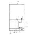
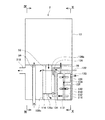
本発明を具現化した発電装置の第2実施例を、図面を参照しながら説明する。図8は、本実施例に係る発電装置の縦断面図であり、図9は図8のIX−IX線縦断面図であり、図10は図8のX−X線縦断面図である。本実施例は、第1実施例の発電装置と、前処理ユニットの構成が異なっている。従って、主に、前処理ユニットについて説明し、第1実施例と同様である部分の説明や図示を省略する。また、共通する部材については同一符号とする。
本実施例の発電装置では、図8と図9に示すように、前処理ユニット210内に、発電ユニット10内に空気を導入する空気導入管34が配置されている。
図8から図10に示すように、前処理ユニット210のケーシング216の四方の夫々の側面は、上方の発電ユニット10の四方の夫々の側面と連続するように形成されており、発電ユニット10と前処理ユニット210が一体化した外観となっている。
(Second embodiment)
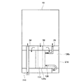
A power generator according to a second embodiment of the present invention will be described with reference to the drawings. 8 is a longitudinal sectional view of the power generator according to the present embodiment, FIG. 9 is a longitudinal sectional view taken along line IX-IX in FIG. 8, and FIG. 10 is a longitudinal sectional view taken along line XX in FIG. This embodiment is different from the power generation apparatus of the first embodiment in the configuration of the pretreatment unit. Accordingly, the preprocessing unit will be mainly described, and the description and illustration of the same parts as those in the first embodiment will be omitted. Moreover, the same code | symbol is used about a common member.
In the power generation apparatus of this embodiment, as shown in FIGS. 8 and 9, an
As shown in FIGS. 8 to 10, the four side surfaces of the
燃焼ガスの流れについて説明する。発電ユニット10から燃焼ガス導出管58を経て前処理ユニット210へ導入される燃焼ガスは、約500℃の高温である。高温の燃焼ガスは、予備改質器114の軸部分を上から下へ向かって流れる。予備改質器114を通過して約400℃となった燃焼ガスは、仕切り板136cと仕切り板136aと前処理ユニット110の底面に沿って図8中右方向へ流れる。予備改質器114の図8中右側には燃料昇温混合部112が配設されており、燃焼ガスは、燃料昇温混合部112を構成する、混合ガス供給管134、混合ガス混合室132、混合ガス昇温管130、水蒸発室128、燃料ガス昇温管126、燃料ガス昇温室124を加熱しながら下から上へ向かって流れる。前処理ユニット210内の上面に達した燃焼ガスは、約250℃となっている。燃焼ガスは、仕切り板136bの上端と前処理ユニット210内の上面の間を通り抜けて、予備改質器114の図8中左側に予備改質器114と仕切り板136cとによって形成される空間に進入する。この空間には空気導入管34が配置されており、燃焼ガスは空気導入管34を加熱する。燃焼ガスは、ケーシング216の図8中左側の側壁の上部に形成された燃焼ガス排気口218から排気される。
The flow of combustion gas will be described. The combustion gas introduced from the
本実施例の発電装置では、前処理ユニット210内に、発電ユニット10内に空気を導入する空気導入管34が配置されている。燃焼ガスは、予備改質器114と燃料昇温混合部112を加熱した後、空気導入管34を加熱する。これにより、空気導入管34内を流れる空気を効率よく予加熱することができ、発電効率をさらに向上することができる。
In the power generation apparatus according to this embodiment, an
以上、本発明の具体例を詳細に説明したが、これらは例示にすぎず、特許請求の範囲を限定するものではない。特許請求の範囲に記載の技術には、以上に例示した具体例を様々に変形、変更したものが含まれる。
また、本明細書または図面に説明した技術要素は、単独であるいは各種の組み合わせによって技術的有用性を発揮するものであり、出願時請求項記載の組み合わせに限定されるものではない。また、本明細書または図面に例示した技術は複数目的を同時に達成するものであり、そのうちの一つの目的を達成すること自体で技術的有用性を持つものである。
Specific examples of the present invention have been described in detail above, but these are merely examples and do not limit the scope of the claims. The technology described in the claims includes various modifications and changes of the specific examples illustrated above.
In addition, the technical elements described in the present specification or the drawings exhibit technical usefulness alone or in various combinations, and are not limited to the combinations described in the claims at the time of filing. In addition, the technology illustrated in the present specification or the drawings achieves a plurality of objects at the same time, and has technical utility by achieving one of the objects.
10:発電ユニット
12:燃料電池セル、12a:燃料極、12b:固体電解質層、12c:酸素極、12d:インターコネクタ
14:燃料電池セル群
16:空気供給部材、16f:空気供給口
18:改質器、18a、18b
20:燃料ガス通路
22:集電部材
24:マニホールド
26:予備改質ガス導入管
28:渡り配管、28a,28b
30:配管
32:配管
34:空気導入管
36:内仕切壁
38:外仕切壁
40:外壁
42:断熱部材
44:燃料電池セル群収容室
46:燃焼ガス通過室
48:空気通過室
50:空気供給管
52:邪魔板
54:フィン
56:フィン
58:燃焼ガス導出管
60:スパーク電極
62:パッキン
110:前処理ユニット
112:燃料昇温混合部
114:予備改質器
116:ケーシング
118:燃焼ガス排気口
120:燃料ガス導入管
122:水導入管
124:燃料ガス昇温室
126:燃料ガス昇温管
128:水蒸発室
130:混合ガス昇温管
132:混合ガス混合室
134:混合ガス供給管
136:仕切り板
210:前処理ユニット
216:ケーシング
218:燃焼ガス排気口
10: power generation unit 12: fuel cell, 12a: fuel electrode, 12b: solid electrolyte layer, 12c: oxygen electrode, 12d: interconnector 14: fuel cell group 16: air supply member, 16f: air supply port 18: modified Pouch, 18a, 18b
20: Fuel gas passage 22: Current collecting member 24: Manifold 26: Preliminary reformed gas introduction pipe 28: Transition pipe, 28a, 28b
30: piping 32: piping 34: air introduction pipe 36: inner partition wall 38: outer partition wall 40: outer wall 42: heat insulating member 44: fuel cell group accommodation chamber 46: combustion gas passage chamber 48: air passage chamber 50: air Supply pipe 52: Baffle plate 54: Fin 56: Fin 58: Combustion gas outlet pipe 60: Spark electrode 62: Packing 110: Pretreatment unit 112: Fuel temperature raising and mixing unit 114: Pre-reformer 116: Casing 118: Combustion gas Exhaust port 120: Fuel gas introduction pipe 122: Water introduction pipe 124: Fuel gas temperature raising chamber 126: Fuel gas temperature raising pipe 128: Water evaporation room 130: Mixed gas temperature raising pipe 132: Mixed gas mixing room 134: Mixed gas supply pipe 136: Partition plate 210: Pretreatment unit 216: Casing 218: Combustion gas exhaust port
Claims (6)
昇温蒸発混合器で得られた混合ガスを予備改質ガスに改質する予備改質器と、
予備改質ガスを改質ガスに改質する改質器と、
改質ガスを受入れて発電する固体酸化物型の燃料電池セルと、
燃料電池セルで利用されなかった改質ガスを燃焼する燃焼部と、
燃焼部で得られた燃焼ガスを昇温蒸発混合器と予備改質器の周囲とを通過させる燃焼ガス導出路と、
を有する発電装置。 A temperature-evaporating mixer that raises the temperature of the fuel gas and mixes it with water vapor;
A pre-reformer for reforming the mixed gas obtained in the temperature-evaporating mixer into a pre-reformed gas;
A reformer for reforming the pre-reformed gas into a reformed gas;
A solid oxide fuel cell that receives the reformed gas and generates power;
A combustion section for burning the reformed gas that has not been used in the fuel cell;
A combustion gas outlet passage through which the combustion gas obtained in the combustion section passes through the temperature-evaporating mixer and the periphery of the pre-reformer;
A power generator.
Priority Applications (1)
| Application Number | Priority Date | Filing Date | Title |
|---|---|---|---|
| JP2004104688A JP4751580B2 (en) | 2004-03-31 | 2004-03-31 | Power generator |
Applications Claiming Priority (1)
| Application Number | Priority Date | Filing Date | Title |
|---|---|---|---|
| JP2004104688A JP4751580B2 (en) | 2004-03-31 | 2004-03-31 | Power generator |
Publications (2)
| Publication Number | Publication Date |
|---|---|
| JP2005293934A true JP2005293934A (en) | 2005-10-20 |
| JP4751580B2 JP4751580B2 (en) | 2011-08-17 |
Family
ID=35326654
Family Applications (1)
| Application Number | Title | Priority Date | Filing Date |
|---|---|---|---|
| JP2004104688A Expired - Fee Related JP4751580B2 (en) | 2004-03-31 | 2004-03-31 | Power generator |
Country Status (1)
| Country | Link |
|---|---|
| JP (1) | JP4751580B2 (en) |
Cited By (16)
| Publication number | Priority date | Publication date | Assignee | Title |
|---|---|---|---|---|
| JP2009032648A (en) * | 2007-06-27 | 2009-02-12 | Kyocera Corp | Fuel cell device |
| JP2009032652A (en) * | 2007-06-27 | 2009-02-12 | Kyocera Corp | Heat exchanger and fuel cell apparatus having the same |
| JP2009170402A (en) * | 2007-12-18 | 2009-07-30 | Ricoh Co Ltd | Fuel cell and fuel cell system |
| JP2010080258A (en) * | 2008-09-26 | 2010-04-08 | Kyocera Corp | Fuel cell device |
| JP2012515415A (en) * | 2009-01-12 | 2012-07-05 | ドゥサン ヘヴィー インダストリーズ アンド コンストラクション カンパニー リミテッド | Fuel electrode steam generator combined with fuel electrode gas heating |
| JP2013243150A (en) * | 2013-07-19 | 2013-12-05 | Tokyo Gas Co Ltd | Off-gas combustion device and off-gas combustion method of solid oxide fuel cell |
| JP2016149250A (en) * | 2015-02-12 | 2016-08-18 | 株式会社デンソー | Fuel cell device |
| JP2017183128A (en) * | 2016-03-31 | 2017-10-05 | Toto株式会社 | Solid oxide fuel cell device |
| KR20180073714A (en) * | 2015-11-17 | 2018-07-02 | 퓨얼 셀 에너지, 인크 | Hydrogen and carbon monoxide generation using an rep with partial oxidation |
| US10608272B2 (en) | 2015-11-16 | 2020-03-31 | Fuelcell Energy, Inc. | System for capturing CO2 from a fuel cell |
| US10680265B2 (en) | 2015-11-16 | 2020-06-09 | Fuelcell Energy, Inc. | Energy storage using an REP with an engine |
| US10892507B2 (en) | 2014-01-31 | 2021-01-12 | Fuelcell Energy, Inc. | Reformer-electrolyzer-purifier (REP) assembly for hydrogen production, systems incorporating same and method of producing hydrogen |
| US10897055B2 (en) | 2017-11-16 | 2021-01-19 | Fuelcell Energy, Inc. | Load following power generation and power storage using REP and PEM technology |
| US11043684B2 (en) | 2015-11-17 | 2021-06-22 | Fuelcell Energy, Inc. | Fuel cell system having enhanced CO2 capture |
| US11339333B2 (en) | 2016-04-21 | 2022-05-24 | Fuelcell Energy, Inc. | Fluidized catalytic cracking unit system with integrated reformer-electrolyzer-purifier |
| US11495806B2 (en) | 2019-02-04 | 2022-11-08 | Fuelcell Energy, Inc. | Ultra high efficiency fuel cell power generation system |
Citations (4)
| Publication number | Priority date | Publication date | Assignee | Title |
|---|---|---|---|---|
| JP2003516294A (en) * | 1999-12-09 | 2003-05-13 | ザ リージェンツ オブ ザ ユニバーシティ オブ カリフォルニア | Hydrogen production from carbon materials |
| JP2003183008A (en) * | 2002-12-17 | 2003-07-03 | Matsushita Electric Ind Co Ltd | Hydrogen generator |
| JP2003229164A (en) * | 2002-02-05 | 2003-08-15 | Tokyo Gas Co Ltd | Solid oxide fuel cell system |
| WO2003092102A1 (en) * | 2002-04-23 | 2003-11-06 | Ceramic Fuel Cells Limited | Method of operating a fuel cell |
-
2004
- 2004-03-31 JP JP2004104688A patent/JP4751580B2/en not_active Expired - Fee Related
Patent Citations (4)
| Publication number | Priority date | Publication date | Assignee | Title |
|---|---|---|---|---|
| JP2003516294A (en) * | 1999-12-09 | 2003-05-13 | ザ リージェンツ オブ ザ ユニバーシティ オブ カリフォルニア | Hydrogen production from carbon materials |
| JP2003229164A (en) * | 2002-02-05 | 2003-08-15 | Tokyo Gas Co Ltd | Solid oxide fuel cell system |
| WO2003092102A1 (en) * | 2002-04-23 | 2003-11-06 | Ceramic Fuel Cells Limited | Method of operating a fuel cell |
| JP2003183008A (en) * | 2002-12-17 | 2003-07-03 | Matsushita Electric Ind Co Ltd | Hydrogen generator |
Cited By (21)
| Publication number | Priority date | Publication date | Assignee | Title |
|---|---|---|---|---|
| JP2009032648A (en) * | 2007-06-27 | 2009-02-12 | Kyocera Corp | Fuel cell device |
| JP2009032652A (en) * | 2007-06-27 | 2009-02-12 | Kyocera Corp | Heat exchanger and fuel cell apparatus having the same |
| JP2009170402A (en) * | 2007-12-18 | 2009-07-30 | Ricoh Co Ltd | Fuel cell and fuel cell system |
| JP2010080258A (en) * | 2008-09-26 | 2010-04-08 | Kyocera Corp | Fuel cell device |
| JP2012515415A (en) * | 2009-01-12 | 2012-07-05 | ドゥサン ヘヴィー インダストリーズ アンド コンストラクション カンパニー リミテッド | Fuel electrode steam generator combined with fuel electrode gas heating |
| JP2013243150A (en) * | 2013-07-19 | 2013-12-05 | Tokyo Gas Co Ltd | Off-gas combustion device and off-gas combustion method of solid oxide fuel cell |
| US10892507B2 (en) | 2014-01-31 | 2021-01-12 | Fuelcell Energy, Inc. | Reformer-electrolyzer-purifier (REP) assembly for hydrogen production, systems incorporating same and method of producing hydrogen |
| US12525630B2 (en) | 2014-01-31 | 2026-01-13 | Fuelcell Energy, Inc. | Reformer-electrolyzer-purifier (REP) assembly for hydrogen production, systems incorporating same and method of producing hydrogen |
| JP2016149250A (en) * | 2015-02-12 | 2016-08-18 | 株式会社デンソー | Fuel cell device |
| US10608272B2 (en) | 2015-11-16 | 2020-03-31 | Fuelcell Energy, Inc. | System for capturing CO2 from a fuel cell |
| US10680265B2 (en) | 2015-11-16 | 2020-06-09 | Fuelcell Energy, Inc. | Energy storage using an REP with an engine |
| KR101992788B1 (en) * | 2015-11-17 | 2019-06-25 | 퓨얼 셀 에너지, 인크 | Hydrogen and carbon monoxide generation using an rep with partial oxidation |
| US10465305B2 (en) | 2015-11-17 | 2019-11-05 | Fuelcell Energy, Inc. | Hydrogen and carbon monoxide generation using an REP with partial oxidation |
| CN108431047B (en) * | 2015-11-17 | 2020-12-11 | 燃料电池能有限公司 | Hydrogen and carbon monoxide produced by partial oxidation using REP |
| CN108431047A (en) * | 2015-11-17 | 2018-08-21 | 燃料电池能有限公司 | Using REP to generate hydrogen and carbon monoxide using partial oxidation |
| US11043684B2 (en) | 2015-11-17 | 2021-06-22 | Fuelcell Energy, Inc. | Fuel cell system having enhanced CO2 capture |
| KR20180073714A (en) * | 2015-11-17 | 2018-07-02 | 퓨얼 셀 에너지, 인크 | Hydrogen and carbon monoxide generation using an rep with partial oxidation |
| JP2017183128A (en) * | 2016-03-31 | 2017-10-05 | Toto株式会社 | Solid oxide fuel cell device |
| US11339333B2 (en) | 2016-04-21 | 2022-05-24 | Fuelcell Energy, Inc. | Fluidized catalytic cracking unit system with integrated reformer-electrolyzer-purifier |
| US10897055B2 (en) | 2017-11-16 | 2021-01-19 | Fuelcell Energy, Inc. | Load following power generation and power storage using REP and PEM technology |
| US11495806B2 (en) | 2019-02-04 | 2022-11-08 | Fuelcell Energy, Inc. | Ultra high efficiency fuel cell power generation system |
Also Published As
| Publication number | Publication date |
|---|---|
| JP4751580B2 (en) | 2011-08-17 |
Similar Documents
| Publication | Publication Date | Title |
|---|---|---|
| JP4751580B2 (en) | Power generator | |
| JP5512156B2 (en) | Fuel cell | |
| JP5427568B2 (en) | Power generator | |
| JP4778198B2 (en) | Power generator | |
| JP5481181B2 (en) | Power generator | |
| JP4751578B2 (en) | Power generator | |
| JP4704693B2 (en) | Power generator | |
| JP2009110970A (en) | Fuel cell | |
| JP4704696B2 (en) | Power generator | |
| JP4733354B2 (en) | Power generator | |
| JP4942292B2 (en) | Power generator | |
| JP2018092917A (en) | High temperature operation fuel cell system | |
| JP4942287B2 (en) | Power generator | |
| JP4768966B2 (en) | Power generator | |
| JP5009496B2 (en) | Power generator | |
| JP4986403B2 (en) | Power generator | |
| JP4751577B2 (en) | Power generation system | |
| JP2020047399A (en) | Fuel cell device | |
| JP5096436B2 (en) | Power generator | |
| JP4688470B2 (en) | Power generator | |
| JP4965098B2 (en) | Power generator | |
| JP6189605B2 (en) | Fuel cell device | |
| JP2010195625A (en) | Reformer, cell stack device, fuel cell module, and fuel cell apparatus | |
| JP4837260B2 (en) | Power generator | |
| JP6315954B2 (en) | Solid oxide fuel cell |
Legal Events
| Date | Code | Title | Description |
|---|---|---|---|
| A621 | Written request for application examination |
Free format text: JAPANESE INTERMEDIATE CODE: A621 Effective date: 20061214 |
|
| A977 | Report on retrieval |
Free format text: JAPANESE INTERMEDIATE CODE: A971007 Effective date: 20100610 |
|
| A131 | Notification of reasons for refusal |
Free format text: JAPANESE INTERMEDIATE CODE: A131 Effective date: 20100727 |
|
| A521 | Request for written amendment filed |
Free format text: JAPANESE INTERMEDIATE CODE: A523 Effective date: 20100927 |
|
| TRDD | Decision of grant or rejection written | ||
| A01 | Written decision to grant a patent or to grant a registration (utility model) |
Free format text: JAPANESE INTERMEDIATE CODE: A01 Effective date: 20110426 |
|
| A61 | First payment of annual fees (during grant procedure) |
Free format text: JAPANESE INTERMEDIATE CODE: A61 Effective date: 20110523 |
|
| R150 | Certificate of patent or registration of utility model |
Ref document number: 4751580 Country of ref document: JP Free format text: JAPANESE INTERMEDIATE CODE: R150 Free format text: JAPANESE INTERMEDIATE CODE: R150 |
|
| FPAY | Renewal fee payment (event date is renewal date of database) |
Free format text: PAYMENT UNTIL: 20140527 Year of fee payment: 3 |
|
| R250 | Receipt of annual fees |
Free format text: JAPANESE INTERMEDIATE CODE: R250 |
|
| R250 | Receipt of annual fees |
Free format text: JAPANESE INTERMEDIATE CODE: R250 |
|
| R250 | Receipt of annual fees |
Free format text: JAPANESE INTERMEDIATE CODE: R250 |
|
| R250 | Receipt of annual fees |
Free format text: JAPANESE INTERMEDIATE CODE: R250 |
|
| R250 | Receipt of annual fees |
Free format text: JAPANESE INTERMEDIATE CODE: R250 |
|
| R250 | Receipt of annual fees |
Free format text: JAPANESE INTERMEDIATE CODE: R250 |
|
| S111 | Request for change of ownership or part of ownership |
Free format text: JAPANESE INTERMEDIATE CODE: R313117 |
|
| R350 | Written notification of registration of transfer |
Free format text: JAPANESE INTERMEDIATE CODE: R350 |
|
| S111 | Request for change of ownership or part of ownership |
Free format text: JAPANESE INTERMEDIATE CODE: R313117 |
|
| R350 | Written notification of registration of transfer |
Free format text: JAPANESE INTERMEDIATE CODE: R350 |
|
| R250 | Receipt of annual fees |
Free format text: JAPANESE INTERMEDIATE CODE: R250 |
|
| R250 | Receipt of annual fees |
Free format text: JAPANESE INTERMEDIATE CODE: R250 |
|
| LAPS | Cancellation because of no payment of annual fees |