JP2005293919A - Battery, and manufacturing method of clad plate used for the battery, and manufacturing method of lead plate of battery pack parts and battery pack parts and lead plate - Google Patents
Battery, and manufacturing method of clad plate used for the battery, and manufacturing method of lead plate of battery pack parts and battery pack parts and lead plate Download PDFInfo
- Publication number
- JP2005293919A JP2005293919A JP2004104392A JP2004104392A JP2005293919A JP 2005293919 A JP2005293919 A JP 2005293919A JP 2004104392 A JP2004104392 A JP 2004104392A JP 2004104392 A JP2004104392 A JP 2004104392A JP 2005293919 A JP2005293919 A JP 2005293919A
- Authority
- JP
- Japan
- Prior art keywords
- battery
- plate
- battery pack
- lead plate
- attached
- Prior art date
- Legal status (The legal status is an assumption and is not a legal conclusion. Google has not performed a legal analysis and makes no representation as to the accuracy of the status listed.)
- Pending
Links
- 238000004519 manufacturing process Methods 0.000 title claims description 27
- 229910052751 metal Inorganic materials 0.000 claims abstract description 19
- 239000002184 metal Substances 0.000 claims abstract description 19
- 239000000463 material Substances 0.000 claims description 34
- 238000005520 cutting process Methods 0.000 claims description 20
- 238000000034 method Methods 0.000 claims description 17
- 238000000605 extraction Methods 0.000 claims description 13
- 238000010248 power generation Methods 0.000 claims description 9
- 238000005253 cladding Methods 0.000 claims 1
- 238000009751 slip forming Methods 0.000 claims 1
- 238000010586 diagram Methods 0.000 description 26
- 238000003466 welding Methods 0.000 description 17
- PXHVJJICTQNCMI-UHFFFAOYSA-N Nickel Chemical compound [Ni] PXHVJJICTQNCMI-UHFFFAOYSA-N 0.000 description 16
- 230000001681 protective effect Effects 0.000 description 11
- 229910052759 nickel Inorganic materials 0.000 description 8
- 238000009413 insulation Methods 0.000 description 6
- 238000004080 punching Methods 0.000 description 5
- HBBGRARXTFLTSG-UHFFFAOYSA-N Lithium ion Chemical compound [Li+] HBBGRARXTFLTSG-UHFFFAOYSA-N 0.000 description 4
- 229910001416 lithium ion Inorganic materials 0.000 description 4
- 229910000838 Al alloy Inorganic materials 0.000 description 3
- 229910052782 aluminium Inorganic materials 0.000 description 3
- XAGFODPZIPBFFR-UHFFFAOYSA-N aluminium Chemical compound [Al] XAGFODPZIPBFFR-UHFFFAOYSA-N 0.000 description 3
- 230000002950 deficient Effects 0.000 description 3
- 239000011255 nonaqueous electrolyte Substances 0.000 description 3
- 239000000284 extract Substances 0.000 description 2
- 230000003287 optical effect Effects 0.000 description 2
- 239000010935 stainless steel Substances 0.000 description 2
- 229910001220 stainless steel Inorganic materials 0.000 description 2
- 238000011179 visual inspection Methods 0.000 description 2
- 239000002390 adhesive tape Substances 0.000 description 1
- 239000010953 base metal Substances 0.000 description 1
- 230000001413 cellular effect Effects 0.000 description 1
- 238000007796 conventional method Methods 0.000 description 1
- 230000000694 effects Effects 0.000 description 1
- 230000007613 environmental effect Effects 0.000 description 1
- 238000003698 laser cutting Methods 0.000 description 1
- 239000002932 luster Substances 0.000 description 1
- 230000002093 peripheral effect Effects 0.000 description 1
- 238000005498 polishing Methods 0.000 description 1
- 229920005989 resin Polymers 0.000 description 1
- 239000011347 resin Substances 0.000 description 1
- 238000003892 spreading Methods 0.000 description 1
- 229920003002 synthetic resin Polymers 0.000 description 1
- 239000000057 synthetic resin Substances 0.000 description 1
Images


Classifications
-
- Y—GENERAL TAGGING OF NEW TECHNOLOGICAL DEVELOPMENTS; GENERAL TAGGING OF CROSS-SECTIONAL TECHNOLOGIES SPANNING OVER SEVERAL SECTIONS OF THE IPC; TECHNICAL SUBJECTS COVERED BY FORMER USPC CROSS-REFERENCE ART COLLECTIONS [XRACs] AND DIGESTS
- Y02—TECHNOLOGIES OR APPLICATIONS FOR MITIGATION OR ADAPTATION AGAINST CLIMATE CHANGE
- Y02E—REDUCTION OF GREENHOUSE GAS [GHG] EMISSIONS, RELATED TO ENERGY GENERATION, TRANSMISSION OR DISTRIBUTION
- Y02E60/00—Enabling technologies; Technologies with a potential or indirect contribution to GHG emissions mitigation
- Y02E60/10—Energy storage using batteries
Landscapes
- Battery Mounting, Suspending (AREA)
Abstract
Description
本発明は、ビデオカメラ,モバイルコンピュータ,携帯電話機等の主として携帯電子機器の電源として利用される充放電可能な非水電解質二次電池、具体的にはリチウムイオン二次電池等の電池に関し、またそのような電池と共に外装ケースに収容されて電池パックを構成する電池パック部品に関する。より詳細には本発明は、電池ケースに電流取出用リード板を固着するためにクラッド板を使用する電池及びそのようなクラッド板の製造方法に関し、更に電子部品の表裏それぞれにリード板が取り付けられた電池パック部品及びそのようなリード板の製造方法に関する。 The present invention relates to a chargeable / dischargeable nonaqueous electrolyte secondary battery, specifically a battery such as a lithium ion secondary battery, which is mainly used as a power source for portable electronic devices such as video cameras, mobile computers, and cellular phones. It is related with the battery pack components which are accommodated in an exterior case with such a battery and comprise a battery pack. More particularly, the present invention relates to a battery that uses a clad plate for fixing a current extraction lead plate to a battery case, and a method of manufacturing such a clad plate, and further, a lead plate is attached to each of the front and back sides of an electronic component. The present invention relates to a battery pack component and a method of manufacturing such a lead plate.
近年、急速に普及しているビデオカメラ,モバイルコンピュータ,携帯電話機等の携帯電子機器の電源としては充放電可能な非水電解質二次電池、たとえばリチウムイオン二次電池等が主として使用されている。 In recent years, chargeable / dischargeable non-aqueous electrolyte secondary batteries, such as lithium ion secondary batteries, are mainly used as power sources for portable electronic devices such as video cameras, mobile computers, and mobile phones that are rapidly spreading.
リチウムイオン二次電池(以下、単に電池という)では、過充電及び過放電を防止するために外部に電池電圧を制御するための保護回路が設けられており、これらの全てを絶縁性のたとえば合成樹脂製の外装ケースに収容した状態の電池パックとして電子機器に実際に装着される構成が採られている。ところで、保護回路と電池との間は接続用のリード板により電気的に接続されるが、このリード板としては保護回路との電気的接続性は勿論のこと、外装ケース内での電池のサイズを可及的に大きくするために、換言すれば電池のサイズに対して外装ケースを可及的に小さくするためにニッケル材又は表面にニッケルめっきされたステンレス材等が板材の形状で使用される。 In a lithium ion secondary battery (hereinafter simply referred to as a battery), a protection circuit for controlling the battery voltage is provided outside to prevent overcharge and overdischarge. The battery pack in a state of being housed in a resin outer case is actually mounted on an electronic device. By the way, the protective circuit and the battery are electrically connected by a lead plate for connection. As the lead plate, the electrical size of the battery in the outer case is of course as well as the electrical connectivity with the protective circuit. In other words, in order to make the outer case as small as possible with respect to the size of the battery, a nickel material or a stainless steel material plated with nickel on the surface is used in the form of a plate material. .
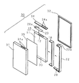
図15に従来の電池パックの一般的な構成例の模式的分解斜視図を示す。電池パックは、直方体状の電池ケース11をそれよりも一回り大きい合成樹脂製の直方体状の外装ケース30に収容したものである。なお、外装ケース30は共に一側面が開放された直方体状の第1外装ケース半体31と第2外装ケース半体32とで構成されている。両外装ケース半体32及び32は開放された一側面の外形寸法が同一に形成されており、開放された一側面同士を対向させて合体させた状態でその内部に電池ケース11及びその他の回路等を収容可能な空洞が形成されるようになっている。
FIG. 15 is a schematic exploded perspective view of a general configuration example of a conventional battery pack. In the battery pack, a rectangular
電池ケース11はアルミニウム又はアルミニウム合金製であり、その内部には正極及び負極をセパレータを介して巻回した発電要素からなる非水電解質二次電池、具体的にはたとえばリチウムイオン二次電池等の二次電池10が収容されている。電池ケース11の一側面(図15では底面)には、電池ケース11とは絶縁された負極端子33が形成されており、この負極端子33が設けられた部分以外の電池ケース全体が正極端子になる。
The
電池ケース11の上述した負極端子33が設けられている一側面に対向する側面(図15では上面)には保護回路基板34が取り付けられる。保護回路基板34は、電池10の過充電又は過放電等を防止するための保護回路が設けられた基板である。保護回路基板34は、電池ケース11と対向する面(図15では下面)に回路素子(図示せず)が実装されており、反対側、即ち電池ケース11に対して外側の面(図15では上面)に、外部へ電力を取り出し、また逆に充電のために外部から電力を取り込むための正負極の電極端子34aが突設されている。また、第1外装ケース半体31の一側面(図15では上面)には、保護回路基板34の出力端子34aが貫通して先端部が若干突出するようにした貫通孔31aが形成されている。
A
保護回路基板34は、ニッケル製の正極リード板20を介して、電池10の正極端子を兼ねる電池ケース11に固着されたクラッド板12に固着される。クラッド板12は、その一方の面が電池ケース11の保護回路基板34が取り付けられる側面に溶接により固着されており、他方の面は正極リード板20に溶接により固着されている。従って、正極リード板20はクラッド板12を介して電池ケース11に固着されていることになる。
The
更に、保護回路基板34は、ニッケル製の負極リード板22及びPTC(Positive Temerature Coefficient)素子28を介して電池10の負極端子33とも接続されている。PTC素子28は、電池10の温度が異常上昇したような場合に温度に感応して高抵抗となることにより、回路を遮断する保護素子である。
Further, the
負極リード板22は電池ケース11の負極端子33が備えられている側面(図15では底面)と保護回路基板34が備えられている側面(図15では上面)の間を接続するために両側面間の一側面(図15では右側面)に沿って設けられている。但し、電池ケース11は負極端子33以外の全体が正極端子を兼ねているので、短絡防止のために負極リード板22及びPTC素子28と電池ケース11との間には絶縁シート16が介装されている。
The negative
保護回路基板34が接続された電池ケース11は、保護回路基板34及び貫通孔31aの向きを合わせて両外装ケース半体31,32を合体させた場合に形成される空洞内に両面粘着テープ35で固定されて収容される。そして、両外装ケース半体31,32同士が接着、熱溶着、又は超音波溶着等で固着されて1個の箱状の容器にされることにより、外装ケース30の貫通孔31aに電極端子34aが突出した電池パックが構成される。通常、商品としてはこの電池パックの状態で流通し、また種々の電子機器にもこのような電池パックの状態で装着される。
The
ところで、ニッケル製の正極リード板20は、負極端子33が形成されている部分以外は全て正極端子を兼ねる電池ケース11にクラッド板12を介して固着されているが、クラッド板12を介する理由は以下による。即ち、電池ケース11に正極リード板20を溶接により直接固着することは、電池ケース11がアルミニウム又はアルミニウム合金製であるので抵抗溶接法では電池ケース11の導電性が良好であることに起因して、また超音波溶接法では正極リード板20がニッケル製(又はステンレス製)であるので溶解しないことに起因して、いずれも不可能であるという理由による。
By the way, the positive
このような事情から、従来は上述のようなクラッド板12を使用せずに電池ケース11に正極リード板20を固着するためにはたとえばレーザ溶接法が検討されていた。しかし、レーザ溶接法を使用する場合には、使用環境条件が著しく規制されると共に、装置が高価であり、しかも生産性が低いために電池(電池パック)の製造コストの高騰を招来するという問題があった。
Under such circumstances, for example, a laser welding method has been studied in order to fix the positive
このような問題点を解決することを目的として上述したような従来技術、即ち電池ケース11に2層構造のクラッド板12のアルミニウム又はアルミニウム合金製の一方の層を抵抗溶接し、クラッド板のニッケル製の他方の層をニッケル製の正極リード板20と抵抗溶接する発明が特許文献1に開示されている。
In order to solve such problems, the conventional technique as described above, that is, one layer made of aluminum or an aluminum alloy of the
図16は図15に示されているクラッド板12の構成例を示す模式図である。図16(a)はクラッド板12の平面形状を示す模式図であり、電池ケース11の保護回路基板34が取り付けられる一側面(図15では上面)の幅よりは狭い幅の矩形の板状の外形を有している。また図16(b)はクラッド板12の側面を示す模式図である。クラッド板12は上述したような2層構成であり、一方の層12aの表面が電池ケース11に溶接され、他方の層12bの表面が正極リード板20に溶接されることにより、電池ケース11に正極リード板20が固着される。
上述した特許文献1に開示されている発明のクラッド板は、いずれか一方の層を電池ケースに抵抗溶接し、他方の層を正極リード板と抵抗溶接するのであるが、当然のことながら逆にはできない。このため、電池パックの組み立てに際してはクラッド板の表裏を間違わないようにする必要があるが、従来は表裏両面の金属光沢の相異を作業員が目視で識別していたため、電池の組立工程において誤判定が生じる可能性があった。
In the clad plate disclosed in
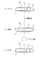
ところで、上述のような電池パックには他にも表裏の識別が要求される構成要素が存在する。それはポリスイッチ等の電子部品に複数のリード板が取り付けられた構成の部品であり、表裏判定を誤って製造した場合には不良品となってしまう。図17はそのようなポリスイッチに複数のリード板が取り付けられた電池パック部品の構成例及び表裏判定が必要な理由を説明するための模式図である。 Incidentally, the battery pack as described above includes other components that require front / back identification. It is a component having a configuration in which a plurality of lead plates are attached to an electronic component such as a polyswitch. If the front / back determination is manufactured incorrectly, it becomes a defective product. FIG. 17 is a schematic diagram for explaining a configuration example of a battery pack component in which a plurality of lead plates are attached to such a polyswitch and the reason why front / back determination is necessary.
図17(a)はポリスイッチに複数のリード板が取り付けられた電池パック部品の構成を示す模式的側面図である。ポリスイッチ51は板状の形状であり、その両面にそれぞれリード板61,62が取り付けられることにより、一つの電池パック部品50を構成している。そしてこのように組み立てられた電池パック部品の一方のリード板62が更に他のリード板63に接続される。この図17(a)に示されているように電池パック部品50が正常にリード板63に接続された状態では、リード板63,同62,ポリスイッチ51,リード板61の順(又は逆順)の回路が構成され、ポリスイッチ51に電流が流れることになる。
FIG. 17A is a schematic side view showing a configuration of a battery pack component in which a plurality of lead plates are attached to a polyswitch. The
しかし、電池パック部品50の表裏が逆の状態でリード板63を接続する装置に送られた場合、図17(b)に示すように、本来はリード板62及びポリスイッチ51を介してリード板63と間接的に接続されるべきリード板61がリード板63に直接接続されるので、ポリスイッチ51には電流が流れなくなる。
However, when the
更に上述のような電池パック部品50に使用されるリード板61,62には他の問題もある。図18はリード板そのものに存在する問題点を説明するための模式的側断面図である。リード板は通常、母材である金属板60から型を使用した打ち抜き加工により製造される。打ち抜き加工では、図18に示す矢符方向に母材である金属板60を打ち抜いた場合にはリード板の面に対して周縁部にほぼ直交方向に突出した「ばり」が形成される。この「ばり」が突出した面が絶縁テープで覆われるようにして電池パックを組み立てると、「ばり」が絶縁テープを突き破って絶縁不良が発生する等の問題も生じる。また帯状の母材を切断する場合にもその切断面に「ばり」が発生することはいうまでもない。
Furthermore, there are other problems with the
本発明はこのような事情に鑑みてなされたものであり、電池ケースと正極リード板とをクラッド板を介して固着する際にクラッド板の表裏を間違うことがないようにした電池の提供を目的とする。 The present invention has been made in view of such circumstances, and an object of the present invention is to provide a battery in which the front and back of the clad plate are not mistaken when the battery case and the positive electrode lead plate are fixed via the clad plate. And
また本発明は上述のような電池に使用されるクラッド材の製造方法を提供することを目的とする。 Another object of the present invention is to provide a method for producing a clad material used in the battery as described above.
更に本発明は、リード板が取り付けられていて表裏を判定する必要がある場合に、容易に表裏を判定することが可能な、またリード板の「ばり」が絶縁不良等の原因とならないようにした電池パック部品及びそのリード板の提供を目的とする。 Furthermore, according to the present invention, when the lead plate is attached and it is necessary to judge the front and back, it is possible to easily judge the front and back, and so that the “flash” of the lead plate does not cause an insulation failure or the like. An object of the present invention is to provide a battery pack component and a lead plate thereof.
また更に本発明は上述のような電池パック部品のリード板の製造方法の提供を目的とする。 Still another object of the present invention is to provide a method for producing a lead plate for a battery pack component as described above.
本発明は端的には、電池ケースに正極リード板を溶接により固着するために両者間に介装される接続部材であるクラッド板の平面形状を表裏が異なる形状を呈し、しかも平面上で回転させても一致しないように構成する。また、電池パック部品に取り付けられるリード板の平面形状を、電子部品に取り付けられた場合の電子部品に対向する側の表面の外形と、電子部品に対向しない側の表面の外形とが平面上で回転させても一致せず、且つ点対称となる形状とする。更にリード板が表裏両面に取り付けられた電池パック部品の平面形状の外形を線対称であり、且つ点対称ではない形状に構成する。 In short, the present invention presents the planar shape of the clad plate, which is a connecting member interposed between the two in order to fix the positive electrode lead plate to the battery case by welding, and has a different shape on the front and back sides, and is rotated on the plane. However, it is configured not to match. In addition, the planar shape of the lead plate attached to the battery pack component is such that the outer shape of the surface facing the electronic component when attached to the electronic component and the outer shape of the surface not facing the electronic component are flat. The shape does not match even when rotated and is point-symmetric. Furthermore, the outer shape of the planar shape of the battery pack component in which the lead plate is attached to both the front and back surfaces is configured to be line symmetric and not point symmetric.
本発明に係る電池の発明は、発電要素を収容した第1金属製の電池ケースと、前記発電要素から電流を取り出す第2金属製の電流取出用リード板とを備え、第1層が前記電池ケースに固着され、第2層が前記電流取出用リード板に固着されたクラッド板により前記電池ケースに前記電流取出用リード板を固着した電池において、前記クラッド板は、前記第1層が前記電池ケースに固着された場合に外面となる第2層側の表面の外形と、前記第2層が前記電池ケースに固着された場合に外面となる第1層側の表面の外形とが平面上で回転させても一致しない形状に構成されていることを特徴とする。 The battery according to the present invention includes a first metal battery case that houses a power generation element, and a second metal current extraction lead plate that extracts current from the power generation element, and the first layer is the battery. A battery in which the current extraction lead plate is fixed to the battery case by a clad plate fixed to the case and a second layer fixed to the current extraction lead plate, wherein the first layer is the battery. The outer shape of the surface on the second layer side that becomes the outer surface when fixed to the case and the outer shape of the surface on the first layer side that becomes the outer surface when the second layer is fixed to the battery case are planar. It is characterized by having a shape that does not match even when rotated.
このような本発明に係る電池の発明では、クラッド板が表裏逆転している場合には、平面状で回転させても、表裏が逆転していない場合の形状と一致しない。 In such a battery invention according to the present invention, when the clad plate is reversed, even if the clad plate is rotated in a plane, it does not match the shape when the front and back are not reversed.
また本発明に係る電池に使用されるクラッド板の製造方法は、発電要素を収容した第1金属製の電池ケースと、前記発電要素から電流を取り出す第2金属製の電流取出用リード板と、第1層が前記電池ケースに固着され、第2層が前記電流取出用リード板に固着されることにより、前記電池ケースに前記電流取出用リード板を固着するためのクラッド板とを備えた電池の前記クラッド板を帯状の母材を連続的に切断して製造する方法において、個々のクラッド板の一方の側の表面の外形と、他方の側の表面の外形とが平面上で回転させても一致しない形状になるような切断線で前記母材を幅方向に横断して切断することを特徴とする。 A method for manufacturing a clad plate used in a battery according to the present invention includes a first metal battery case that houses a power generation element, a second metal current extraction lead plate that extracts current from the power generation element, and A battery including a clad plate for fixing the current extraction lead plate to the battery case by fixing the first layer to the battery case and the second layer to the current extraction lead plate. In the method of manufacturing the clad plate by continuously cutting a strip-shaped base material, the outer shape of the surface on one side of each clad plate and the outer shape of the surface on the other side are rotated on a plane. The base material is cut across the width direction along a cutting line that has a shape that does not match.
このような本発明に係る電池に使用されるクラッド板の製造方法では、上述のクラッド板が、一つの切断線で帯状の母材から切断されるのみにて製造される。 In such a method for manufacturing a clad plate used in a battery according to the present invention, the above-described clad plate is manufactured only by being cut from a strip-shaped base material by one cutting line.
また、本発明に係る電池パック部品のリード板は、電池と共に電池パックの外装ケースに収容される電池パック部品に備えられており、表裏面間を電流が通電する板状の電子部品の表裏面それぞれに取り付けられる電池パック部品のリード板において、前記電子部品に取り付けられた場合の前記電子部品に対向する側の表面の外形と、前記電子部品に対向しない側の表面の外形とが平面上回転させても一致せず、且つ点対称に構成されていることを特徴とする。 In addition, the battery pack component lead plate according to the present invention is provided in the battery pack component housed in the battery pack outer case together with the battery, and the front and back surfaces of the plate-like electronic component in which current flows between the front and back surfaces. In the lead plate of the battery pack component attached to each, the outer shape of the surface facing the electronic component when mounted on the electronic component and the outer shape of the surface not facing the electronic component rotate on a plane. Even if it is made to correspond, it is comprised, and it is comprised by point symmetry.
このような本発明の電池パック部品のリード板では、平面上で180度回転させると同一形状を呈するが、表裏逆転している場合には、平面状で回転させても、表裏が逆転していない場合の形状と一致しない。 Such a lead plate of the battery pack component of the present invention exhibits the same shape when rotated 180 degrees on a plane. However, when the front and back are reversed, the front and back are reversed even if the plane is rotated. Does not match the shape when there is no.
更に本発明に係る電池パック部品の第1の発明は、表裏面間を電流が通電する板状の電子部品の表裏それぞれにリード板が取り付けられ、電池と共に電池パックの外装ケースに収容される電池パック部品において、前記リード板は、前記電子部品に取り付けられた場合の前記電子部品に対向する側の表面の外形と、前記電子部品に対向しない側の表面の外形とが平面上で回転させても一致せず、且つ点対称に構成されており、前記電子部品の表裏それぞれに前記リード板が、前記一方の面同士、又は前記他方の面同士を対向させて線対称に取り付けられていることを特徴とする。 Furthermore, the first invention of the battery pack component according to the present invention is a battery in which a lead plate is attached to each of the front and back surfaces of a plate-like electronic component in which a current flows between the front and back surfaces, and the battery is housed in an outer case of the battery pack together with the battery. In the pack component, the lead plate is configured so that the outer shape of the surface facing the electronic component when mounted on the electronic component and the outer shape of the surface not facing the electronic component are rotated on a plane. And the lead plate is attached to each of the front and back surfaces of the electronic component in line symmetry with the one surface or the other surface facing each other. It is characterized by.
また、本発明に係る電池パック部品の第2の発明は、表裏面間を電流が通電する板状の電子部品の表裏それぞれにリード板が取り付けられ、電池と共に電池パックの外装ケースに収容される電池パック部品において、前記電子部品の表裏面それぞれにリード板が取り付けられた場合の平面形状の外形が線対称であり、且つ点対称ではないことにより、表裏面の外形が異なる形状を呈し、且つ平面上で回転させた場合に表面の外形形状と裏面の外形形状とが一致するように構成されていることを特徴とする。 According to a second aspect of the battery pack component of the present invention, a lead plate is attached to each of the front and back surfaces of a plate-like electronic component that allows current to flow between the front and back surfaces, and is housed in the battery pack outer case together with the battery. In the battery pack component, the outer shape of the planar shape when the lead plate is attached to each of the front and back surfaces of the electronic component is line symmetric and not point symmetric, so that the outer shape of the front and back surfaces is different, and When rotated on a plane, the outer shape of the front surface and the outer shape of the back surface are made to coincide with each other.
このような本発明に係る電池パック部品の第1,第2の発明では、電子部品の表裏面それぞれにリード板が取り付けられた場合の平面形状の外形が線対称であり、且つ点対称ではないので、表裏が反転している場合には異なる形状を呈するが、表裏が反転している状態のままで180度回転した場合には表裏が反転していない場合と同一形状を呈する。 In the first and second aspects of the battery pack component according to the present invention, the outer shape of the planar shape when the lead plate is attached to each of the front and back surfaces of the electronic component is line symmetric and not point symmetric. Therefore, when the front and back are reversed, a different shape is exhibited. However, when the front and back are rotated 180 degrees while being reversed, the same shape as when the front and back are not reversed is exhibited.
更に本発明に係る電池パック部品のリード板の製造方法は、表裏面間を電流が通電する板状の電子部品の表裏それぞれにリード板が取り付けられ、電池と共に電池パックの外装ケースに収容される電池パック部品の前記リード板を帯状の母材を連続的に切断して製造する方法において、個々のリード板の一方の側の表面の外形と他方の側の表面の外形とが平面上では一致せず、且つ点対称となる形状になるような切断線で前記母材を幅方向に横断して切断することを特徴とする。 Furthermore, in the method for manufacturing a lead plate for a battery pack component according to the present invention, a lead plate is attached to each of the front and back surfaces of a plate-like electronic component that allows current to flow between the front and back surfaces, and is housed in the battery pack outer case together with the battery. In the method of manufacturing the lead plate of the battery pack part by continuously cutting a strip-shaped base material, the outer shape of the surface on one side of each lead plate and the outer shape of the surface on the other side coincide on a plane. And the base material is cut across the width direction along a cutting line that has a point-symmetric shape.
このような本発明に係る電池パック部品のリード板の製造方法では、前述の本発明のリード板が一つの切断線で帯状の母材から切断されるのみにて製造される。 In such a method of manufacturing a lead plate for a battery pack component according to the present invention, the above-described lead plate of the present invention is manufactured only by being cut from a strip-shaped base material by one cutting line.
本発明に係る電池の発明によれば、いずれの面が上を向いているかによってクラッド板が異なる平面形状に見えるので、表裏を誤判定する可能性がなくなり、生産効率の向上が期待される。 According to the battery invention of the present invention, the clad plate looks different depending on which surface is facing upward, so there is no possibility of misjudging the front and back, and an improvement in production efficiency is expected.
また本発明に係る電池に使用されるクラッド板の製造方法によれば、個々のクラッド板は一つの切断線で帯状の母材から切断されるのみにて製造されるので、帯状の母材から個々のクラッド板を切断して得る際にいわゆる切り屑が発生しない。従って、クラッド材の切り屑が電池の組立工程に紛れ込んで電気的な短絡等が発生する虞がなくなり、不良品が発生する可能性が低減する。 Moreover, according to the manufacturing method of the clad plate used for the battery according to the present invention, each clad plate is produced by only being cut from the band-shaped base material by one cutting line. When the individual clad plates are cut and obtained, so-called chips are not generated. Therefore, there is no possibility that the chips of the clad material get mixed into the battery assembly process and an electrical short circuit or the like occurs, and the possibility that a defective product is generated is reduced.
また本発明に係る電池パック部品のリード板によれば、表裏が反転している場合には異なる形状を呈するので表裏判定が容易であり、しかも180度回転している場合には同一形状を呈するので電池パック部品への取り付けの際の方向を揃える必要が無いので作業効率が向上する。 Further, according to the lead plate of the battery pack component according to the present invention, when the front and back are reversed, different shapes are presented, so that the front / back determination is easy, and when they are rotated 180 degrees, the same shape is exhibited. Therefore, it is not necessary to align the direction when attaching to the battery pack parts, so that work efficiency is improved.
本発明に係る電池パック部品の第1の発明によれば、いずれの面が上を向いているかによってリード板が異なる平面形状に見えるので、表裏を誤判定する可能性がなくなり、生産効率の向上が期待される。しかも、電池パック部品としての全体の形状も表裏それぞれの面が異なる外形に見えるようになると共に、対称中心点を回転中心として回転させることにより表裏を反転させた場合と同様の結果が得られるので、表裏の判定が容易であり、表裏反転していることが判明した場合にも再度表裏反転指せる必要はなく、平面上で180度回転させるのみにて、正常な状態に戻すことができる。従って、治具への電池パック部品の正常な状態での装着が容易になる。 According to the first aspect of the battery pack component of the present invention, since the lead plate looks different in plan shape depending on which side is facing upward, there is no possibility of misjudging the front and back, and improvement in production efficiency There is expected. In addition, the overall shape of the battery pack component also looks different on the front and back surfaces, and the same result as when the front and back are reversed by rotating around the center of symmetry is obtained. It is easy to determine the front and back, and even when it is found that the front and back are reversed, it is not necessary to turn the front and back again, and the normal state can be restored simply by rotating 180 degrees on the plane. Therefore, the battery pack component can be easily mounted on the jig in a normal state.
更に本発明に係る電池パック部品のリード板の製造方法によれば、個々のリード板は一つの切断線で帯状の母材から切断されるのみにて製造されるので、帯状の母材から個々のリード板を切断して得る際にいわゆる切り屑が発生しない。従って、リード材の切り屑が電池の組立工程に紛れ込んで電気的な短絡等が発生する虞がなくなり、不良品が発生する可能性が低減する。 Furthermore, according to the method for manufacturing a lead plate for a battery pack component according to the present invention, each lead plate is manufactured only by being cut from the strip-shaped base material by one cutting line. When the lead plate is cut and obtained, so-called chips are not generated. Accordingly, there is no possibility that the lead material chips get mixed into the battery assembly process and an electrical short circuit or the like occurs, and the possibility that a defective product is generated is reduced.
また、本発明に係る電池パック部品の第2の発明によれば、表裏が反転している場合には電子部品から突出している部分のリード板の外形が異なる形状を呈するので表裏判定が容易であり、且つ表裏が反転している状態のままで180度回転した場合には表裏が反転していない場合と同一形状を呈するので、表裏を再度反転させることなく平面上で180度回転させるのみにて表裏が反転していない状態に戻すことができるので作業効率が向上する。 Further, according to the second invention of the battery pack component according to the present invention, when the front and back are reversed, the lead plate of the portion protruding from the electronic component has a different shape, so the front and back determination is easy. If it is rotated 180 degrees with the front and back reversed, it will have the same shape as when the front and back are not reversed, so it will only be rotated 180 degrees on the plane without reversing the front and back. Therefore, work efficiency is improved because the front and back sides can be returned to a non-inverted state.
以下、本発明をその実施の形態を示す図面を参照して説明する。なお、電池パック全体の構成は図15に示した従来例と同一である。本発明の電池の構成が図15に示した従来例と異なる点は以下に説明するクラッド板の平面形状のみである。従って、以下においては主としてクラッド板の平面形状について説明する。 Hereinafter, the present invention will be described with reference to the drawings showing embodiments thereof. The overall configuration of the battery pack is the same as that of the conventional example shown in FIG. The configuration of the battery of the present invention is different from the conventional example shown in FIG. 15 only in the planar shape of the clad plate described below. Accordingly, the planar shape of the clad plate will be mainly described below.
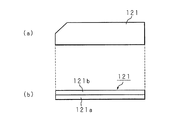
図1は本発明に係る電池に使用されるクラッド板の構成の一例を示す模式図である。なお、この例ではクラッド板を参照符号121で示す。図1(a)はクラッド板121の平面形状を示す模式図であり、電池ケース11の保護回路基板34が取り付けられる一側面(図15では上面)の幅よりは狭い幅の平面視で矩形の一隅部を斜めに切り落とした5角形の板状の外形を有している。この図1(a)に示されているクラッド板121の平面形状は、その長さ方向及び幅方向のいずれに関しても線対称にはなっていない。従って、クラッド板121はその表裏で異なる形状を呈すると共に、表裏逆転した状態で平面上で回転させても表裏逆転していない状態の形状と同一の形状を呈することはあり得ない。
FIG. 1 is a schematic diagram showing an example of the configuration of a clad plate used in a battery according to the present invention. In this example, the clad plate is denoted by
また、図1(b)はクラッド板121の側面を示す模式図である。クラッド板121は2層構成であり、一方の層121aの表面が電池ケース11に溶接され、他方の層121bの表面が正極リード板20に溶接されることにより、電池ケース11に正極リード板20が固着されることは前述の図16に示した従来例と同様である。
FIG. 1B is a schematic view showing a side surface of the
図2は図1に示すクラッド板121を電池ケース11に固着した状態を示す模式的外観斜視図である。図2(a)に示されている状態がクラッド板121が正常に電池ケース11に溶接された(又は、溶接するために載置されている)状態であるとすると、クラッド板121が表裏逆に電池ケース11上に溶接された(又は溶接するために載置されている)場合には図2(b)の模式的外観斜視図に示すように、図2(a)に示した正常な状態に比してクラッド板121の平面形状が明らかに相異するので、表裏の判定が容易になる。
FIG. 2 is a schematic external perspective view showing a state in which the
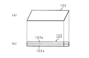
図3は本発明に係る電池に使用されるクラッド板の構成の他の例を示す模式図である。なお、この例ではクラッド板を参照符号122で示す。図3(a)はクラッド板122の平面形状を示す模式図であり、電池ケース11の保護回路基板34が取り付けられる一側面(図15では上面)の幅よりは狭い幅の平面視で平行四辺形の板状の外形を有している。この図3(a)に示されているクラッド板122の平面形状は、その長さ方向及び幅方向のいずれに関しても線対称にはなっていない。従って、クラッド板122はその表裏で異なる形状を呈すると共に、表裏逆転した状態で平面上で回転させても表裏逆転していない状態の形状と同一の形状を呈することはあり得ない。
FIG. 3 is a schematic view showing another example of the configuration of the clad plate used in the battery according to the present invention. In this example, the clad plate is indicated by
また、図3(b)はクラッド板122の側面を示す模式図である。クラッド板122は2層構成であり、一方の層122aの表面が電池ケース11に溶接され、他方の層122bの表面が正極リード板20に溶接されることにより、電池ケース11に正極リード板20が固着されることは前述の図16に示した従来例及び図1に示した本発明の一例と同様である。
FIG. 3B is a schematic view showing a side surface of the
図4は図3に示すクラッド板122を電池ケース11に固着した状態を示す模式的外観斜視図である。図4(a)に示されている状態がクラッド板122が正常に電池ケース11に溶接された(又は、溶接するために載置されている)状態であるとすると、クラッド板122が表裏逆に電池ケース11上に溶接された(又は溶接するために載置されている)場合には図4(b)の模式的外観斜視図に示すように、図4(a)に示した正常な状態に比してクラッド板122の平面形状が明らかに相異するので、表裏の判定が容易になる。
4 is a schematic external perspective view showing a state in which the
図5は本発明に係る電池に使用されるクラッド板の構成の更に他の例を示す模式図である。なお、この例ではクラッド板を参照符号123で示す。図5(a)はクラッド板123の平面形状を示す模式図であり、電池ケース11の保護回路基板34が取り付けられる一側面(図15では上面)の幅よりは狭い幅の平面視で不等脚台形の板状の外形を有している。この図5(a)に示されているクラッド板123の平面形状は、その長さ方向及び幅方向のいずれに関しても線対称にはなっていない。従って、クラッド板123はその表裏で異なる形状を呈すると共に、表裏逆転した状態で平面上で回転させても表裏逆転していない状態の形状と同一の形状を呈することはあり得ない。
FIG. 5 is a schematic view showing still another example of the configuration of the clad plate used in the battery according to the present invention. In this example, the clad plate is denoted by
また、図5(b)はクラッド板123の側面を示す模式図である。クラッド板123は2層構成であり、一方の層123aの表面が電池ケース11に溶接され、他方の層123bの表面が正極リード板20に溶接されることにより、電池ケース11に正極リード板20が固着されることは前述の図16に示した従来例及び図1、図3に示した本発明の例と同様である。
FIG. 5B is a schematic view showing a side surface of the
図6は図5に示すクラッド板123を電池ケース11に固着した状態を示す模式的外観斜視図である。図6(a)に示されている状態がクラッド板123が正常に電池ケース11に溶接された(又は、溶接するために載置されている)状態であるとすると、クラッド板123が表裏逆に電池ケース11上に溶接された(又は溶接するために載置されている)場合には図6(b)の模式的外観斜視図に示すように、図6(a)に示した正常な状態に比してクラッド板123の平面形状が明らかに相異するので、表裏の判定が容易になる。
FIG. 6 is a schematic external perspective view showing a state in which the
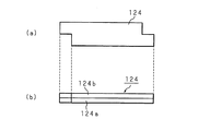
図7は本発明に係る電池に使用されるクラッド板の構成の更に他の例を示す模式図である。なお、この例ではクラッド板を参照符号124で示す。図7(a)はクラッド板124の平面形状を示す模式図であり、電池ケース11の保護回路基板34が取り付けられる一側面(図15では上面)の幅よりは狭い幅の平面視で矩形の対向する2隅部を矩形状に切り取った板状の外形を有している。この図7(a)に示されているクラッド板124の平面形状は、その長さ方向及び幅方向のいずれに関しても線対称にはなっていない。従って、クラッド板124はその表裏で異なる形状を呈すると共に、表裏逆転した状態で平面上で回転させても表裏逆転していない状態の形状と同一の形状を呈することはあり得ない。
FIG. 7 is a schematic view showing still another example of the configuration of the clad plate used in the battery according to the present invention. In this example, the clad plate is indicated by
また、図7(b)はクラッド板124の側面を示す模式図である。クラッド板124は2層構成であり、一方の層124aの表面が電池ケース11に溶接され、他方の層124bの表面が正極リード板20に溶接されることにより、電池ケース11に正極リード板20が固着されることは前述の図16に示した従来例及び図1、図3、図5に示した本発明の例と同様である。
FIG. 7B is a schematic diagram showing a side surface of the
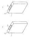
図8は図7に示すクラッド板124を電池ケース11に固着した状態を示す模式的外観斜視図である。図8(a)に示されている状態がクラッド板124が正常に電池ケース11に溶接された(又は、溶接するために載置されている)状態であるとすると、クラッド板124が表裏逆に電池ケース11上に溶接された(又は溶接するために載置されている)場合には図8(b)の模式的外観斜視図に示すように、図8(a)に示した正常な状態に比してクラッド板124の平面形状が明らかに相異するので、表裏の判定が容易になる。
FIG. 8 is a schematic external perspective view showing a state in which the
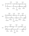
ところで、上述の各例の内の図3及び図4、図5及び図6、図7及び図8にそれぞれ示したクラッド板122、123、124に関しては、フープ(hoop)状、即ち帯状の母材からいわゆる切り屑が生じないようにして製造することが可能である。以下、具体的に説明する。
By the way, regarding the
図9は本発明に係る電池に使用されるクラッド板の製造方法を説明するための模式図である。図9(a)は前述の図3及び図4に示したクラッド板122の製造方法を説明するための模式図である。クラッド材を所定の幅でフープ状にした母材120を、図9(a)に破線にて示すような母材120の長さ方向と斜めに交差する方向の所定間隔で平行な複数の切断線122cで母材120を横断して切断する。これにより、図3(a)にその平行四辺形の平面形状を示したクラッド板122がいわゆる切り屑を生じさせることなしに個々の切断された個片として得られる。
FIG. 9 is a schematic view for explaining a method of manufacturing a clad plate used in the battery according to the present invention. FIG. 9A is a schematic view for explaining a method of manufacturing the
図9(b)は前述の図5及び図6に示したクラッド板123の製造方法を説明するための模式図である。クラッド材を所定の幅でフープ状にした母材120を、図9(b)に破線にて示すような母材120の長さ方向と比較的大なる角度で斜めに交差する方向の所定間隔で平行な複数の切断線123caと、この切断線123caよりはやや小なる角度で母材120の長さ方向と比較的大なる角度で斜めに交差する方向の所定間隔で平行な複数の切断線123cbとで交互に切断する。これにより、図5(a)にその不等脚台形の平面形状を示したクラッド板123がいわゆる切り屑を生じさせることなしに個々の切断された個片として得られる。
FIG. 9B is a schematic view for explaining a method of manufacturing the
図9(c)は前述の図7及び図8に示したクラッド板124の製造方法を説明するための模式図である。クラッド材を所定の幅でフープ状にした母材120を、図9(c)に破線にて示すような母材120の幅方向の中心線の一部の両端から幅方向の両外側へ垂線を下ろした形状の所定間隔の複数の切断線124cで母材120を横断して切断する。これにより、図7(a)にその平面形状を示したクラッド板124がいわゆる切り屑を生じさせることなしに個々の切断された個片として得られる。
FIG. 9C is a schematic diagram for explaining a method of manufacturing the
なお、クラッド板の平面形状としては上述しような形状に限らず、線対称ではない形状であれば、種々の形状が可能であることはいうまでもない。 Needless to say, the planar shape of the clad plate is not limited to the shape described above, and various shapes are possible as long as the shape is not line-symmetric.
次に本発明の電池パック部品について、主としてそれに取り付けられるリード板の平面形状及びそれが両面に取り付けられた場合の電池パック部品全体の形状について説明する。 Next, regarding the battery pack component of the present invention, the planar shape of the lead plate attached to the battery pack component and the shape of the entire battery pack component when it is attached to both surfaces will be described.
なお、本発明の電池パック部品においては、それに取り付けられるリード板が従来は主として金属板の母材から打ち抜き加工により得られるため一方の面に「ばり」が突出しており、この「ばり」がリード板が取り付けられた電池パック部品が電池パックに組み込まれた後に絶縁テープ等を突き破って絶縁不良を生じるという問題を解決するために、リード板そのものの表裏判定が容易であること、更には電池パック部品の本体の表裏にリード板が取り付けられた状態で電池パック部品の全体としての表裏判定が容易であることを目的としている。 In the battery pack component of the present invention, since the lead plate attached to the battery pack component is conventionally obtained by punching from a base metal plate, a “flash” protrudes on one side, and this “flash” is the lead. In order to solve the problem that after the battery pack component with the plate attached is assembled in the battery pack, the insulation tape is broken to cause insulation failure, it is easy to determine the front and back of the lead plate itself. The object is to make it easy to determine the front and back of a battery pack component as a whole in a state where lead plates are attached to the front and back of the main body of the component.
図10(a)は本発明のリード板の平面形状の一例を示す模式図である。このリード板61は線対称ではないが点対称の形状に平面形状の外形が形成されており、金属板の母材から打ち抜き加工により得られる。従って、このようなリード板61の一方の面には「背景技術」の項において説明した如く「ばり」が形成されている。以下においてはリード板61の「バリ」が形成されている面を裏面、「ばり」が形成されていない面を表面という。
FIG. 10A is a schematic diagram showing an example of the planar shape of the lead plate of the present invention. The
図10(b)は図10(a)に示したリード板61を表裏反転した状態を示す模式図である。このリード板61は線対称ではない外形の平面形状を有するように構成されているので、このように表面(「ばり」が突出していない面)と裏面(「ばり」が突出している面)とでは、平面上ではどのような操作をしても、たとえば平面上で180°回転させたとしても、図10(a)に示す表面の形状と一致することはない明らかに異なる形状を呈する。
FIG. 10B is a schematic diagram showing a state in which the
従って、この図10に示したような線対称ではない外形の平面形状を有するリード板61を電池パック部品の本体であるポリスイッチ51の表裏にそれぞれ取り付ける際には表裏を判定することが容易である。しかも、図10に示すリード板61はその平面形状の外形が点対称に構成されているので、図10(a)に示す状態を平面上で180度回転させた場合には同一の形状を呈することになる。従って、リード板61をたとえばポリスイッチ51に取り付ける際には180度回転している状態であってもよいので、作業効率が向上する。
Therefore, it is easy to determine the front and back when attaching the
なお、万一、リード板61,62のいずれかの表裏を間違ってポリスイッチ51に取り付けてしまった場合にも、容易に判定可能である。即ち、図11(a),(b)は図10に示した形状のリード板61と、これと同一形状であるリード板62とを電池パック部品の本体であるポリスイッチ51の表裏にそれぞれ取り付けた本発明の電池パック部品50の外観を示す模式的斜視図である。但し、図11(a),(b)においては、リード板61,62は共に裏側(「ばり」が突出している面)をポリスイッチ51に面して、換言すれば両リード板61は相互に裏面を対向させた状態でポリスイッチ51に取り付けられており、この状態が正しい状態である。
It should be noted that even if one of the
この図11(b)に示す電池パック部品50の平面形状は、リード板61(62)が線対称ではないが点対称である外形形状を有しているので、全体としては中心線CLに対して線対称となる。
The planar shape of the
しかし、たとえばポリスイッチ51の裏面側のリード板62の表裏を間違ってしまった場合、図11(c),(d)に示すように、リード板61(62)が左右に延長された状態の平面形状を呈することになるので、電池パック部品50全体としての平面形状が線対称ではない(但し、点対称にはなる)形状を呈する。従って、電池パック部品50の全体としての形状が図11(b)に示す正常な状態とは明らかに異なる形状を呈するので、容易に判定可能になる。
However, for example, if the front and back of the
このように、ポリスイッチ51の表面に取り付けられているリード板61はバリが突出している面をポリスイッチ51側に面して(図上で奥側にして)ポリスイッチ51に取り付けられており、ポリスイッチ51の裏面に取り付けられているリード板62もバリが突出している面をポリスイッチ51側に面して(図上で手前側にして)ポリスイッチ51に取り付けられている。従って、このような本発明の電池パック部品50が従来例と同様の電池10と共に外装ケース30に収容された場合には両リード板61,62の「ばり」がポリスイッチ51を挟んで内側をむいているので、絶縁テープ等を突き破る虞はなく、絶縁不良の原因となることを防止することが可能である。
In this way, the
次に、図10にその外形形状が示されているリード板61(62)を例に、そのようなリード板61(62)が相互に裏面を対向させてポリスイッチ51に取り付けられた状態の電池パック部品50の表裏判定の容易性について説明する。
Next, taking the lead plate 61 (62) whose outer shape is shown in FIG. 10 as an example, such a lead plate 61 (62) is attached to the polyswitch 51 with the back surfaces facing each other. The ease of front / back determination of the
図12は図11(a)に示す構成の本発明の電池パック部品の表裏判定の容易性及び表裏反転している場合に元の状態に戻すことが容易であることを説明するための模式図である。具体的には、図12(a)は図11(b)と同様の図であり、本発明の電池パック部品50の正常な状態、即ちポリスイッチ51の両面にリード板61及び62がそれぞれの裏面(「ばり」が突出している面)を対向させて取り付けられている状態を示す模式的平面図である。この場合、両リード板61,62そのものは線対称ではない(但し、点対称ではある)同一の形状であるが、ポリスイッチ51の中心線(CL)を対称中心として線対称になるようにポリスイッチ51に取り付けられているので、電池パック部品50全体としては線対称であるが点対称ではない外形形状を呈する。
FIG. 12 is a schematic diagram for explaining the ease of front / back determination of the battery pack component of the present invention having the configuration shown in FIG. 11 (a) and the ease of returning to the original state when the front / back is reversed. It is. Specifically, FIG. 12 (a) is the same diagram as FIG. 11 (b), in which the
ところで、図12(a)に示す状態が本発明の電池パック部品50が組立工程の治具に装着される正常な状態であるとすると、この電池パック部品50そのものが表裏逆に治具に装着された場合には図12(b)に示すような状態で治具に装着されることになる。この場合、両リード板61,62それぞれの端部の形状が正常な状態である図12(a)とは明らかに異なる形状を呈するため、作業員の目視でも、またたとえば光学センサ等による自動判定でも、電池パック部品50の表裏を容易に判定することが可能である。
By the way, if the state shown in FIG. 12A is a normal state in which the
しかも、上述の図12(b)に示した例では、電池パック部品50を正常な状態に戻すためには電池パック部品50そのものの表裏を反転させて、即ち裏返しにして図11(a)に示す状態にする作業が不要である。具体的には、図12(b)に示されている、正常な状態とは表裏逆の状態の電池パック部品50をたとえば180°回転させたとすると図12(c)に示すような状態になる。
In addition, in the example shown in FIG. 12B described above, in order to return the
即ち、両リード板61,62の形状が点対称であるので、その点対称の中心点(線対称の中心線上にある)を回転中心として180度回転させれば図12(b)に示す状態から図12(c)に示す状態になり、これは正常な状態である図12(a)に示す状態と同一の外形形状である。従って、ポリスイッチ51の表裏両面に取り付けられるリード板が線対称ではないが点対称の外形形状に構成されている場合には、図12(a),(b),(c)に示すように、電池パック部品50の表裏が逆である場合にも、電池パック部品50を表裏反転させる(裏返す)ことなしに、平面上で単に180度回転させれば正常な状態に戻せることになり、作業員の人手による場合であっても、また機械的な操作による場合であっても、電池パック部品50の表裏を反転させる(裏返しにする)場合に比して容易な作業であることは明らかである。
That is, since the shape of both the
なお、リード板61(62)の平面形状としては前述した図10に示されているような形状に限らず、線対称ではなくしかも点対称であれば、種々の形状が可能であることはいうまでもない。 Note that the planar shape of the lead plate 61 (62) is not limited to the shape shown in FIG. 10 described above, and various shapes are possible as long as they are not line-symmetric and point-symmetric. Not too long.
たとえば、前述の本発明のクラッド板の形状の内の図3(a)及び図7(a)に示した外形の平面形状等であってもよい。このような図3(a)及び図7(a)に示したクラッド板と同様の形状のリード板は、従来同様に金属板の打ち抜き加工により製造することも勿論可能であるが、前述したクラッド板と同様にそれぞれ図9(a)及び(c)に示した方法と同様にして母材であるフープ状(帯状)の金属板を適宜の間隔で連続的に切断して製造することも可能である。 For example, the shape of the clad plate of the present invention described above may be the planar shape of the outer shape shown in FIGS. 3A and 7A. Such a lead plate having the same shape as the clad plate shown in FIGS. 3A and 7A can of course be manufactured by punching a metal plate as in the prior art. Similarly to the plate, it is possible to manufacture by continuously cutting the hoop-shaped (strip-shaped) metal plate as the base material at an appropriate interval in the same manner as the method shown in FIGS. 9 (a) and (c). It is.
図13(a)及び(b)は上述した図3(a),図7(a)に示したクラッド板の形状と同一の外形の平面形状を有するように構成したリード板611,621及び612,622をポリスイッチ51の両面に取り付けた電池パック部品50の構成例を示す模式的斜視図である。また、図14は図13(b)に示す構成の電池パック部品50の表裏判定の容易性及び表裏反転している場合に元の状態に戻すことが容易であることを説明するための模式的斜視図である。
13A and 13B show
図14に示す例においても、前述の図12に示した例と同様にポリスイッチ51の一面(表面)にリード板612が、他面(裏面)にリード板622がそれぞれ取り付けられているが、両リード板612,622は共に線対称ではないが点対称である外形の平面形状を有する同一の平面形状に構成されており、しかもポリスイッチ51の中心線(CL)を対称中心として線対称になるようにポリスイッチ51の表裏面にそれぞれ取り付けられている。
In the example shown in FIG. 14 as well, the
そして、ポリスイッチ51の表面に取り付けられているリード板612はバリが突出している面をポリスイッチ51側に面して(図上で奥側にして)ポリスイッチ51に取り付けられており、ポリスイッチ51の裏面に取り付けられているリード板622もバリが突出している面をポリスイッチ51側に面して(図上で手前側にして)ポリスイッチ51に取り付けられていることも前述の図12に示した例と同様である。従って、このような本発明の電池パック部品50が従来例と同様の電池10と共に外装ケース30に収容された場合に、両リード板612,622の「ばり」が絶縁テープ等を突き破る虞はないので、絶縁不良の原因となることを防止することが可能であることも前述同様である。
The
ところで、図14(a)に示す状態が本発明の電池パック部品50が組立工程の治具に装着される正常な状態であるとすると、この電池パック部品が表裏逆に治具に装着された場合には図14(b)に示すような状態で治具に装着されることになる。この場合、両リード板612,622それぞれの端部の形状が正常な状態である図14(a)とは明らかに異なる形状を呈するため、作業員の目視でも、またたとえば光学センサによる判定でも、容易に表裏が逆であることが判定可能であることも前述同様である。
By the way, if the state shown in FIG. 14 (a) is a normal state in which the
しかし、この図14(b)に示した例では、両リード板612,622の形状が点対称であるので、その点対称の中心点(線対称の中心線上にある)を回転中心として180度回転させれば図14(c)に示す平面形状を呈するようになる。この図14(c)に示す状態は電池パック部品50が正常に治具に装着された場合の図14(a)に示す状態と同一の状態である。従って、ポリスイッチ51の表裏両面に取り付けられるリード板が前述同様に線対称ではないが点対称である外形の平明形状に構成されている場合には、図14(a),(b),(c)に示すように、電池パック部品50の表裏を反転させる(裏返す)ことなしに、平面上で単に180度回転させれば正常な状態に戻せることになり、作業員の人手による場合であっても、また機械的な操作による場合であっても、電池パック部品50の表裏を反転させる(裏返しにする)場合に比して容易な作業であることは明らかである。
However, in the example shown in FIG. 14B, the shape of both the
このように、電池パック部品50のポリスイッチ51に取り付けられるリード板は線対称ではないが点対称である外形の平面形状を有していればよく、上述した以外にも種種の形状に構成することが可能であることはいうまでもない。
As described above, the lead plate attached to the
更に、リード板そのものの形状には拘わらず、電池パック部品50として構成された状態、具体的にはポリスイッチ51の表裏両面にそれぞれリード板が取り付けられた状態の電池パック部品50全体としての外形形状が線対称であり且つ点対称でない形状であれば上述同様の効果を得ることが可能である。たとえば図1(a)の模式図に示したクラッド板材121は線対称でもなく点対称でもない外形形状に構成されているが、このような形状のリード板を使用しても電池パック部品50全体の外形形状としては図12に示す電池パック部品50と同様の外形形状を有するように構成するが可能である。
Further, regardless of the shape of the lead plate itself, the outer shape of the
この場合、個々のリード板は同一形状であるが表裏逆に母材から打ち抜いたリード板を組み合わせてポリスイッチ51の表裏両面に取り付けることにより、「ばり」が突出している面を相互に対向させた状態でリード板をポリスイッチ51の表裏両面に取り付けることが可能である。更に、「ばり」を研磨加工等により削除するか、またはレーザカット工法等のような「ばり」が生じない工法により製造すれば、同一形状のリード板を表裏反転してポリスイッチ51の表裏両面に取り付けるようにしてもよい。
In this case, each lead plate has the same shape, but the lead plates punched out from the base material are combined and attached to both the front and back surfaces of the polyswitch 51 so that the surfaces from which the “burrs” protrude are opposed to each other. In this state, the lead plates can be attached to both the front and back surfaces of the
また上述の実施の形態においては本発明の電池パック部品としてポリスイッチ51の表裏両面にリード板が取り付けられている部品を例としたが、これに限るのものではなく、板状の本体の表裏両面にリード板が取り付けられている部品であれば本発明を適用することが可能である。
Further, in the above-described embodiment, the battery pack component of the present invention is an example in which lead plates are attached to both the front and back surfaces of the
10 電池
11 電池ケース
12(121〜124) クラッド板
12a(121a〜124a) クラッド板の一方の層
12b(121b〜124b)クラッド板の他方の層
122c〜124c 切断線
50 電池パック部品
51 ポリスイッチ
61(611,612) リード板
62(621,622) リード板
DESCRIPTION OF
Claims (6)
前記クラッド板は、前記第1層が前記電池ケースに固着された場合に外面となる第2層側の表面の外形と、前記第2層が前記電池ケースに固着された場合に外面となる第1層側の表面の外形とが平面上で回転させても一致しない形状に構成されていることを特徴とする電池。 A first metal battery case containing a power generation element; and a second metal current extraction lead plate for taking out current from the power generation element, wherein the first layer is fixed to the battery case, and the second layer is In the battery in which the lead plate for current extraction is fixed to the battery case by the clad plate fixed to the lead plate for current extraction,
The clad plate has an outer shape of a surface on the second layer side that becomes an outer surface when the first layer is fixed to the battery case, and a first surface that becomes an outer surface when the second layer is fixed to the battery case. A battery characterized in that the outer shape of the surface on the one-layer side does not coincide even when rotated on a plane.
個々のクラッド板の一方の側の表面の外形と、他方の側の表面の外形とが平面上で回転させても一致しない形状になるような切断線で前記母材を幅方向に横断して切断することを特徴とする電池に使用されるクラッド板の製造方法。 A first metal battery case containing the power generation element, a second metal current extraction lead plate for taking out current from the power generation element, a first layer is fixed to the battery case, and a second layer is the current Manufacturing by continuously cutting a band-shaped base material of the battery including the cladding plate for fixing the current extraction lead plate to the battery case by being fixed to the extraction lead plate In the way to
Crossing the base material in the width direction with a cutting line such that the outer shape of the surface on one side of each clad plate and the outer shape of the surface on the other side do not match even if rotated on a plane A method for producing a clad plate used for a battery, characterized by cutting.
前記電子部品に取り付けられた場合の前記電子部品に対向する側の表面の外形と、前記電子部品に対向しない側の表面の外形とが平面上で回転させても一致せず、且つ点対称に構成されていることを特徴とする電池パック部品のリード板。 In the lead plate of the battery pack component that is provided in the battery pack component housed in the battery pack outer case together with the battery, and is attached to each of the front and back surfaces of the plate-shaped electronic component through which current flows between the front and back surfaces,
The outer shape of the surface facing the electronic component when attached to the electronic component and the outer shape of the surface not facing the electronic component do not match even when rotated on a plane, and are point-symmetric A lead plate for battery pack parts, characterized in that it is configured.
前記リード板は、前記電子部品に取り付けられた場合の前記電子部品に対向する側の表面の外形と、前記電子部品に対向しない側の表面の外形とが平面上で回転させても一致せず、且つ点対称に構成されており、
前記電子部品の表裏それぞれに前記リード板が、前記一方の面同士、又は前記他方の面同士を対向させて線対称に取り付けられていること
を特徴とする電池パック部品。 In the battery pack parts that are attached to the front and back of the plate-like electronic parts that conduct current between the front and back surfaces, and are housed in the battery pack outer case together with the battery,
When the lead plate is attached to the electronic component, the outer shape of the surface facing the electronic component and the outer shape of the surface not facing the electronic component do not match even when rotated on a plane. And is configured point-symmetrically,
The battery pack component according to claim 1, wherein the lead plates are attached to the front and back surfaces of the electronic component in line symmetry with the one surface or the other surface facing each other.
個々のリード板の一方の側の表面の外形と他方の側の表面の外形とが平面上では一致せず、且つ点対称となる形状になるような切断線で前記母材を幅方向に横断して切断することを特徴とする電池パック部品のリード板の製造方法。 Lead plates are attached to the front and back sides of the plate-shaped electronic component that conducts current between the front and back surfaces, and the battery pack component lead plate housed in the battery pack outer case together with the battery is continuously formed with a strip-shaped base material. In the method of cutting and manufacturing,
The outer shape of the surface of one side of each lead plate and the outer shape of the surface of the other side do not coincide with each other on the plane, and the base material is crossed in the width direction by a cutting line that becomes a point-symmetric shape. And cutting the battery pack component lead plate.
前記電子部品の表裏面それぞれにリード板が取り付けられた場合の平面形状の外形が線対称であり、且つ点対称ではないことにより、表裏面の外形が異なる形状を呈し、且つ平面上で回転させた場合に表面の外形形状と裏面の外形形状とが一致するように構成されていることを特徴とする電池パック部品。 In the battery pack parts that are attached to the front and back of the plate-like electronic parts that conduct current between the front and back surfaces, and are housed in the battery pack outer case together with the battery,
When the lead plate is attached to each of the front and back surfaces of the electronic component, the outer shape of the planar shape is line symmetric and not point symmetric, so that the outer shapes of the front and back surfaces are different and are rotated on the plane. The battery pack component is configured so that the outer shape of the front surface and the outer shape of the back surface coincide with each other.
Priority Applications (1)
| Application Number | Priority Date | Filing Date | Title |
|---|---|---|---|
| JP2004104392A JP2005293919A (en) | 2004-03-31 | 2004-03-31 | Battery, and manufacturing method of clad plate used for the battery, and manufacturing method of lead plate of battery pack parts and battery pack parts and lead plate |
Applications Claiming Priority (1)
| Application Number | Priority Date | Filing Date | Title |
|---|---|---|---|
| JP2004104392A JP2005293919A (en) | 2004-03-31 | 2004-03-31 | Battery, and manufacturing method of clad plate used for the battery, and manufacturing method of lead plate of battery pack parts and battery pack parts and lead plate |
Publications (1)
| Publication Number | Publication Date |
|---|---|
| JP2005293919A true JP2005293919A (en) | 2005-10-20 |
Family
ID=35326639
Family Applications (1)
| Application Number | Title | Priority Date | Filing Date |
|---|---|---|---|
| JP2004104392A Pending JP2005293919A (en) | 2004-03-31 | 2004-03-31 | Battery, and manufacturing method of clad plate used for the battery, and manufacturing method of lead plate of battery pack parts and battery pack parts and lead plate |
Country Status (1)
| Country | Link |
|---|---|
| JP (1) | JP2005293919A (en) |
Cited By (5)
| Publication number | Priority date | Publication date | Assignee | Title |
|---|---|---|---|---|
| US8020423B2 (en) | 2007-06-21 | 2011-09-20 | Metal Industries Research & Development Centre | Electronic casing and method of manufacturing the same |
| JP2013229125A (en) * | 2012-04-24 | 2013-11-07 | Toyota Industries Corp | Battery module and vehicle |
| JP2017091723A (en) * | 2015-11-06 | 2017-05-25 | 株式会社豊田自動織機 | Method of manufacturing electricity storage device, and electricity storage device |
| CN115911733A (en) * | 2021-09-30 | 2023-04-04 | 比亚迪股份有限公司 | Battery |
| JP2025513038A (en) * | 2022-04-22 | 2025-04-22 | エルジー エナジー ソリューション リミテッド | Electrode leads and correspondingly shaped lead input palettes |
-
2004
- 2004-03-31 JP JP2004104392A patent/JP2005293919A/en active Pending
Cited By (6)
| Publication number | Priority date | Publication date | Assignee | Title |
|---|---|---|---|---|
| US8020423B2 (en) | 2007-06-21 | 2011-09-20 | Metal Industries Research & Development Centre | Electronic casing and method of manufacturing the same |
| JP2013229125A (en) * | 2012-04-24 | 2013-11-07 | Toyota Industries Corp | Battery module and vehicle |
| JP2017091723A (en) * | 2015-11-06 | 2017-05-25 | 株式会社豊田自動織機 | Method of manufacturing electricity storage device, and electricity storage device |
| CN115911733A (en) * | 2021-09-30 | 2023-04-04 | 比亚迪股份有限公司 | Battery |
| JP2025513038A (en) * | 2022-04-22 | 2025-04-22 | エルジー エナジー ソリューション リミテッド | Electrode leads and correspondingly shaped lead input palettes |
| JP7842245B2 (en) | 2022-04-22 | 2026-04-07 | エルジー エナジー ソリューション リミテッド | Electrode leads and corresponding lead input pallets |
Similar Documents
| Publication | Publication Date | Title |
|---|---|---|
| JP2001256937A (en) | Battery pack and battery pack | |
| WO2003069698A1 (en) | Battery and method of manufacturing the battery | |
| WO2006046343A1 (en) | Battery pack | |
| WO2003056643A1 (en) | Battery pack | |
| CN100440586C (en) | Non-welding contact type secondary battery | |
| CN101378111A (en) | Conduction lug and battery including the same | |
| JP2009231145A (en) | Secondary battery | |
| KR102409424B1 (en) | Battery module, manufacturing method the same | |
| JP2001060457A (en) | Pressure-sensitive breaker for battery | |
| US12597673B2 (en) | Battery pack and electronic device | |
| JP2005293919A (en) | Battery, and manufacturing method of clad plate used for the battery, and manufacturing method of lead plate of battery pack parts and battery pack parts and lead plate | |
| JP4622502B2 (en) | battery | |
| CN117855553A (en) | Battery cell and method of manufacturing the same | |
| CN102447082A (en) | Battery package body | |
| JP2006107808A (en) | Battery connection member | |
| JP2002050884A (en) | Circuit board and method of connecting this circuit board to a rechargeable battery | |
| KR101223733B1 (en) | Electrode connector and battery module using the same | |
| CN114696045A (en) | Battery cell pole group, lithium ion battery and pole lug welding method | |
| US20230076491A1 (en) | Battery pack and electronic device | |
| JP2003168408A (en) | Battery pack | |
| JP4326381B2 (en) | battery | |
| KR20010008762A (en) | Lithium polymer secondary battery | |
| JP2012186058A (en) | Circuit board with lead and battery pack | |
| JP2001325939A (en) | Connection structure between flat battery and protection circuit board | |
| JP2007200630A (en) | Battery pack, method of assembling the same, and portable electronic device using the same |