JP2005293907A - Battery pressure member for film exterior battery - Google Patents
Battery pressure member for film exterior battery Download PDFInfo
- Publication number
- JP2005293907A JP2005293907A JP2004104109A JP2004104109A JP2005293907A JP 2005293907 A JP2005293907 A JP 2005293907A JP 2004104109 A JP2004104109 A JP 2004104109A JP 2004104109 A JP2004104109 A JP 2004104109A JP 2005293907 A JP2005293907 A JP 2005293907A
- Authority
- JP
- Japan
- Prior art keywords
- battery
- film
- clad
- shearing
- support portion
- Prior art date
- Legal status (The legal status is an assumption and is not a legal conclusion. Google has not performed a legal analysis and makes no representation as to the accuracy of the status listed.)
- Granted
Links
Images


Classifications
-
- Y—GENERAL TAGGING OF NEW TECHNOLOGICAL DEVELOPMENTS; GENERAL TAGGING OF CROSS-SECTIONAL TECHNOLOGIES SPANNING OVER SEVERAL SECTIONS OF THE IPC; TECHNICAL SUBJECTS COVERED BY FORMER USPC CROSS-REFERENCE ART COLLECTIONS [XRACs] AND DIGESTS
- Y02—TECHNOLOGIES OR APPLICATIONS FOR MITIGATION OR ADAPTATION AGAINST CLIMATE CHANGE
- Y02E—REDUCTION OF GREENHOUSE GAS [GHG] EMISSIONS, RELATED TO ENERGY GENERATION, TRANSMISSION OR DISTRIBUTION
- Y02E60/00—Enabling technologies; Technologies with a potential or indirect contribution to GHG emissions mitigation
- Y02E60/10—Energy storage using batteries
Landscapes
- Battery Mounting, Suspending (AREA)
Abstract
【課題】フィルム外装電池を自動車に積載して使用するのに適した、伸縮量に対して過度に反力が変化しないフィルム外装電池用の電池加圧部材を提供する。
【解決手段】電池加圧部材1は、複数のゴムバネ2と、ゴムバネ2を嵌め込み溝11にて保持するゴムバネ固定部材10とを有する。ゴムバネ2は、フィルム外装電池31に当接する当接部5と、その両端に形成された支持部3と、両端の各支持部3と当接部5とを接続し、剪断変形する剪断部4とを有する。各支持部3の外側面3bには、嵌め込み溝11からの脱落防止用の突起部6が形成されている。
【選択図】図1
Disclosed is a battery pressure member for a film-clad battery, which is suitable for loading a film-clad battery in an automobile and whose reaction force does not change excessively with respect to the amount of expansion and contraction.
A battery pressure member includes a plurality of rubber springs and a rubber spring fixing member that holds the rubber springs in a fitting groove. The rubber spring 2 includes a contact portion 5 that contacts the film-clad battery 31, support portions 3 formed at both ends thereof, and a shear portion 4 that connects the support portions 3 and the contact portions 5 at both ends and shears and deforms. And have. On the outer surface 3 b of each support portion 3, a projection portion 6 for preventing the drop from the fitting groove 11 is formed.
[Selection] Figure 1
Description
本発明は、フィルム外装電池を所定の範囲内の反力にて固定保持するフィルム外装電池用の電池加圧部材に関するものである。 The present invention relates to a battery pressure member for a film-clad battery that fixes and holds the film-clad battery with a reaction force within a predetermined range.
近年、モータ駆動用のバッテリを搭載する電気自動車やハイブリッド電気自動車(以下、単に「電気自動車等」ともいう)の開発が急速に進められつつある。電気自動車等に搭載される電池にも、操舵特性、航続距離を向上させるため、当然ながら、軽量、薄型化が求められている。電池を軽量かつ薄型とするため、その外装体にアルミニウムなどの金属層と熱溶着性の樹脂層とを接着剤層を介して重ね合わせて薄いフィルムとなしたラミネート材を用いたフィルム外装電池電池が開発されている。ラミネート材は、一般に、アルミニウム等の薄い金属層の両表面を薄い樹脂層で被覆した構造をなしており、酸やアルカリに強く、かつ軽量で柔軟な性質を有するものである。 In recent years, the development of electric vehicles and hybrid electric vehicles (hereinafter also simply referred to as “electric vehicles etc.”) equipped with a battery for driving a motor has been rapidly advanced. Of course, batteries mounted on electric vehicles and the like are also required to be light and thin in order to improve steering characteristics and cruising distance. In order to make the battery lightweight and thin, a film-clad battery battery using a laminate material in which a metal layer such as aluminum and a heat-weldable resin layer are overlapped with an outer layer through an adhesive layer to form a thin film Has been developed. In general, a laminate material has a structure in which both surfaces of a thin metal layer such as aluminum are covered with a thin resin layer, and is resistant to acids and alkalis, and is lightweight and flexible.
一般に、電池の特性は、充放電時における正極と負極の活物質の膨張収縮の影響を受ける。よって、従来、金属製の容器に収納して変形を抑制している。しかしながら、フィルム外装電池の場合、外装のラミネートフィルムによって電池の膨らみを抑制することは殆どできない。このため、電池に適正な荷重をかけて固定することで電池の膨らみを抑制する構成が必要となる。 In general, the characteristics of a battery are affected by the expansion and contraction of the active material of the positive electrode and the negative electrode during charging and discharging. Therefore, it is conventionally housed in a metal container to suppress deformation. However, in the case of a film-clad battery, the swelling of the battery can hardly be suppressed by the laminated film of the exterior. For this reason, the structure which suppresses the swelling of a battery by applying an appropriate load to a battery is needed.
このため、電池の膨張を抑制するために、例えば、正極および負極がセパレータを介して積層された電極群を有する有機電解質二次電池において、積層された電極群を、断面形状がコの字状であって、向かい合う2つの面の内側にそれぞれ複数の突起を有する押さえ部材に収納したことを特徴とする有機電解質二次電池が開示されている(特許文献1等参照)。
Therefore, in order to suppress the expansion of the battery, for example, in an organic electrolyte secondary battery having an electrode group in which a positive electrode and a negative electrode are stacked via a separator, the stacked electrode group has a U-shaped cross section. However, an organic electrolyte secondary battery characterized in that it is housed in a pressing member having a plurality of protrusions on the insides of the two surfaces facing each other is disclosed (see
一方、自動車に組電池化されたフィルム外装電池が搭載される場合は、一般に組電池を収納容器内に収納固定して用いられるが、この収納容器としては軽量、絶縁性等が要求されるため樹脂性のものが用いられる。収納容器の樹脂には膨張係数の小さい樹脂が選択して用いられるが、使用環境が−40℃〜80℃と過酷であるため、僅かではあるが膨張収縮を生じてしまい、電池への荷重に影響を与えてしまうこととなる。特に、収納容器を構成する樹脂が熱膨張すると電池に印加する荷重圧が所定の荷重圧より減ってしまい、電池の特性を十分に引き出すことができなくなるという問題を生じる場合がある。 On the other hand, when a film-clad battery made into an assembled battery is mounted on an automobile, the assembled battery is generally stored and fixed in a storage container. However, the storage container is required to be lightweight, insulating, and the like. A resinous material is used. A resin with a small expansion coefficient is selected and used as the resin for the storage container. However, since the usage environment is harsh, such as -40 ° C to 80 ° C, expansion and contraction occur slightly, resulting in a load on the battery. Will be affected. In particular, when the resin constituting the storage container is thermally expanded, the load pressure applied to the battery is reduced below a predetermined load pressure, which may cause a problem that the characteristics of the battery cannot be sufficiently extracted.
このように、電池自身あるいは収納容器の膨張収縮により電池にかかる荷重は変動する。この荷重変動を吸収して所定の範囲内に収めるために、従来、固定部材の材料としてゴム等の弾性部材が用いられる。 Thus, the load applied to the battery varies due to the expansion or contraction of the battery itself or the storage container. Conventionally, an elastic member such as rubber is used as a material for the fixing member in order to absorb the load variation and fall within a predetermined range.
自動車用のフィルム外装電池における電池固定用弾性部材については、以下の要求がある。
1)低硬度であること、すなわち、低バネ定数であること
2)反発力が所望の変位において、できるだけ鈍いこと
3)狭い空間(薄い製品形状高さ、例えば2〜6mm)の中に設置する
4)面圧がばらつかないこと
5)電池の周辺に用いるため、電気的絶縁に優れていること
6)万が一、電解液が漏れた場合に悪影響を及ぼさないこと
7)連続使用において、反力の変化が小さいこと
8)自動車に使うことから温度は−40℃〜80℃の範囲で機能し、劣化が少
ないこと
9)振動に対しても電池を守る機能を示すこと(緩衝機能を有すること)
10)低コストであること
従来、これらの要件を満たすべく、電池固定用弾性部材として低硬度のゴムを圧縮して用いる方法が採用されていた。
1) Low hardness, that is, low spring constant 2) Repulsive force is as dull as possible at the desired displacement 3) Install in a narrow space (thin product shape height, eg 2-6 mm) 4) Surface pressure does not vary 5) It is used around the battery, so it has excellent electrical insulation 6) Should there be no adverse effect if the electrolyte leaks 7) Reaction force in continuous use 8) Because it is used in automobiles, the temperature functions in the range of -40 ° C to 80 ° C, and there is little deterioration. 9) It shows a function to protect the battery against vibration (having a buffer function). )
10) Low cost Conventionally, in order to satisfy these requirements, a method of compressing and using low-hardness rubber as an elastic member for fixing a battery has been employed.
しかしながら、いくら低硬度のゴムとはいえ、圧縮ではその反力が圧縮変形量に比べて急激に立ち上がることは既知である。すなわち、2)反発力が所望の変位において、できるだけ鈍いこと、という要件を十分に満足することができない。このため、低硬度ゴムを用いて電池を固定したとしても、ゴムの圧縮作用によって荷重変動を吸収して所定の範囲内に収めようとする方法では、電池自身あるいは収納容器の膨張収縮によるゴムのわずかな変位で電池に対する反力が大きく変化してしまい、所望の荷重範囲内にて電池を固定するのが困難であった。 However, although it is a rubber having a low hardness, it is known that the reaction force rises more rapidly than the amount of compressive deformation in compression. That is, 2) the requirement that the repulsive force is as dull as possible at the desired displacement cannot be fully satisfied. For this reason, even if the battery is fixed using low-hardness rubber, the method of absorbing the load fluctuation by the compression action of the rubber and keeping it within a predetermined range causes the rubber itself to expand or shrink due to the expansion or contraction of the storage container. A slight displacement greatly changes the reaction force against the battery, making it difficult to fix the battery within a desired load range.
以上の問題を回避するため、電池固定用の弾性部材としてコイルスプリングを用いることも考えられる。しかしながら、金属製のコイルスプリングの場合、コイルスプリングの端部により電池を損傷してしまうおそれとともに、5)の電気的絶縁性を確保しにくいため、採用は困難である。 In order to avoid the above problem, it is also conceivable to use a coil spring as an elastic member for fixing the battery. However, in the case of a metal coil spring, the end of the coil spring may damage the battery, and it is difficult to ensure the electrical insulation of 5).
また、発泡ウレタン等を用いても同様の機能を満たすことができるが、設置スペースや耐久性の問題より、1)〜10)の全ての要件を満たすことは困難である。 Moreover, although the same function can be satisfy | filled even if foaming urethane etc. are used, it is difficult to satisfy | fill all the requirements of 1) -10) from the problem of installation space or durability.
そこで、本発明は、フィルム外装電池を自動車に積載して使用するのに適した、安定した荷重を印加することができるフィルム外装電池用の電池加圧部材を提供することを目的とする。 Then, an object of this invention is to provide the battery pressurization member for film-clad batteries which can apply the stable load suitable for loading and using a film-clad battery in a motor vehicle.
上記目的を達成するため、発明者らは、ゴムに剪断応力を印加した場合のバネ定数に着目した。 In order to achieve the above object, the inventors focused on the spring constant when a shear stress is applied to the rubber.
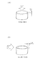
ゴムのバネ定数とストロークの関係は、圧力を圧縮する方向に印加する場合と剪断変形させる方向に印加する場合とでは異なり、圧縮によるバネ定数kcと、剪断によるバネ定数ksとの関係は形状係数をαとすると、一般に
ks=kc/5α
の関係がある。つまり、図6(a)および図6(b)に示すように、ゴム部材に、力Fを剪断力として印加した場合のゴム部材の伸縮量Δx2(図6(b))は、圧縮力として印加した場合の伸縮量Δx1(図6(a))に比べて大きくなる。
本発明は、このようなゴムの静特性を利用したものである。
The relationship between the rubber spring constant and the stroke differs depending on whether the pressure is applied in the compressing direction or the shearing direction. The relationship between the spring constant k c due to compression and the spring constant k s due to shear is If the shape factor is α, generally k s = k c / 5α
There is a relationship. That is, as shown in FIGS. 6A and 6B, when the force F is applied to the rubber member as a shearing force, the expansion / contraction amount Δx 2 of the rubber member (FIG. 6B) is the compressive force. Is larger than the amount of expansion Δx 1 (FIG. 6A).
The present invention utilizes such static characteristics of rubber.
すなわち、本発明のフィルム外装電池用の電池加圧部材は、複数の正極板と複数の負極板とを積層させてなる電池要素を外装体フィルムにより封止したフィルム外装電池を所定の範囲内の反力にて固定保持するフィルム外装電池用の電池加圧部材であって、前記フィルム外装電池に当接し、前記フィルム外装電池から受ける荷重の方向に移動可能な当接部と、前記当接部が移動しても前記荷重の方向には移動しないように設けられる支持部と、前記当接部と前記支持部とを接続し、前記当接部の移動により剪断変形する剪断部と、を有する非導電性のゴム部材を有するものである。 That is, the battery pressurizing member for a film-clad battery according to the present invention includes a film-clad battery in which a battery element formed by laminating a plurality of positive plates and a plurality of negative plates is sealed with a packaging film within a predetermined range. A battery pressure member for a film-clad battery that is fixed and held by a reaction force, abutting part that abuts on the film-clad battery and is movable in the direction of a load received from the film-clad battery, and the abutting part And a support portion provided so as not to move in the direction of the load even if it moves, and a shearing portion that connects the contact portion and the support portion and shears and deforms by the movement of the contact portion. It has a non-conductive rubber member.
上記のとおりの本発明のフィルム外装電池用の電池加圧部材は、当接部で受けた荷重により剪断部を剪断変形させるので、同じ荷重であっても圧縮変形によるものより、バネ定数を小さくすることができる。すなわち、当接部の移動量に対する反力変化量を小さくすることができる構成となっている。これにより、フィルム外装電池が膨張収縮等の変形を起こしたとしてもフィルム外装電池に対して所定の範囲内で荷重を印加することができる。 The battery pressurizing member for a film-clad battery of the present invention as described above shears and deforms the shearing portion by the load received at the contact portion, so that the spring constant is smaller than that due to compression deformation even at the same load. can do. That is, the reaction force change amount with respect to the movement amount of the contact portion can be reduced. Thereby, even if the film-covered battery undergoes deformation such as expansion and contraction, a load can be applied to the film-covered battery within a predetermined range.
また、本発明のフィルム外装電池用の電池加圧部材の支持部は、当接部に両側に配置されているものであってもよい。 Moreover, the support part of the battery pressurization member for film-clad batteries of this invention may be arrange | positioned at the contact part on both sides.
また、本発明のフィルム外装電池用の電池加圧部材の当接部は、支持部および剪断部で形成される面から、フィルム外装電池が配置される方向に突出した突出部を有するものであってもよい。この構成により、フィルム外装電池の所望の位置に反力、すなわち、荷重を印加することができる。 In addition, the contact portion of the battery pressure member for the film-clad battery of the present invention has a protruding portion that protrudes in the direction in which the film-clad battery is arranged from the surface formed by the support part and the shearing part. May be. With this configuration, a reaction force, that is, a load can be applied to a desired position of the film-clad battery.
また、本発明のフィルム外装電池用の電池加圧部材において、支持部の横断面の断面積が剪断部の横断面の断面積以上であってもよく、さらに支持部の横断面の法線方向長さを、剪断部の横断面に対する法線方向であって、剪断部から当接部の荷重がかかる点までの長さ以下とするものであってもよい。この構成により、剪断部をより剪断変形しやすくすることができる。 In the battery pressurizing member for a film-clad battery of the present invention, the cross-sectional area of the support section may be equal to or greater than the cross-sectional area of the shear section, and the normal direction of the cross-section of the support section The length may be a normal direction with respect to the cross section of the shearing portion, and may be equal to or shorter than the length from the shearing portion to the point where the load of the contact portion is applied. With this configuration, the shearing portion can be more easily deformed by shearing.
また、本発明のフィルム外装電池用の電池加圧部材は、支持部からの力を受けてゴム部材を保持する保持部が設けられた固定部材を有するものであってもよい。また、保持部は溝形状であり、支持部が嵌合されて保持されるものであってもよい。このような構成とすることで、当接部が受けた荷重により支持部が移動等することなく、安定した反力を発生することができる。 Moreover, the battery pressurizing member for a film-clad battery of the present invention may have a fixing member provided with a holding portion that receives a force from the support portion and holds the rubber member. Further, the holding portion may be a groove shape, and the support portion may be fitted and held. With such a configuration, it is possible to generate a stable reaction force without the support portion moving due to the load received by the contact portion.
また、本発明のフィルム外装電池用の電池加圧部材において、当接部は、支持部および剪断部で形成される面から、フィルム外装電池が配置される方向に突出した突出部を有し、保持部には、保持部から突出部のみが突出するように支持部が嵌合されるものであってもよい。 Further, in the battery pressurizing member for the film-clad battery of the present invention, the contact part has a protruding part that protrudes in the direction in which the film-clad battery is arranged from the surface formed by the support part and the shearing part, A support part may be fitted to the holding part so that only the protruding part protrudes from the holding part.
また、本発明のフィルム外装電池用の電池加圧部材は、支持部の側面に少なくとも1つの突起部が形成されているものであってもよい。支持部が溝形状の保持部に嵌め込まれることで、突起部が部分的に圧入状態となり、保持部からゴム部材が脱落するのを防止することができる。 Moreover, the battery pressurizing member for a film-clad battery of the present invention may have at least one protrusion formed on the side surface of the support portion. When the support portion is fitted into the groove-shaped holding portion, the protruding portion is partially press-fitted, and the rubber member can be prevented from falling off the holding portion.
本発明によれば、当接部、支持部および剪断部を有するゴム部材の剪断部を剪断変形させて、フィルム外装電池に対して反力、すなわち荷重を与えるので、当接部の移動量に対する反力変化量を小さくすることができる。これにより、フィルム外装電池を過酷な使用条件である自動車に搭載した場合であっても、所定の範囲内で安定した荷重を印加することができる。 According to the present invention, the shearing portion of the rubber member having the contact portion, the support portion, and the shearing portion is subjected to shear deformation, and a reaction force, that is, a load is applied to the film-covered battery. The amount of reaction force change can be reduced. Thereby, even if it is a case where the film-clad battery is mounted in the automobile which is a severe use condition, a stable load can be applied within a predetermined range.
次に、本発明の実施の形態について図面を参照して説明する。 Next, embodiments of the present invention will be described with reference to the drawings.
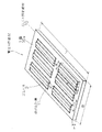
図1は本実施形態のフィルム外装電池用の電池加圧部材の外観斜視図である。図2は、本実施形態の電池加圧部材の構成部材であるゴムバネの三面図であり、図2(a)は正面図、図2(b)は側面図、図2(c)は平面図である。図3は、フィルム外装電池の外観斜視図である。 FIG. 1 is an external perspective view of a battery pressing member for a film-clad battery according to this embodiment. 2A and 2B are three views of a rubber spring, which is a constituent member of the battery pressing member of the present embodiment. FIG. 2A is a front view, FIG. 2B is a side view, and FIG. It is. FIG. 3 is an external perspective view of the film-clad battery.
まず、図1に示す電池加圧部材1の構成について説明する。
First, the configuration of the
本実施形態の電池加圧部材1は、複数のゴムバネ2と、ゴムバネ2を嵌め込み溝11にて保持するゴムバネ固定部材10とを有する。図1に示す例では、1枚のゴムバネ固定部材10に、長手方向に2列、短手方向に3列、それぞれ同形状の嵌め込み溝11が計6つ形成されている。ゴムバネ2は、EPDM(エチレンプロピレンゴム)からなり、圧縮永久歪率が25%以下のものが用いられており、10%以下であるとより好適である。ゴムバネ固定部材10はナイロンからなり、いずれも非導電性を有する。なお、フィルム外装電池31に印加する面圧は、本実施形態の場合、後述するように、1.47±0.49N/cm2であるが、この変動幅がこれよりも大きければ、圧縮永久歪率を25%以上とするものであってもよい。
The
ゴムバネ固定部材10の寸法は、長さL=190mm、幅W=89mm、厚さT=7mmである。また、各嵌め込み溝11の寸法は、全て、長さl=66mm、幅w=20mm、深さd=4mmとしており、短手方向には配列ピッチP1=25mm、長手方向にはP2=10mmの間隔を空けて形成されている。
The rubber
ゴムバネ2は、図2(a)に示すように、フィルム外装電池31に当接する当接部5と、その両端に形成された支持部3と、両端の各支持部3と当接部5とを接続し、剪断変形する剪断部4とを有し、剪断部4は、境界面4aで支持部3の内側面3aに接続し、境界面4bで当接部5に接続している。また、支持部3、剪断部4、当接部5は一体的に形成されており、各支持部3の外側面3bには、嵌め込み溝11からの脱落防止用の突起部6がそれぞれ3個ずつ形成されている。
As shown in FIG. 2A, the
本実施形態の場合、ゴムバネ2は、長さl1=65mm、幅w1=20mmであり、各部寸法は以下の通りである。
In the case of this embodiment, the
支持部3は、支持部3の高さh1(支持部3の横断面(後述)に対する法線方向長さ)=4mm、支持部3の幅w2=4mm、支持部3の内側面3aの高さh2=2mmである。剪断部4は長さl2=3.5mm、厚さt1=2mmである。
The
当接部5は、厚さt2=4mm、幅w3=5mm、突出高さh3=2mmである。
The
すなわち、本実施形態のゴムバネ2は、当接部5に荷重が印加された際に、その荷重を支持部3および当接部5の圧縮変形よりも剪断部4の剪断変形にて吸収させるべく、以下の設定としている。
That is, when a load is applied to the
剪断部4の断面積A4(剪断部4の横断面:本実施形態の場合、A4=t1×l1=2mm×65mm=130mm2)を支持部3の断面積A3(支持部3の横断面:本実施形態の場合、A3=w2×l1=4mm×65mm=260mm2)より小さくなるように設定している。
Sectional area of the shear section 4 A 4 (cross section of the shearing unit 4: In the present embodiment, A 4 = t 1 × l 1 = 2mm × 65mm = 130mm 2) cross-sectional area A 3 of the supporting part 3 (
また、剪断部4の境界面4aから当接部5の荷重がかかる点までの距離l3(剪断部4の横断面に対する法線方向であって、剪断部4から当接部5の荷重がかかる点までの長さ:本実施形態の場合、l3=w2/2+l2=2mm+3.5mm=5.5mm)を、支持部3の高さ(本実施形態の場合、h1=4mm)より長くなるように設定している。
Further, the distance l 3 from the
また、本実施形態のゴムバネ2は嵌め込み溝11内に支持部3の外側面3bが嵌め込み溝11の側面11aに密着するようにして嵌め込むことで、当接部5に荷重が印加された際に、支持部3が内側に倒れ込むのを防止している。すなわち、支持部3の外側面3bの下端角部3b’が側面11aに当接することで下端角部3b’が浮き上がったり、あるいは下端角部3a’が嵌め込み溝11の底面11bを擦りながら移動しないようにしている。
Further, the
また、ゴムバネ2は、支持部3の外側面3bが嵌め込み溝11の側面11aに密着するようにして嵌め込み溝11に嵌め込まれることで、支持部3および剪断部4はゴムバネ固定部材10の主面10aと面一となり、また、当接部5の突出部5aが主面10aより突出するようになっている(図5等参照)。そして、当接部5は、その上面5cでフィルム外装電池31の面31aに当接領域5c’で当接し、フィルム外装電池31からの荷重を矢印A方向に受ける。
Further, the
以上のような構造のゴムバネ2を嵌め込み溝11に嵌め込んで用いることで、概ね両端固定支持の梁構造としている。すなわち、後述するように、当接部5に荷重が印加されると、この荷重を剪断部4の剪断変形により吸収するようにしている。
The
突起部6は、幅4mm、高さ2mm、突出量0.1mmで、ピッチ28mmで形成されている。この突起部6が形成されていることにより、ゴムバネ2を嵌め込み溝11に嵌め込んだ際に部分的に圧入状態となり、嵌め込み溝11からのゴムバネ2の脱落を防止することができる。なお、突出量は0.1〜0.5mmの範囲とするのが好適である。
The
次に、図2に示す、本実施形態に適用可能なフィルム外装電池について説明する。 Next, the film-clad battery applicable to this embodiment shown in FIG. 2 will be described.
フィルム外装電池31は、複数の正極板と複数の負極板とを、セパレータを介して交互に積層して構成されている不図示の電池要素と、電池要素に設けられた不図示の正極集電部および負極集電部と、電池要素を電解液とともに収納する、2枚のラミネートフィルム32からなる外装体と、正極集電部に接続された正極リード端子33aと、負極集電部に接続された負極リード端子33bとを有する。
The film-clad
各正極板はアルミニウム箔に正極電極が塗布されており、負極は銅箔に負極電極が塗布されており、積層領域から延出している、電極材料が塗布されていない延出部は、正極板の延出同士、および負極板の延出部同士がそれぞれ一括して超音波溶接されて、中継部である正極集電部および負極集電部が形成され、各集電部正極リード端子33aおよび負極リード端子33bがそれぞれ超音波溶接にて接合されている。
Each positive plate has a positive electrode applied to an aluminum foil, a negative electrode has a negative electrode applied to a copper foil, and extends from the laminated region. Of the negative electrodes and the extended portions of the negative electrode plates are collectively ultrasonically welded to form a positive current collecting portion and a negative current collecting portion which are relay portions, and each of the current collecting portion
外装体は、電池要素をその厚み方向両側から挟んで包囲する2枚のラミネートフィルム32からなる。各ラミネートフィルム32は、熱融着性を有する熱融着性樹脂層、金属層、および保護層を積層してなるものであり、PP(ポリプロピレン)からなる熱融着性樹脂層が電池の内側の層となるようにしてラミネートフィルム32の熱融着部34を熱融着することで、電池要素が封止される。
The exterior body is composed of two
ラミネートフィルム32としては、電解液が漏洩しないように電池要素を封止できるものであれば、この種のフィルム外装電池に用いられるフィルムを用いることができ、一般的には、金属薄膜層と熱融着性樹脂層とを積層したラミネートフィルムが用いられる。この種のラミネートフィルムとしては、例えば、厚さ10μm〜100μmの金属箔に厚さ3μm〜200μmの熱融着性樹脂を貼りつけたものが使用できる。金属箔、すなわち、金属層の材質としては、Al、Ti、Ti系合金、Fe、ステンレス、Mg系合金などが使用できる。熱融着性樹脂、すなわち、熱融着性樹脂層としては、ポリプロピレン、ポリエチレン、これらの酸変成物、ポリフェニレンサルファイド、ポリエチレンテレフタレートなどのポリエステル等、ポリアミド、エチレン−酢酸ビニル共重合体などが使用できる。また、保護層としては、ナイロン等が好適である。
As the
フィルム外装電池31の電池要素を収納している部分の寸法は、ラミネートフィルム32の部分で長手方向120mm、幅方向80mmである。よって、電池要素を収納している部分の面積は98cm2となる。また、フィルム外装電池一個当たりの重量は、200g〜250gである。
The dimensions of the portion of the film-clad
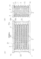
以上のような構成のフィルム外装電池31を組電池化し、電池加圧部材1により保持した状態を図4に示す。図4(a)は正面図であり、図4(b)は側面図である。
FIG. 4 shows a state in which the film-clad
図4に示すフィルム外装電池31は、放熱部材20を介して積層され、一方のフィルム外装電池31の正極リード端子33aを、他方のフィルム外装電池31の負極リード端子33bに電気的に接続する(図4(a)中破線で示す接続部33c)ことで直列接続し、放熱部材20を間に挟み込んで積層することで組電池化している。
The film-clad
このように積層されて組電池化されたフィルム外装電池31を、上下より2枚の電池加圧部材1にて挟み込む。2枚の電池加圧部材1は4隅が連結部材22にて互いに連結されている。この連結部材22は、2枚の電池加圧部材1の間隔を調整可能に設けられており、例えば、ボールネジであってもよい。連結部材22により2枚の電池加圧部材1の間隔を調整することで、ゴムバネ2の当接部5がフィルム外装電池31の面31aに押しつけられ(図3に示す面31aの当接領域5c’に当接部5が当接する)、ゴムバネ2の当接部5が嵌め込み溝11内に押し込まれようとする。これにより、フィルム外装電池31はゴムバネ2からの反力を受けることで所定の荷重がかかり固定保持されることとなる。
Thus, the film-clad
なお、ゴムバネ2の反力によるフィルム外装電池31への荷重の大きさの調整方法は、連結部材22の長さを調整する方法に限定されるものではない。例えば、電池加圧部材1にて挟み込んだ組電池化されたフィルム外装電池31を不図示の容器内に収納し、この容器に備えられた圧力印加手段を用いるものであってもよい。この圧力印加手段としては、例えば、容器の蓋と組電池の最上面に配された電池加圧部材1との間隔を調整するボールネジ等機械的に圧力を印加するものであってもよいし、あるいは、油圧、空気圧等を用いて圧力を印加するものであってもよい。
In addition, the adjustment method of the magnitude | size of the load to the film-clad
また、2枚の電池加圧部材1により上下から挟み込む構成以外に、上部あるいは下部の一方にのみ電池加圧部材1を用い、他方はゴムバネ2を備えていない板部材としてフィルム外装電池31に荷重を印加する構成としてもよい。
In addition to the configuration in which the two
また、ゴムバネ2の当接部5を底面11bに底付きさせた状態を基準に初期設定しておき、フィルム外装電池31が膨らむ方向は容器で加圧し、縮む方向はゴムバネ2で加圧する構成としてもよい。
In addition, the
次に、ゴムバネ固定部材10の嵌め込み溝11内に固定されたゴムバネ2に荷重が印加された場合のゴムバネ2の挙動について図5を用いて説明する。なお、印加される荷重は、電池加圧部材1によってフィルム外装電池31に所望の荷重圧を印加することができる程度の大きさであり、より具体的には1.47±0.49N/cm2の範囲内(0.98〜1.96N/cm2、電池要素を収納している部分の面積は98cm2を考慮すると、96.1N〜192.2Nの範囲内)である。なお、電池を上下方向に積層する場合は、電池の自重がかかることとなる。なお、フィルム外装電池31の積層枚数としては、10〜33枚の範囲が好適であり、特に、10、11、20、22、30、33枚とするものであってもよい。
Next, the behavior of the
図5(a)に示す無負荷状態のゴムバネ2に対して、図5(b)に示すように、当接部5の上面5cに対して矢印A方向(当接部5の上面5cの法線方向であって、上面5cに向かう方向)に荷重が印加されるとする。
For the
フィルム外装電池31のラミネートフィルム32は上述したように、アルミニウムなどの金属フィルムと熱融着性の樹脂フィルムとを重ね合わせて形成したものであるため、力が加わると容易に変形する。よって、上面5cには実際には矢印A方向より僅かに傾斜して荷重が印加されることとなる。しかしながら、当接部5の断面形状は、このように上面5cに対して斜めに荷重が印加された場合であっても当接部5自身が屈曲しないように幅および高さが設定されている。このため、図5(b)に示すように、当接部5はその形状を保持したまま概ね矢印A方向に移動する。
As described above, the
当接部5の矢印A方向への移動に伴い、当接部5が、剪断部4を介して支持部3の上端側を当接部5側へと引っ張り込み、これにより支持部3は内側に倒れようとする。すなわち、支持部3には下端角部3a’を中心として回転しようとする偶力が作用する。しかし、支持部3は上述したように外側面3bが嵌め込み溝11の側面11aに密着するようにして嵌め込まれているので内側には倒れ込まない。また、本実施形態のゴムバネ2は、剪断部4の断面積A4を支持部3の断面積A3より小さく、また、境界面4aから当接部5の荷重がかかる点までの距離l3を支持部3の高さより長くなるように設定されている。
As the
このため、印加される荷重の作用は、当接部5および支持部3を圧縮変形させる圧縮力としての作用よりも剪断部4を剪断変形させる剪断力としての作用が支配的となる。つまり、剪断部4は、当接部5が矢印A方向に荷重を受けて矢印A方向に移動することで当接部5との境界面である境界面4bは矢印A方向に移動し、一方、支持部3との境界面である境界面4aは矢印A方向には移動せず、その場に留まるため、図5(b)のように剪断変形することとなる。
For this reason, the effect | action of the applied load becomes dominant by the effect | action as a shear force which carries out the shear deformation of the
以上のような構成とすることで、以下の効果を得ることができる。 With the above configuration, the following effects can be obtained.
ゴム部材を剪断変形させた際のバネ定数は圧縮変形の際のバネ定数に比べて小さい。換言すれば、ゴム部材の剪断変形量に対する反力変化量は、ゴム部材の圧縮変形量に対する反力変化量に比べて小さい。本実施形態の電池加圧部材1は、上述したようにしてゴムバネ2をゴムバネ固定部材10の嵌め込み溝11にて保持することで剪断部4を剪断変形させ、これにより、当接部5の移動量に対するゴムバネ2の反力変化量が小さくなるようにしている。
The spring constant when the rubber member is subjected to shear deformation is smaller than the spring constant during compression deformation. In other words, the reaction force change amount with respect to the shear deformation amount of the rubber member is smaller than the reaction force change amount with respect to the compression deformation amount of the rubber member. The
このような特性を有する電池加圧部材1によってフィルム外装電池31を保持することで、フィルム外装電池31自身が充放電によって膨張した場合、あるいは収納容器が環境温度の変化により膨張収縮した場合でも、フィルム外装電池31に印加する荷重の変化量を小さくすることができる。
By holding the film-clad
また、本実施形態のゴムバネ2は、当接部5の上面5cに対して矢印A方向に荷重が印加された場合であっても、下端角部3a’が底面11bを擦りながら移動しないようにしている。すなわち、当接部5の上面5cに対して矢印A方向に荷重が印加された場合、支持部3は内側に倒れようとするが、この際、下端角部3a’を中心に回転するような挙動を示すか、あるいは支持部3は内側に倒れ込みながら下端角部3a’が外側にずれ動くといった挙動を示すこととなる。そして、下端角部3a’が底面11bを擦りながら移動する場合、下端角部3a’と底面11bとが引っ掛かったり、あるいはこの引っ掛かりが解除されて大きく滑ったりしながら下端角部3a’が底面11b上を外側に移動することが予測される。このような挙動は、ゴムバネ2によってフィルム外装電池31に与える反力を急激に変化させてしまう要因となる。しかしながら本実施形態のゴムバネ2は、支持部3は上述したように外側面3bが嵌め込み溝11の側面11aに密着するようにして嵌め込まれているので下端角部3a’が底面11bを擦りながら移動することはなく、よって、フィルム外装電池31に所望の反力を安定して与えることができるという効果も得られる。
Further, the
本実施形態のフィルム外装電池用の電池加圧部材は、上述した構成以外に以下のような構成とするものであってもよい。 The battery pressurizing member for a film-clad battery of the present embodiment may have the following configuration in addition to the configuration described above.
本実施形態ではゴムバネ2として、支持部3、剪断部4、および当接部5が一体的に形成されたEPDM等からなる弾性部材を例に示したが、本発明はこれに限定されるものではなく、剪断部4のみがEPDM等の弾性部材であって、その他の支持部3および当接部5は金属、樹脂等からなるものであってもよい。なお、支持部3および当接部5が金属の場合、樹脂等でコーティングして電気的絶縁処理を施しておくのが好ましい。また、剪断部4と、支持部3および当接部5とを別部材で構成する場合、境界面4a、4bは、荷重方向(例えば、図5に示す矢印A方向)に略並行となるように構成すると好適である。
In the present embodiment, an elastic member made of EPDM or the like in which the
本実施形態ではゴムバネ2を長手方向に2列、短手方向に3列配列した例を示したが、これに限定されるものではない。例えば、ゴムバネ2の長手方向がゴムバネ固定部材10の短手方向と略並行になるようし、ゴムバネ固定部材10の長手方向に6列並べるものであってもよい。すなわち、ゴムバネ2の寸法、配置に関しては特に限定されるものではない。
In the present embodiment, an example in which the rubber springs 2 are arranged in two rows in the longitudinal direction and three rows in the short direction is shown, but the present invention is not limited to this. For example, six rows may be arranged in the longitudinal direction of the rubber
また、本実施形態のゴムバネ2は剪断変形する部位のほとんどが剪断部4となる構成を一例に示したが、ゴムバネの変形が圧縮変形よりも剪断変形が支配的となる構成であればどのようなものであってもよい。例えば、ゴムバネの支持部も剪断変形する構成とするものであってもよい。すなわち、本実施形態のゴムバネ2は、剪断部4の横断面である断面積A4を、支持部3の横断面である断面積A3より小さく、また、境界面4aから当接部5の荷重がかかる点までの距離l3を、支持部3の高さh1より長くなるように設定した例を示したが、例えば、断面積A4を断面積A3より大きく、また、距離l3を高さh1より短くなるようにしてもよい。また、断面積A4と断面積A3とを同じにし、また、距離l3と高さh1とを同じにしてもよい。この他、これらの関係を組み合わせて用いてもよい。すなわち、本実施形態の場合、これら寸法を変更することで容易にバネ定数、反力を変更することができる。
In addition, the
また、本実施形態の電池加圧部材1は、ゴムバネ2を嵌め込み溝11にて保持し、かつ下端角部3a’を中心に支持部3が回転しない構造とすることで、ゴムバネ2の剪断部4を両端が略固定支持された梁構造として用いる例を示したが、本発明はこれに限定されるものではなく、両端が自由端とするものであってもよい。例えば、本実施形態のゴムバネ2の形状と概ね同形状の構成とする場合、支持部3の下面を平面形状とするのではなく、下面に頂部を設け、そして、この頂部を嵌め込み溝11の底面11bに形成した溝に嵌め込んでおく。このような構成とすることで支持部3は頂部を中心に回転可能に保持され、かつ、この頂部がずれ動くこともなく、両端を自由端とする梁構造とすることができる。一般に、両端が自由端の梁構造とした場合、両端を固定端とした場合に比べ、同一の荷重を梁の中心にかけた場合、最大撓み量が4倍になることが知られている。よって、当接部5の移動量に対してゴムバネ2の反力の変化量、すなわち、バネ定数をさらに小さくしたい場合には好適である。なお、両端が自由端とする構成は上述したものに限定されるものではなく、剪断部4が概ね両端が自由端となる構造であればどのようなものであってもよい。
Further, the
また、本実施形態の電池加圧部材1は、ゴムバネ2とゴムバネ固定部材10とを別部材として構成した例を示したが、これに限定されるものではなく、一体的に構成されているものであってもよい。
Moreover, although the
また、本実施形態の電池加圧部材1は、ゴムバネ2の当接部5がフルストロークし、当接部5の下面が嵌め込み溝11の底面11bに底付きした場合、当接部5の上面5cはゴムバネ固定部材10の主面10aと面一となる構成を一例に示したが、本発明はこれに限定されるものではなく、当接部5の下面が底付きしても当接部5の上面5cがゴムバネ固定部材10の主面10aより突出する構成とするものであってもよい。
Further, the
また、本実施形態の電池加圧部材1は、ゴムバネ2を溝形状の嵌め込み溝11にて保持する構造を一例に示したが、これに限定されるものではなく、嵌め込み溝11は、その底面11bを支持部3を保持する部分のみを残した貫通穴形状としてもよい。当接部5のストローク量を稼ぎたく、かつゴムバネ固定部材10の板厚を増加させたくない場合に好適である。
Moreover, although the
なお、本実施形態における説明で示した数値、材質等は一例であり、これらに限定されるものではない。 In addition, the numerical value, material, etc. which were shown by description in this embodiment are examples, and are not limited to these.
1 電池加圧部材
2 ゴムバネ
3 支持部
3a 内側面
3b 外側面
3a’、3b’ 下端角部
4 剪断部
4a、4b 境界面
5c 上面
5 当接部
5c’ 当接領域
6 突起部
10 ゴムバネ固定部材
10a 主面
11 嵌め込み溝
11a 側面
11b 底面
20 放熱部材
22 連結部材
31 フィルム外装電池
31a 面
32 ラミネートフィルム
33a 正極リード端子
33a 正極リード端子
33c 接続部
34 熱融着部
A3、A4 断面積
F 荷重、力
kc、ks バネ定数
l3 距離
P1 配列ピッチ
W、w、w1、w2、w3 幅
Δx1、Δx2 伸縮量
α 形状係数
DESCRIPTION OF
Claims (9)
前記フィルム外装電池に当接し、前記フィルム外装電池から受ける荷重の方向に移動可能な当接部と、
前記当接部が移動しても前記荷重の方向には移動しないように設けられる支持部と、
前記当接部と前記支持部とを接続し、前記当接部の移動により剪断変形する剪断部と、を有する非導電性のゴム部材を有するフィルム外装電池用の電池加圧部材。 Battery pressurizing member for a film-clad battery for fixing and holding a film-clad battery in which a battery element formed by laminating a plurality of positive plates and a plurality of negative plates is sealed with a reaction film within a predetermined range Because
Abutting portion that abuts on the film-covered battery and is movable in a direction of a load received from the film-covered battery;
A support portion provided so as not to move in the direction of the load even if the contact portion moves;
A battery pressurizing member for a film-clad battery having a non-conductive rubber member having a shearing part that connects the abutting part and the support part and shears and deforms by movement of the abutting part.
Priority Applications (1)
| Application Number | Priority Date | Filing Date | Title |
|---|---|---|---|
| JP2004104109A JP4632683B2 (en) | 2004-03-31 | 2004-03-31 | Battery pressure member for film exterior battery |
Applications Claiming Priority (1)
| Application Number | Priority Date | Filing Date | Title |
|---|---|---|---|
| JP2004104109A JP4632683B2 (en) | 2004-03-31 | 2004-03-31 | Battery pressure member for film exterior battery |
Publications (2)
| Publication Number | Publication Date |
|---|---|
| JP2005293907A true JP2005293907A (en) | 2005-10-20 |
| JP4632683B2 JP4632683B2 (en) | 2011-02-16 |
Family
ID=35326629
Family Applications (1)
| Application Number | Title | Priority Date | Filing Date |
|---|---|---|---|
| JP2004104109A Expired - Fee Related JP4632683B2 (en) | 2004-03-31 | 2004-03-31 | Battery pressure member for film exterior battery |
Country Status (1)
| Country | Link |
|---|---|
| JP (1) | JP4632683B2 (en) |
Cited By (9)
| Publication number | Priority date | Publication date | Assignee | Title |
|---|---|---|---|---|
| JP2009517823A (en) * | 2005-12-02 | 2009-04-30 | ルノー・エス・アー・エス | Power generation module having a plurality of electrochemical cells |
| JP2009529218A (en) * | 2006-03-06 | 2009-08-13 | エルジー・ケム・リミテッド | Battery module |
| WO2011030194A1 (en) * | 2009-09-11 | 2011-03-17 | Nissan Motor Co. Ltd. | Battery module |
| RU2521471C1 (en) * | 2008-11-21 | 2014-06-27 | Ниссан Мотор Ко., Лтд. | Fuel cell system and method of its control |
| JP2014154508A (en) * | 2013-02-13 | 2014-08-25 | Itoki Corp | Device with built-in battery |
| US9337455B2 (en) | 2006-03-06 | 2016-05-10 | Lg Chem, Ltd. | Middle or large-sized battery module |
| US9484591B2 (en) | 2006-03-06 | 2016-11-01 | Lg Chem, Ltd. | Voltage sensing member and battery module employed with the same |
| US9620826B2 (en) | 2006-03-06 | 2017-04-11 | Lg Chem, Ltd. | Middle or large-sized battery module |
| US10270072B2 (en) | 2011-12-30 | 2019-04-23 | General Electric Company | Rechargeable battery and method |
Citations (8)
| Publication number | Priority date | Publication date | Assignee | Title |
|---|---|---|---|---|
| JPH08321329A (en) * | 1995-05-26 | 1996-12-03 | Sanyo Electric Co Ltd | Battery pack |
| JP2001167745A (en) * | 1999-12-08 | 2001-06-22 | Power System:Kk | Pressurized structure of cell stack structure |
| JP2003203615A (en) * | 2001-12-28 | 2003-07-18 | Nec Corp | module |
| JP2003303579A (en) * | 2002-04-11 | 2003-10-24 | Nec Corp | Module including flat secondary battery |
| JP2003323874A (en) * | 2002-05-07 | 2003-11-14 | Fuji Heavy Ind Ltd | Plate-type battery assembly structure |
| JP2004014125A (en) * | 2002-06-03 | 2004-01-15 | Nec Corp | module |
| JP2004055346A (en) * | 2002-07-19 | 2004-02-19 | Nissan Motor Co Ltd | Battery pack, composite battery pack, and vehicle equipped with the same |
| JP2004063352A (en) * | 2002-07-30 | 2004-02-26 | Nissan Motor Co Ltd | Battery module |
-
2004
- 2004-03-31 JP JP2004104109A patent/JP4632683B2/en not_active Expired - Fee Related
Patent Citations (8)
| Publication number | Priority date | Publication date | Assignee | Title |
|---|---|---|---|---|
| JPH08321329A (en) * | 1995-05-26 | 1996-12-03 | Sanyo Electric Co Ltd | Battery pack |
| JP2001167745A (en) * | 1999-12-08 | 2001-06-22 | Power System:Kk | Pressurized structure of cell stack structure |
| JP2003203615A (en) * | 2001-12-28 | 2003-07-18 | Nec Corp | module |
| JP2003303579A (en) * | 2002-04-11 | 2003-10-24 | Nec Corp | Module including flat secondary battery |
| JP2003323874A (en) * | 2002-05-07 | 2003-11-14 | Fuji Heavy Ind Ltd | Plate-type battery assembly structure |
| JP2004014125A (en) * | 2002-06-03 | 2004-01-15 | Nec Corp | module |
| JP2004055346A (en) * | 2002-07-19 | 2004-02-19 | Nissan Motor Co Ltd | Battery pack, composite battery pack, and vehicle equipped with the same |
| JP2004063352A (en) * | 2002-07-30 | 2004-02-26 | Nissan Motor Co Ltd | Battery module |
Cited By (16)
| Publication number | Priority date | Publication date | Assignee | Title |
|---|---|---|---|---|
| JP2009517823A (en) * | 2005-12-02 | 2009-04-30 | ルノー・エス・アー・エス | Power generation module having a plurality of electrochemical cells |
| KR101268006B1 (en) * | 2005-12-02 | 2013-05-27 | 르노 에스.아.에스. | Electricity generation module including a plurality of electrochemical cells |
| JP2009529218A (en) * | 2006-03-06 | 2009-08-13 | エルジー・ケム・リミテッド | Battery module |
| US9620826B2 (en) | 2006-03-06 | 2017-04-11 | Lg Chem, Ltd. | Middle or large-sized battery module |
| US9484591B2 (en) | 2006-03-06 | 2016-11-01 | Lg Chem, Ltd. | Voltage sensing member and battery module employed with the same |
| US9337455B2 (en) | 2006-03-06 | 2016-05-10 | Lg Chem, Ltd. | Middle or large-sized battery module |
| US9269934B2 (en) | 2006-03-06 | 2016-02-23 | Lg Chem, Ltd. | Battery module |
| RU2521471C1 (en) * | 2008-11-21 | 2014-06-27 | Ниссан Мотор Ко., Лтд. | Fuel cell system and method of its control |
| US9786931B2 (en) | 2008-11-21 | 2017-10-10 | Nissan Motor Co., Ltd. | Fuel cell system and method for controlling same |
| US8703316B2 (en) | 2009-09-11 | 2014-04-22 | Nissan Motor Co., Ltd. | Battery module |
| RU2497238C1 (en) * | 2009-09-11 | 2013-10-27 | Ниссан Мотор Ко., Лтд. | Battery module |
| KR101261766B1 (en) | 2009-09-11 | 2013-05-07 | 칼소닉 칸세이 가부시끼가이샤 | Battery module |
| JP2011060624A (en) * | 2009-09-11 | 2011-03-24 | Nissan Motor Co Ltd | Battery module |
| WO2011030194A1 (en) * | 2009-09-11 | 2011-03-17 | Nissan Motor Co. Ltd. | Battery module |
| US10270072B2 (en) | 2011-12-30 | 2019-04-23 | General Electric Company | Rechargeable battery and method |
| JP2014154508A (en) * | 2013-02-13 | 2014-08-25 | Itoki Corp | Device with built-in battery |
Also Published As
| Publication number | Publication date |
|---|---|
| JP4632683B2 (en) | 2011-02-16 |
Similar Documents
| Publication | Publication Date | Title |
|---|---|---|
| KR100767912B1 (en) | Battery pack of assembled battery and fixing method of assembled battery | |
| JP5916623B2 (en) | Power storage device | |
| EP3133669B1 (en) | Battery module having improved safety and operational lifespan | |
| JP7295951B2 (en) | Storage module and method for manufacturing storage module | |
| JP3730981B2 (en) | Film outer battery and battery pack | |
| KR102065104B1 (en) | Battery Module | |
| KR20200030967A (en) | Battery module with improved insulation structure and Battery Pack comprising the battry module | |
| US20140106193A1 (en) | Electrode assembly with porous structure and secondary battery including the same | |
| JP2002231297A (en) | Battery pack | |
| EP4044339A1 (en) | Battery module and battery pack including same | |
| JP2009004361A (en) | Stacked battery | |
| JP4632683B2 (en) | Battery pressure member for film exterior battery | |
| KR20220039619A (en) | Battery Module, Battery Pack, and Vehicle Having the Same | |
| JP7059882B2 (en) | Battery module | |
| JP2021096974A (en) | Separator and solid battery module | |
| JP2006318871A (en) | Storage structure for battery cell | |
| JP4698215B2 (en) | Electrical device assembly and storage box structure | |
| KR20160046597A (en) | Frame for secondary battery and battery module including the same | |
| JP7261911B2 (en) | storage cell | |
| JP5575220B2 (en) | Battery pack | |
| JP7028748B2 (en) | Storage cell and manufacturing method of storage cell | |
| JP4583793B2 (en) | Battery pressure member for film-clad battery and method for fixing and holding | |
| WO2008054080A1 (en) | Battery module of improved safety against external impact | |
| JP4078892B2 (en) | Battery connection structure | |
| KR102267587B1 (en) | Battery Pack |
Legal Events
| Date | Code | Title | Description |
|---|---|---|---|
| A711 | Notification of change in applicant |
Free format text: JAPANESE INTERMEDIATE CODE: A711 Effective date: 20060725 |
|
| A521 | Request for written amendment filed |
Free format text: JAPANESE INTERMEDIATE CODE: A821 Effective date: 20060725 |
|
| A711 | Notification of change in applicant |
Free format text: JAPANESE INTERMEDIATE CODE: A711 Effective date: 20070111 |
|
| A521 | Request for written amendment filed |
Free format text: JAPANESE INTERMEDIATE CODE: A821 Effective date: 20070111 |
|
| A621 | Written request for application examination |
Free format text: JAPANESE INTERMEDIATE CODE: A621 Effective date: 20070213 |
|
| RD04 | Notification of resignation of power of attorney |
Free format text: JAPANESE INTERMEDIATE CODE: A7424 Effective date: 20070213 |
|
| A977 | Report on retrieval |
Free format text: JAPANESE INTERMEDIATE CODE: A971007 Effective date: 20100816 |
|
| A131 | Notification of reasons for refusal |
Free format text: JAPANESE INTERMEDIATE CODE: A131 Effective date: 20100825 |
|
| A521 | Request for written amendment filed |
Free format text: JAPANESE INTERMEDIATE CODE: A523 Effective date: 20101022 |
|
| TRDD | Decision of grant or rejection written | ||
| A01 | Written decision to grant a patent or to grant a registration (utility model) |
Free format text: JAPANESE INTERMEDIATE CODE: A01 Effective date: 20101110 |
|
| A01 | Written decision to grant a patent or to grant a registration (utility model) |
Free format text: JAPANESE INTERMEDIATE CODE: A01 |
|
| A61 | First payment of annual fees (during grant procedure) |
Free format text: JAPANESE INTERMEDIATE CODE: A61 Effective date: 20101116 |
|
| R150 | Certificate of patent or registration of utility model |
Ref document number: 4632683 Country of ref document: JP Free format text: JAPANESE INTERMEDIATE CODE: R150 Free format text: JAPANESE INTERMEDIATE CODE: R150 |
|
| FPAY | Renewal fee payment (event date is renewal date of database) |
Free format text: PAYMENT UNTIL: 20131126 Year of fee payment: 3 |
|
| R250 | Receipt of annual fees |
Free format text: JAPANESE INTERMEDIATE CODE: R250 |
|
| R250 | Receipt of annual fees |
Free format text: JAPANESE INTERMEDIATE CODE: R250 |
|
| S531 | Written request for registration of change of domicile |
Free format text: JAPANESE INTERMEDIATE CODE: R313531 |
|
| R350 | Written notification of registration of transfer |
Free format text: JAPANESE INTERMEDIATE CODE: R350 |
|
| S111 | Request for change of ownership or part of ownership |
Free format text: JAPANESE INTERMEDIATE CODE: R313117 |
|
| R350 | Written notification of registration of transfer |
Free format text: JAPANESE INTERMEDIATE CODE: R350 |
|
| LAPS | Cancellation because of no payment of annual fees |