JP2005293897A - Electronic apparatus equipped with fixing structure for power cord - Google Patents
Electronic apparatus equipped with fixing structure for power cord Download PDFInfo
- Publication number
- JP2005293897A JP2005293897A JP2004103864A JP2004103864A JP2005293897A JP 2005293897 A JP2005293897 A JP 2005293897A JP 2004103864 A JP2004103864 A JP 2004103864A JP 2004103864 A JP2004103864 A JP 2004103864A JP 2005293897 A JP2005293897 A JP 2005293897A
- Authority
- JP
- Japan
- Prior art keywords
- power cord
- chassis
- bush
- notch
- fixing structure
- Prior art date
- Legal status (The legal status is an assumption and is not a legal conclusion. Google has not performed a legal analysis and makes no representation as to the accuracy of the status listed.)
- Pending
Links
- 238000000034 method Methods 0.000 abstract description 23
- 238000001816 cooling Methods 0.000 description 3
- 238000005452 bending Methods 0.000 description 2
- 239000002131 composite material Substances 0.000 description 2
- 230000000694 effects Effects 0.000 description 2
- 238000003780 insertion Methods 0.000 description 2
- 230000037431 insertion Effects 0.000 description 2
- 238000007796 conventional method Methods 0.000 description 1
- 238000010586 diagram Methods 0.000 description 1
- 230000017525 heat dissipation Effects 0.000 description 1
- 238000000465 moulding Methods 0.000 description 1
- 229920003023 plastic Polymers 0.000 description 1
- 239000004033 plastic Substances 0.000 description 1
- 230000002265 prevention Effects 0.000 description 1
- 238000000926 separation method Methods 0.000 description 1
- 229910000679 solder Inorganic materials 0.000 description 1
- 230000009466 transformation Effects 0.000 description 1
Images


Classifications
-
- H—ELECTRICITY
- H05—ELECTRIC TECHNIQUES NOT OTHERWISE PROVIDED FOR
- H05K—PRINTED CIRCUITS; CASINGS OR CONSTRUCTIONAL DETAILS OF ELECTRIC APPARATUS; MANUFACTURE OF ASSEMBLAGES OF ELECTRICAL COMPONENTS
- H05K5/00—Casings, cabinets or drawers for electric apparatus
- H05K5/02—Details
- H05K5/0247—Electrical details of casings, e.g. terminals, passages for cables or wiring
-
- H—ELECTRICITY
- H04—ELECTRIC COMMUNICATION TECHNIQUE
- H04N—PICTORIAL COMMUNICATION, e.g. TELEVISION
- H04N5/00—Details of television systems
- H04N5/64—Constructional details of receivers, e.g. cabinets or dust covers
Landscapes
- Engineering & Computer Science (AREA)
- Multimedia (AREA)
- Signal Processing (AREA)
- Microelectronics & Electronic Packaging (AREA)
- Details Of Connecting Devices For Male And Female Coupling (AREA)
- Insertion, Bundling And Securing Of Wires For Electric Apparatuses (AREA)
Abstract
Description
本発明は、電子機器から引き出される電源コードの固定構造において、特に固定構造の配置場所と形状を工夫することにより、電源コードの固定作業を容易にし、工程間や工場間の輸送時に受ける傷などを防止することができる電源コードの固定構造を備えた電子機器に関する。 The present invention has a structure for fixing a power cord drawn out from an electronic device, in particular, by devising the location and shape of the fixing structure, thereby facilitating the fixing work of the power cord, and scratches that are incurred during transportation between processes and between factories. The present invention relates to an electronic device having a power cord fixing structure that can prevent the occurrence of power failure.
従来、電子回路基板に電源コードを固定する構造としては、例えば、特開平10−205657号公報が開示されている。ここに開示された電源コードの固定構造においては図10に示すように、上面に開口する下部筐体10eと上から蓋状に覆い被さる上部筐体10dで構成され、下部筐体の壁面端部に開口部をもち略L字型に奥側が広い切り欠き部12b、あるいは略末広型に奥側が広い切り欠き部(図示略)を設け、ここに電源コード13に設けたブッシュの厚さ方向の略中央部の周囲に設けられた断面が略矩形の凹み部分をブッシュの狭幅方向から挿入し、ブッシュが切り込みの奥に届いたら奥側の幅広部でブッシュを90度回転させて抜け防止を図り、さらに下部筐体に設けた突出壁18aと蓋状の上部筐体10dで挟み込むことによりブッシュの自由回転を抑えて固定している。
Conventionally, as a structure for fixing a power cord to an electronic circuit board, for example, JP-A-10-205657 has been disclosed. In the power cord fixing structure disclosed herein, as shown in FIG. 10, it is composed of a
しかしながら、切り欠き部12b周辺は肉厚部分18bや突出壁18aといった複雑な構造であり、これを実現するための金型は高価にならざるを得ないといった問題があった。また、電源コード13はブッシュと共に筐体内で90度捻られて固定されるため、近傍にある電源コードと電子回路基板(図示略)との半田接続部にもコードの捻りが伝わり電源コード13の固定強度の低下、及び接続安全性の低下をきたす恐れがあった。また、一般には完成品の際に組みつけられる電子機器の筐体に固定構造を設けているため、組み立て段階における電源コードの固定または工程間の移動や工場間の輸送を行うには適さなかった。
However, the periphery of the
また、このような電源コードの固定構造に関する従来技術が特開平11−191683号公報(図示略)によっても開示されているが、これは電子回路基板上の電源コード近傍箇所に該電源コードの仮固定用の部品として電子部品の冷却に用いられる放熱板を用いて仮固定するものであり、あくまでも工程内の物流の際の仮止めのための固定構造で、完成品の際は仮の固定部から電源コードを外して別に設けた固定構造に止め直すことが必要であった。 Further, Japanese Patent Laid-Open No. 11-191683 (not shown) discloses a conventional technique relating to such a power cord fixing structure, which is temporarily attached to a location near the power cord on the electronic circuit board. Temporarily fixed using a heat sink used for cooling electronic components as a fixing component. It is a fixing structure for temporary fixing during logistics in the process. Temporary fixing part for finished products. It was necessary to remove the power cord from the cable and fix it to a separate fixing structure.
本発明は、電子機器の組立て中における工程間の移動、若しくは工場間の輸送の際に生ずる電源コードの外れや磨耗、傷を防ぐことができる電源コードの固定構造を備えた電子機器を提供することを目的とする。特に、電子回路基板上の電源コード近傍箇所にわざわざ該電源コードの仮固定用の部品として電子部品の冷却に用いられる放熱板などを用いることなく、完成品に組み立てる段階で別途必要となる電子機器筐体との電源コードの固定構造部を設けることや、これにかかる固定作業工数をも必要とせずに機器の組立て中における工程間の移動、若しくは工場間の輸送の際に生ずる電源コードの外れや切れを防ぐことが出来、さらに完成組み立て工程では特別な固定構造を必要とせず、組立工程中に電源コードを固定する構造を活用して簡便に完成品も固定可能とする電源コードの固定構造を備えた電子機器を提供することを目的とする。 The present invention provides an electronic device provided with a power cord fixing structure capable of preventing disconnection, wear, and scratches of the power cord that occurs during movement between processes during assembly of the electronic device or transportation between factories. For the purpose. In particular, an electronic device that is separately required at the stage of assembling into a finished product without using a heat sink or the like used for cooling the electronic component as a temporary fixing component for the power cord in the vicinity of the power cord on the electronic circuit board Detachment of the power cord that occurs when moving between processes during assembly of equipment or transporting between factories, without requiring a fixing structure for the power cord with the housing, and fixing work required for this. Power cord fixing structure that can prevent breakage and does not require a special fixing structure in the completed assembly process, and can easily fix the finished product by using a structure that fixes the power cord during the assembly process It is an object to provide an electronic device including
上記目的を達成するために、本発明は電子回路基板などを取り付けるシャーシの壁面に着脱可能とする電源コードの固定構造部を設け、電子機器の完成組立工程において電子機器筐体の壁面に形成した開口部の縁面により前記固定構造の開放部側を塞ぐことで電源コードを固定させることを特徴としている。 In order to achieve the above object, the present invention provides a power cord fixing structure that can be attached to and detached from the wall surface of a chassis to which an electronic circuit board or the like is attached, and is formed on the wall surface of the electronic device casing in the completed assembly process of the electronic device. The power cord is fixed by closing the open portion side of the fixing structure with the edge surface of the opening.
本発明の請求項1は、電子機器用の電源コードの固定方法において、電子回路基板を取り付けるためのシャーシの壁面に略L字型の切り欠き部を形成し、この切り欠き部に電子回路基板に接続された電源コードのブッシュを着脱可能に挿入して固定することを特徴としている。 Claim 1 of the present invention is a method for fixing a power cord for an electronic device, wherein a substantially L-shaped notch is formed on a wall surface of a chassis for mounting an electronic circuit board, and the electronic circuit board is formed in the notch. The bushing of the power cord connected to is detachably inserted and fixed.
本発明の請求項1の構成により、テレビジョン受像機やビデオ装置、DVD装置などの電子機器の電子回路基板を取り付けるシャーシの壁面に、予め略L字型の切り欠き部を形成しておく。次に電源コードが接続された電子回路基板をシャーシと組み付けてユニットとする。続いて電源コードのブッシュを、前記のシャーシ壁面に設けられた切り欠き部に挿入して固定することで、電子回路基板から引き出される電源コードは筐体内で無理に捻られることもなく、工程間の移動や工場間の輸送におけるストレスで受ける電源コードの切れ及び磨耗を防止できる固定構造が得られる。 According to the configuration of the first aspect of the present invention, a substantially L-shaped notch is previously formed on the wall surface of a chassis to which an electronic circuit board of an electronic device such as a television receiver, a video apparatus, or a DVD apparatus is attached. Next, the electronic circuit board to which the power cord is connected is assembled with the chassis to form a unit. Subsequently, the power cord bushing is inserted into and fixed to the notch provided in the chassis wall surface, so that the power cord drawn out from the electronic circuit board is not forcibly twisted in the casing, A fixing structure can be obtained that can prevent the power cord from being cut and worn due to stress during the movement of the machine and the transportation between factories.
本発明の請求項2は、前記シャーシの壁面に形成された略L字型の切り欠き部の横寸法をx、開口側脇縁面の縦寸法をz、奥側脇縁面の縦寸法をyとし、この切り欠き部に挿入される電源コードのブッシュ周囲に設けた凹部の横寸法をaとし縦寸法をb、鍔高さ寸法をcとした場合に、y≒bであり、b+c≦zの関係において、xとaは概ね1.2a≦x≦2a、好ましくは1.4a≦x≦1.7a、最も好ましくはx≒1.6aの関係式であることを特徴としている。 According to a second aspect of the present invention, the horizontal dimension of the substantially L-shaped notch formed on the wall surface of the chassis is x, the vertical dimension of the opening side edge surface is z, and the vertical dimension of the back side edge surface is If y is the horizontal dimension of the recess provided around the bush of the power cord inserted into this notch, the vertical dimension is b, and the heel height dimension is c, y≈b and b + c ≦ In the relation of z, x and a are generally characterized by a relational expression of 1.2a ≦ x ≦ 2a, preferably 1.4a ≦ x ≦ 1.7a, and most preferably x≈1.6a.
本発明の請求項2の構成により、ブッシュはシャーシの切り欠き部の開口側脇縁面に沿ってb+c≦zの関係にある切り欠き部の底辺まで縦に挿入され、続いて、概ね1.2a≦x≦2a、好ましくは1.4a≦x≦1.7a、最も好ましくはx≒1.6aの関係でブッシュ凹部の横寸法aに対して該切り欠きの横寸法xが広く形成された切り欠き部を横方向に挿入される。その最深部である奥側脇縁面に到達したブッシュは、切り欠き部の上片部と底辺との間にてy≒bの関係で軽く束縛されることで、電源コードは捻られることもなく、工程間の移動や工場間の輸送時に受けるストレスでも容易に離脱しない固定が得られる。 According to the configuration of claim 2 of the present invention, the bush is vertically inserted along the opening side edge surface of the notch portion of the chassis to the bottom of the notch portion having a relationship of b + c ≦ z. 2a ≦ x ≦ 2a, preferably 1.4a ≦ x ≦ 1.7a, most preferably x≈1.6a, the lateral dimension x of the notch is formed wider than the lateral dimension a of the bush recess. The notch is inserted in the lateral direction. The bush that has reached the deepest side edge, which is the deepest part, is lightly constrained between the upper piece and the bottom of the notch in a relationship of y≈b, so that the power cord can be twisted. In addition, it is possible to obtain fixing that does not easily disengage even when stress is applied during movement between processes or transportation between factories.
本発明の請求項3は、請求項1および請求項2により電源コードのブッシュが挿入されたシャーシを電子機器の筐体に装着することにより、電子機器の筐体壁面に形成された開口部の縁面によってシャーシに形成した切り欠き部の開放部方向が塞がれてブッシュは拘束され、電源コードの抜けを防止することを特徴とする電子機器用電源コードの固定構造である。 According to a third aspect of the present invention, there is provided an opening formed in the wall surface of the casing of the electronic device by mounting the chassis into which the bushing of the power cord according to the first and second aspects is inserted into the casing of the electronic device. An opening direction of a notch formed in the chassis is closed by an edge surface and the bush is restrained to prevent the power cord from being pulled out.
本発明の請求項3の構成により、電子機器の筐体に組み付けられる前の段階においては、シャーシの壁面に設けた略L字型の切り欠き部に固定された電源コードが、該シャーシを電子機器の筐体に組み込まれることで、簡便に電源コードのブッシュの鍔部が筐体の開口部縁面で塞がれて拘束される電源コードの固定構造が得られる。 According to the configuration of the third aspect of the present invention, the power cord fixed to the substantially L-shaped notch provided on the wall surface of the chassis is connected to the chassis before the electronic device is assembled to the casing of the electronic device. By being incorporated in the casing of the device, a power cord fixing structure is obtained in which the flange portion of the bush of the power cord is easily blocked and restrained by the edge of the opening of the casing.
本発明の請求項1、及び2の構成により、一般的に各種電子機器においては電源コードや他の電子機器との接続用のAVジャック端子、及びアース端子などが筐体の壁面に配置されることが多い。しかし、筐体の壁面にこれらの端子類を配置しておき、後で電子回路基板と接続することは組立作業性を大きく損なうため、筐体の壁面には端子類が露出する部分に開口部を設け、前記の筐体壁面と同一方向に位置するシャーシの壁面に予めこれらの端子類は取り付けられることが多い。本発明においても、前記シャーシの壁面に電源コードを固定するための略L字型の切り欠き部を形成しておく。次に電源コードが接続された電子回路基板をシャーシと組み付けて一体化したユニットとする。続いて電源コードに配置したブッシュを、前記のシャーシ壁面に設けられた切り欠き部に挿入することで、電源コードに捻りが加わることもなく、また電子部品の冷却に用いられる放熱板を用いることもなく電源コードを簡便に着脱でき、組み立て中における工程間の移動、若しくは工場間の輸送の際に生ずるストレスによる電源コードの切れや磨耗を防ぐことができる。しかも放熱板を固定の用途に使用する場合に見られる放熱性の低下や、これを補うために伴う放熱板のサイズアップや電子機器の大型化によるコストアップなども要さず、電子回路基板上の電源コード近傍箇所にわざわざ該電源コードの固定用として電源コードを固定できるに足りる放熱板に見合ったパワートランジスタなどを配置することもない電源コードの固定構造が得られる。 According to the first and second aspects of the present invention, generally, in various electronic devices, a power cord, an AV jack terminal for connection with other electronic devices, a ground terminal, and the like are arranged on the wall surface of the casing. There are many cases. However, placing these terminals on the wall surface of the housing and connecting them later to the electronic circuit board greatly impairs the assembly workability. These terminals are often attached to the wall surface of the chassis located in the same direction as the wall surface of the housing. Also in the present invention, a substantially L-shaped notch for fixing the power cord is formed on the wall surface of the chassis. Next, an electronic circuit board to which the power cord is connected is assembled with the chassis to form a unit. Next, by inserting the bush arranged on the power cord into the notch provided on the chassis wall surface, the power cord is not twisted and a heat sink used for cooling electronic components is used. Therefore, the power cord can be easily attached and detached, and it is possible to prevent the power cord from being cut or worn due to stress generated during the movement between processes during assembly or transportation between factories. In addition, there is no need to reduce the heat dissipation seen when using a heat sink for fixed purposes, or to increase the heat sink size to compensate for this, or to increase the cost of electronic equipment. Thus, a power cord fixing structure can be obtained in which a power transistor or the like corresponding to a heat radiating plate sufficient to fix the power cord can be fixed in the vicinity of the power cord.
本発明の請求項3の構成により、電子機器の筐体に組みつけられる前の段階において電源コードは着脱可能な状態でシャーシの壁面に固定され、これをそのまま筐体に組み付けるだけで電源コードのブッシュの鍔部は筐体の開口部縁面により拘束されて固定が完了する。これにより、電源コードの取り付けは1回で済み、完成品に組み立てる段階で別途必要となる電子機器の筐体と電源コードの固定手段とそれにかかる作業工数などの削減が可能となる。さらに、筐体の開口部もブッシュの鍔部を開口部の縁面で塞ぐだけの簡便な構造であり、筐体の成形も容易で金型代の安価が可能となる。また、何らかの事由でシャーシや電子回路基板を筐体から取り外す必要が生じても、筐体の組み付け部を解体するだけで筐体の内部は露出し、且つ、電源コードはシャーシ壁面の切り欠き部に着脱可能に固定された状態を保てる。 According to the configuration of claim 3 of the present invention, the power cord is fixed to the chassis wall in a detachable state before being assembled to the casing of the electronic device. The flange of the bush is restrained by the edge surface of the opening of the housing, and the fixing is completed. Accordingly, the power cord can be attached only once, and it is possible to reduce the casing of the electronic device, the power cord fixing means and the work man-hours required separately when assembling into a finished product. Further, the opening of the housing has a simple structure in which the flange portion of the bush is simply closed by the edge surface of the opening, so that the housing can be easily molded and the cost of the mold can be reduced. Even if it is necessary to remove the chassis or electronic circuit board from the chassis for any reason, the interior of the chassis is exposed by simply disassembling the chassis assembly, and the power cord is notched on the chassis wall. It can be kept in a detachable and fixed state.
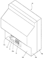
以下、添付図面を参酌しながら、本発明を実施するための最良の形態としての実施例を説明する。なお、実施例1においては、図1は本発明における電子機器であるテレビジョン受像機を背面から見た図である。VTRなどの外部音響機器との接続用のAVジャック端子15、及びアース端子(図示略)などがシャーシの壁面12aに取り付けられて、テレビジョン受像機の後方筐体10bの壁面10cの開口部11から露出するように配置されている斜視図である。このシャーシの壁面12aの一部に本発明の切り欠き部を形成してなる電源コードの固定構造部13aを設けてあり、後方筐体の開口部の縁面により電源コードのブッシュの鍔部が拘束固定されている。
Hereinafter, an embodiment as the best mode for carrying out the present invention will be described with reference to the accompanying drawings. In Example 1, FIG. 1 is a view of a television receiver, which is an electronic apparatus according to the present invention, as seen from the back. An
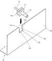
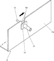
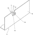
引き続き、順をおって説明を加える。図2は電源コードに設けられたブッシュの構造を示す電源コードの部分拡大斜視図である。電源コード13においてはブッシュ14の厚さ方向の略中央部に周囲に設けられた凹み部分14aを形成している。図3は電源コードの固定構造において電源コードをシャーシの背面側の壁面に固定する前の状態を示す斜視図であり、図4は電源コードの取り付け途中の状態を示す斜視図である。図5はシャーシに設けた電源コードの固定構造に電源コードを固定した状態の斜視図である。図6は電源コードを取り付けて固定した状態のブッシュ断面を示す図である。電子回路基板(図示略)を取り付けるシャーシの壁面12aに配置した略L字型の切り欠き部12bの最深部までブッシュの凹部14aが挿入されている。そして、図3、図4、図5に示す手順に従い、このシャーシ壁面12aの切り欠き部12bに電源コード13のブッシュ14を着脱可能に挿入して固定するようにしており、電子回路基板と電源コードを組み付けたシャーシは略一体に組み立てられたユニットとして取り扱うことが可能であり、組み立て作業の効率化にも寄与できる。また、電源コードが固定された形態で工程間の移動や工場間の輸送が行えることから、物流の際に生じるストレスによる電源コードの切れ及び磨耗を防止する。
Continue to add explanations in order. FIG. 2 is a partially enlarged perspective view of the power cord showing the structure of the bush provided on the power cord. In the
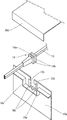
続いて、図8はテレビジョン受像機の完成組み立て工程で、電源コードのブッシュ14がシャーシの壁面12aに固定された状態で筐体壁面10cに組み付けられた相対位置図である。後方筐体10bの開口部11の上縁面11aと脇縁面11bにより、シャーシに形成した切り欠き部12bの開放部12c方向が塞がれてブッシュの抜けを防止し強固に固定している。何らかの事由でシャーシ12や電子回路基板(図示略)を取り外す必要が生じても、後方筐体10bを取り外すだけで筐体の内部のシャーシ壁面12aは露出し、且つ、電源コード13はシャーシ壁面12aの切り欠き部12bに着脱可能に固定された状態を保てる。さらに再度完成品としての組立てを行うにあたっても固定構造部を加工する必要がない。
Next, FIG. 8 is a relative position diagram in which the
さらに、詳細に説明すると、図3はシャーシの壁面12aの上端が開放し、この開放部12cから下向きに切り欠き、さらに横向きに切り込まれた略L字型の切り欠き部12bを形成している。一方の電源コード13においてはブッシュ14の厚さ方向における略中央部の周囲に設けられた凹み部分14aを形成している。シャーシ壁面12aに設けられた切り欠き部12bに上端の開放部12cから、電源コード13のブッシュ14の略中央部の周囲に設けられた凹部14aを挿入してから、図4に示すようにブッシュ14を横方向に移動させて奥に入り込ませる。続いて図5により切り欠き部の最深部に挿入された電源コード13のブッシュ14は、シャーシ壁面12aの上片部12dと切り欠き部の底辺に挟持されてシャーシ壁面12aに固定される。この電源コード13のブッシュ14をシャーシ壁面12aから取り外すときには、逆の手順によってブッシュ14をシャーシ壁面12aの切り欠き部12b内で切り欠きの開放部12c側に移動することによって電源コード13をシャーシ壁面12aから取り外す。
More specifically, in FIG. 3, the upper end of the
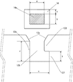
続いて、本実施例において、ブッシュ14がシャーシの切り欠き部12bに挿入された後に、工程間の移動や工場間の輸送中に振動を受けることを想定して固定条件による効果の比較を行った結果を示す。電源コード13のブッシュ14の形状は予め用意されていることが多いため、図7においてはブッシュの凹部14aの横寸法と縦寸法をそれぞれa、及びb、鍔の高さcの既定値とした。一方、シャーシの切り欠き部12bにおけるブッシュとの挿入箇所の寸法は横寸法をx、奥側脇縁面の縦寸法をyとし、該切り欠き部の開口側脇縁面の縦寸法をzとした場合、ブッシュが切り欠き部の最深部に挿入されても容易に移動が可能では固定効果が期待できないため、予め切り欠き部の奥側脇縁面の縦寸法yはブッシュ凹部の縦寸法bとほぼ同等な寸法、すなわちy≒bに設定した。なお、一般的にブッシュ14の成形に用いられるプラスチック類は常温下でも比較的軟質の性状を有したものが用いられており、固定時における抜け防止の安全度を増すには、挿入抵抗が多少増すことになるが切り欠き部の奥側脇縁面の縦寸法yをブッシュ凹部の縦寸法bより僅かに小さ目に調整することで可能である。また、シャーシの開口部深さとブッシュとの関係では、ブッシュが切り欠きの最深部から移動して少し傾いても容易に外れないようにするため、及びブッシュが切り欠きの最深部に固定され、完成品として組み立てられたときにシャーシの開放部が筐体の開口部の縁面の隙間から露出することを防ぐため、シャーシ切り欠き部の開口側脇縁面の縦寸法zと、ブッシュ凹部の縦寸法b及び鍔高さ寸法cとはb+c≦zに設定した。以上の前提に従い、ブッシュ凹部の横寸法aに対してシャーシ切り欠き部の横寸法xの比率を、ブッシュ凹部の横寸法aの1倍から1.5倍まで6段階に分けて組み合わせ、振動の強さを弱、中、強の3段階で負荷をかけて該シャーシ切り欠き部の横寸法xは該ブッシュ凹部の横寸法aの何倍が適当かを比較した。この結果を表1に示す。なお、この表中にあらわした記号は、×:ブッシュの外れあり、△:ブッシュの保持が甘い、○:ブッシュの保持が可能、とした。
Subsequently, in the present embodiment, after the

つづいて図8においては、シャーシの壁面12aに配置した切り欠き状の電源コードの固定構造部13aの位置と、その切り欠き部12bの最深部に挿入されたブッシュ14の位置、及びブッシュ14の外れ防止のために設けた筐体開口部11の上縁面11a、脇縁面11bとの相対位置は予め設定されており、ブッシュがシャーシの切り欠き部の開放部側に移動して外れないように筐体開口部の上縁面11aと脇縁面11bでシャーシ切り欠き部の開放部12c方向、及び切り欠き部の開放側脇縁面12e方向を塞いでブッシュの動きを抑え込むように配置しているが、単に電源コードの抜け防止だけを目的とする場合はシャーシ切り欠き部の開放部12c方向のみを筐体開口部の上縁面11aで塞ぐだけでも目的は達せられる。
Next, in FIG. 8, the position of the fixing
以上のように本実施例では、電源コードの固定構造部をシャーシに設けたことにより、組み立て工程においては簡便に着脱が可能な電源コードの固定ができ、組み立て中における工程間の移動、若しくは工場間の輸送の際に生ずるストレスによる電源コードの切れや磨耗を防ぐことができ、さらには、完成品に組み立てる段階で別途必要となる電子機器の筐体と電源コードの固定手段とそれにかかる作業工数などを不要とする電源コードの固定構造が得られた。 As described above, in this embodiment, the power cord fixing structure portion is provided in the chassis, so that the power cord can be easily attached and detached in the assembly process, and can be moved between processes during assembly, or the factory. In addition, the power cord can be prevented from being cut or worn due to stress generated during transportation, and the electronic equipment casing and power cord fixing means that are required separately during assembly of the finished product and the number of man-hours involved. As a result, a power cord fixing structure that eliminates the need for the above was obtained.
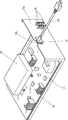
実施例2においては、図9に示す通り電子機器に内蔵されるDVDユニット16を電子回路基板17と共に取り付ける複合電子機器用のシャーシ12の壁面12aに、予め略L字型の切り欠き部12bを形成し、この切り欠き部12bに、電子回路基板17と接続された電源コード13のブッシュ14を着脱可能に挿入して固定することで、工程間の移動、又は工場間の輸送時におけるストレスで受ける電源コードの切れ及び磨耗を防止可能とすることを特徴とする複合電子機器用電源コードの固定構造である。これにより電子回路基板17と内蔵される他の電子機器ユニット、例えばDVDユニット16を、電源コード13の固定構造部13aを有するシャーシ壁面12aに取り付けて略一体化したユニットとして筐体組み付け時に取り扱える。
In the second embodiment, as shown in FIG. 9, a substantially L-shaped
以上、本実施例を詳述したが、本発明は、前記実施例に限定されるものではなく、本発明の要旨の範囲内で種々の変形実施が可能である。例えば、電子機器筐体の開口部側ありで、シャーシに形成した壁面に併設される電源コードの固定構造部、及び各種のジャック端子およびアース端子を設ける側は筐体の背面に限らず、側面に設けることも可能である。また、電源コードを固定するための略L字型の切り欠き部の開口部はシャーシと筐体壁面の配置の都合に合わせて上下左右どちら向きに配置されてもよく、切り欠き部の最深部はブッシュの形状により略円形や略長円などの形状などに変形が可能である。また、シャーシの切り欠き部、及びその周辺は、シャーシの縁面を数ミリの幅で折り曲げてリブを設けるなどにより耐撓み強度を増すなどの改良も可能である。なお本発明における電子機器もテレビジョン受像機のほか、ビデオ、DVD、HDDなどでもよく、さらに該電子機器に内蔵される他の電子機器などの装置類も前記実施例に限定されるものではなく、適宜選定すればよい。 As mentioned above, although the present Example was explained in full detail, this invention is not limited to the said Example, A various deformation | transformation implementation is possible within the range of the summary of this invention. For example, on the side of the opening of the electronic device casing, the side where the power cord fixing structure provided alongside the wall surface formed on the chassis and the various jack terminals and ground terminals are provided is not limited to the rear surface of the casing. It is also possible to provide it. Moreover, the opening of the substantially L-shaped notch for fixing the power cord may be arranged in either the top, bottom, left, or right according to the arrangement of the chassis and the wall surface of the chassis. The deepest part of the notch Depending on the shape of the bush, it can be deformed into a shape such as a substantially circular shape or a substantially oval shape. In addition, the notch portion of the chassis and its periphery can be improved by increasing the bending strength by bending the edge surface of the chassis to a width of several millimeters and providing ribs. Note that the electronic device in the present invention may be a video receiver, a DVD, an HDD, etc. in addition to a television receiver, and devices such as other electronic devices incorporated in the electronic device are not limited to the above embodiments. It may be selected as appropriate.
11 筐体の開口部
11a 開口部の上縁面
11b 開口部の脇縁面
12a シャーシの壁面
12b 切り欠き部
12c 切り欠きの開放部
13 電源コード
13a 電源コードの固定構造部
14 ブッシュ
a ブッシュ凹部横寸法
b ブッシュ凹部縦寸法
c ブッシュの鍔高さ寸法
x 切り欠き部の横寸法
y 切り欠き部の奥側脇縁面の縦寸法
z 切り欠き部の開口側脇縁面の縦寸法
DESCRIPTION OF
Claims (3)
Priority Applications (2)
| Application Number | Priority Date | Filing Date | Title |
|---|---|---|---|
| JP2004103864A JP2005293897A (en) | 2004-03-31 | 2004-03-31 | Electronic apparatus equipped with fixing structure for power cord |
| US11/093,233 US20050217892A1 (en) | 2004-03-31 | 2005-03-30 | Electronic device provided with a power supply cord securement structure |
Applications Claiming Priority (1)
| Application Number | Priority Date | Filing Date | Title |
|---|---|---|---|
| JP2004103864A JP2005293897A (en) | 2004-03-31 | 2004-03-31 | Electronic apparatus equipped with fixing structure for power cord |
Publications (2)
| Publication Number | Publication Date |
|---|---|
| JP2005293897A true JP2005293897A (en) | 2005-10-20 |
| JP2005293897A5 JP2005293897A5 (en) | 2006-12-14 |
Family
ID=35053039
Family Applications (1)
| Application Number | Title | Priority Date | Filing Date |
|---|---|---|---|
| JP2004103864A Pending JP2005293897A (en) | 2004-03-31 | 2004-03-31 | Electronic apparatus equipped with fixing structure for power cord |
Country Status (2)
| Country | Link |
|---|---|
| US (1) | US20050217892A1 (en) |
| JP (1) | JP2005293897A (en) |
Cited By (3)
| Publication number | Priority date | Publication date | Assignee | Title |
|---|---|---|---|---|
| JP2009246769A (en) * | 2008-03-31 | 2009-10-22 | Sharp Corp | Receiver |
| JP2010250221A (en) * | 2009-04-20 | 2010-11-04 | Funai Electric Co Ltd | Thin type display device |
| US7854484B2 (en) | 2007-05-15 | 2010-12-21 | Funai Electric Co., Ltd. | Television receiving set |
Families Citing this family (4)
| Publication number | Priority date | Publication date | Assignee | Title |
|---|---|---|---|---|
| WO2013098042A1 (en) * | 2011-12-30 | 2013-07-04 | Arcelik Anonim Sirketi | A household appliance comprising a cable retainer |
| EP3242540A1 (en) * | 2016-05-06 | 2017-11-08 | Mahle International GmbH | Housing arrangement |
| IT201700074316A1 (en) * | 2017-07-03 | 2019-01-03 | Lef Holding S R L | An electric fruit with an interchangeable front panel |
| CN108917955A (en) * | 2018-08-13 | 2018-11-30 | 郑州泰恩科技有限公司 | A kind of wireless temperature measuring device for switch cabinet |
Family Cites Families (8)
| Publication number | Priority date | Publication date | Assignee | Title |
|---|---|---|---|---|
| US2862996A (en) * | 1956-03-27 | 1958-12-02 | Gen Electric | Strain relief device |
| US3229026A (en) * | 1964-07-30 | 1966-01-11 | Advance Transformer Co | Grommet and canister construction |
| US3510628A (en) * | 1967-02-21 | 1970-05-05 | Federal Pacific Electric Co | Housing having insulating strain relief grommet therethrough |
| US3508291A (en) * | 1968-03-25 | 1970-04-28 | Singer Co | Cord exit device |
| US3920208A (en) * | 1974-02-04 | 1975-11-18 | Leroy D Dowdy | Pipe clamp employing electrolytic corrosion and noise preventive means |
| US4272645A (en) * | 1980-01-29 | 1981-06-09 | The Singer Company | Elastomeric molded strain relief |
| DE3928138A1 (en) * | 1989-08-25 | 1991-02-28 | Audi Ag | BRACKET FOR A PLUG / SOCKET COMBINATION |
| JP3119840B2 (en) * | 1996-11-25 | 2000-12-25 | 日本ケーブル・システム株式会社 | Device for fixing terminals such as control cables |
-
2004
- 2004-03-31 JP JP2004103864A patent/JP2005293897A/en active Pending
-
2005
- 2005-03-30 US US11/093,233 patent/US20050217892A1/en not_active Abandoned
Cited By (3)
| Publication number | Priority date | Publication date | Assignee | Title |
|---|---|---|---|---|
| US7854484B2 (en) | 2007-05-15 | 2010-12-21 | Funai Electric Co., Ltd. | Television receiving set |
| JP2009246769A (en) * | 2008-03-31 | 2009-10-22 | Sharp Corp | Receiver |
| JP2010250221A (en) * | 2009-04-20 | 2010-11-04 | Funai Electric Co Ltd | Thin type display device |
Also Published As
| Publication number | Publication date |
|---|---|
| US20050217892A1 (en) | 2005-10-06 |
Similar Documents
| Publication | Publication Date | Title |
|---|---|---|
| JPH11277582A (en) | Method and apparatus for molding electromagnetic shielding housing | |
| CN101578752A (en) | Motor control device | |
| JP2005293897A (en) | Electronic apparatus equipped with fixing structure for power cord | |
| US5419629A (en) | Electronics chassis and method of manufacture therefor | |
| JP2005293897A5 (en) | ||
| EP3768051B1 (en) | Housing for electronic component | |
| US8229520B2 (en) | Cover part for electronic equipment and electronic equipment having the same | |
| US8971027B2 (en) | Display device cabinet | |
| US20130323094A1 (en) | Fan motor | |
| JP2005318770A (en) | Power converter | |
| US7321286B2 (en) | Electrical junction box | |
| KR20180010934A (en) | Connector assembly having protect plate | |
| JP2009278800A (en) | On-vehicle electric connection box | |
| JP2005136154A (en) | Circuit board storage structure and electrical junction box | |
| US7262970B2 (en) | Electronic device | |
| CN119678664A (en) | Integrated fastening structure and electronic device including the same | |
| JP7587016B2 (en) | How to assemble electronic devices | |
| US20250211055A1 (en) | Pump Comprising a Motor Housing and an Electronics Housing Detachably Mounted on the Motor Housing | |
| JP4934332B2 (en) | Electrical junction box | |
| CN205398926U (en) | Integrated sewing machine electric control device | |
| JP5157824B2 (en) | Electrical junction box and method of assembling the electrical junction box | |
| JP6465336B2 (en) | solenoid | |
| US20250062063A1 (en) | Inductor thermal management system | |
| JPH06325943A (en) | Coil transformer | |
| JP3249657B2 (en) | Insulated mounting frame |
Legal Events
| Date | Code | Title | Description |
|---|---|---|---|
| A521 | Request for written amendment filed |
Free format text: JAPANESE INTERMEDIATE CODE: A523 Effective date: 20061026 |
|
| A621 | Written request for application examination |
Free format text: JAPANESE INTERMEDIATE CODE: A621 Effective date: 20061026 |
|
| A977 | Report on retrieval |
Free format text: JAPANESE INTERMEDIATE CODE: A971007 Effective date: 20081017 |
|
| A131 | Notification of reasons for refusal |
Free format text: JAPANESE INTERMEDIATE CODE: A131 Effective date: 20081028 |
|
| A02 | Decision of refusal |
Free format text: JAPANESE INTERMEDIATE CODE: A02 Effective date: 20090310 |