JP2005293811A - Hard disk device fixture and electronic device - Google Patents
Hard disk device fixture and electronic device Download PDFInfo
- Publication number
- JP2005293811A JP2005293811A JP2004111710A JP2004111710A JP2005293811A JP 2005293811 A JP2005293811 A JP 2005293811A JP 2004111710 A JP2004111710 A JP 2004111710A JP 2004111710 A JP2004111710 A JP 2004111710A JP 2005293811 A JP2005293811 A JP 2005293811A
- Authority
- JP
- Japan
- Prior art keywords
- hard disk
- housing
- fixture
- frame body
- mounting
- Prior art date
- Legal status (The legal status is an assumption and is not a legal conclusion. Google has not performed a legal analysis and makes no representation as to the accuracy of the status listed.)
- Pending
Links
Images
Landscapes
- Casings For Electric Apparatus (AREA)
Abstract
【課題】 筐体に対するハードディスク装置の着脱を容易に行えるようにしたハードディスク装置の取付具及び電子機器を提供すること。
【解決手段】 ハードディスク装置の取付具120は、複数のハードディスク装置140を収容可能な枠体121と、この枠体121の外壁部に設けられ、筐体143のハードディスク装置取付壁部172に設けられた被掛止部168に着脱自在に掛止される掛止部139aとを備える。
【選択図】 図8PROBLEM TO BE SOLVED: To provide a mounting device for a hard disk device and an electronic device which can be easily attached to and detached from a housing.
A hard disk device fixture 120 is provided on a frame body 121 that can accommodate a plurality of hard disk devices 140, an outer wall portion of the frame body 121, and a hard disk device mounting wall portion 172 of a housing 143. And a latching portion 139a that is detachably latched on the latched portion 168.
[Selection] Figure 8
Description
本発明は、電子機器筐体の内部に内蔵されるハードディスク装置をその筐体に取り付けるためのハードディスク装置の取付具及び電子機器に関し、詳しくは、着脱を容易に行えるようにしたハードディスク装置の取付具及び電子機器に関する。 BACKGROUND OF THE INVENTION 1. Field of the Invention The present invention relates to a hard disk device mounting tool and an electronic device for mounting a hard disk device built in an electronic device housing to the housing, and more particularly to a hard disk device mounting device that can be easily attached and detached. And electronic devices.
従来、テレビ番組の録画や、ビデオカメラで撮影した映像の保存などはビデオカセットテープに行うのが一般的であったが、最近では編集のしやすさやビデオカセットテープの交換なしに長時間記録を行えるなどの点から、パーソナルコンピュータやハードディスクレコーダに備えられるハードディスク装置に記録を行うことが急速に普及している。 Conventionally, recording of TV programs and storage of video taken with a video camera was generally performed on a videocassette tape, but recently it has been recorded for a long time without the need for editing and replacement of the videocassette tape. From the standpoint of being able to perform recording, it is rapidly spreading to perform recording on a hard disk device provided in a personal computer or a hard disk recorder.
その場合に、テレビ番組などの動画データはデータ量が大きいため、パーソナルコンピュータやハードディスクレコーダに備えられるハードディスク装置の容量も大容量にする必要があり、複数台のハードディスク装置を備えるものが増えてきている。例えば特許文献1に示される電子機器では8台のハードディスク装置を筐体内に備えている。
また、例えばタワー型のパーソナルコンピュータにあっては、最初から複数台のハードディスク装置が備えられていなくても、使用者の必要に応じて後からハードディスク装置を増設できるように筐体内にその取り付けのためのスペースが確保されているものも多い。 In addition, for example, in a tower type personal computer, even if a plurality of hard disk devices are not provided from the beginning, the hard disk devices can be installed in the chassis so that the hard disk devices can be added later as required by the user. Many have enough space for them.
従来、ハードディスク装置は取付具に固定され、その取付具が筐体にねじ止めされることで筐体に対して取り付けられる。このようにねじ止めにて固定されるため、生産工程におけるハードディスク装置の取り付け、あるいは修理のために交換する場合や、増設する場合の着脱に際して手間がかかり、特に複数台のハードディスク装置を備えるものではハードディスク装置が複数台ある分、非常に取り扱いにくかった。 Conventionally, a hard disk device is fixed to a fixture, and the fixture is attached to the casing by being screwed to the casing. Since it is fixed by screwing in this way, it takes time to attach or detach the hard disk device during the production process, or to replace it for repair, or when adding it, especially when it has multiple hard disk devices Because there are multiple hard disk devices, it was very difficult to handle.
本発明は上述の問題に鑑みてなされ、その目的とするところは、筐体に対するハードディスク装置の着脱を容易に行えるようにしたハードディスク装置の取付具及び電子機器を提供することにある。 The present invention has been made in view of the above problems, and an object of the present invention is to provide a mounting device for a hard disk device and an electronic apparatus that can be easily attached to and detached from the housing.
本発明のハードディスク装置の取付具は、ハードディスク装置を収容可能な枠体と、この枠体の外壁部に設けられ、電子機器筐体のハードディスク装置取付壁部に着脱自在に掛止される掛止部とを備えることを特徴としている。 The hard disk device fixture of the present invention includes a frame that can accommodate the hard disk device, and a latch that is provided on the outer wall of the frame and is detachably latched on the hard disk device mounting wall of the electronic device housing. It is characterized by providing a part.
上記枠体の内部にハードディスク装置を収容したうえで、その取付具を筐体に引っ掛けるので、ねじを用いて取り付ける場合に比べ、着脱を簡単に行える。特に、複数台のハードディスク装置を取り付ける場合には、枠体の内部にそれら複数のハードディスク装置を収容することで、それら複数のハードディスク装置及び取付具を1つのユニットとして取り扱うことができ、作業者の負担を軽減できる。 Since the hard disk device is accommodated in the frame and the mounting tool is hooked on the housing, it can be easily attached and detached as compared with the case of using a screw. In particular, when mounting a plurality of hard disk devices, the plurality of hard disk devices and fixtures can be handled as a single unit by accommodating the plurality of hard disk devices inside the frame. The burden can be reduced.
また、上記枠体に対して回動自在に連結されたレバー部材と、そのレバー部材の端縁部に設けられ、筐体に形成された係合部に係合されることで、筐体に対する枠体の掛止が解除される方向への枠体の移動を規制するロック部とを備える構成とすれば、取付具の筐体に対する掛止を解除しようとする力が働いてもロック部が係合部に係合することで、取付具の掛止解除方向への移動が規制される。これにより、筐体に対する取付具の安定した掛止状態を保持できる。 Further, a lever member that is rotatably connected to the frame body, and an end portion of the lever member, and is engaged with an engaging portion formed on the housing, thereby being attached to the housing. And a lock portion that restricts the movement of the frame body in the direction in which the frame body is unlocked. By engaging with the engaging portion, the movement of the fixture in the latch release direction is restricted. Thereby, the stable latching state of the fixture with respect to a housing | casing can be hold | maintained.
また、上記レバー部材に一体に設けられ、上記ロック部が上記係合部との係合から解除された状態で、上記枠体の外壁部から離間される取手部を備える構成とすれば、その取手部によって取付具が持ちやすくなり、ハードディスク装置の台数が多い場合や、取り付けにくい箇所であって容易に着脱を行える。また、取手部を持つために枠体の外壁部から離間させる動作がそのままロック部の係合部からの解除動作となっているため、取り外し方法がわかりやすく、作業者の手間もかからない。 Further, if the lever member is integrally provided, and the lock portion is released from the engagement with the engagement portion, the handle member is separated from the outer wall portion of the frame body. The handle portion makes it easy to hold the fixture, and can be easily attached and detached when the number of hard disk devices is large or when it is difficult to attach. In addition, since the operation of separating the frame from the outer wall portion to have the handle portion is the releasing operation from the engaging portion of the lock portion as it is, the removal method is easy to understand and does not require the labor of the operator.
また、枠体の内部に、複数のハードディスク装置を互いに離間させて支持可能なハードディスク支持部を備えさせれば、各ハードディスク装置間に空気の通る間隙を確保でき、ハードディスク装置が発する熱の放熱性を高めることができる。 In addition, if a hard disk support portion that can support a plurality of hard disk devices separated from each other is provided inside the frame body, a space for air to pass between the hard disk devices can be secured, and heat dissipation of the heat generated by the hard disk device can be secured. Can be increased.
本発明の電子機器は、筐体と、この筐体の内部に内蔵されるハードディスク装置を筐体に取り付けるための取付具とを備え、
筐体は、ハードディスク装置の取付壁部に設けられた被掛止部を備え、
取付具は、ハードディスク装置を収容可能な枠体と、この枠体の外壁部に設けられ、筐体の被掛止部に着脱自在に掛止される掛止部とを備えることを特徴としている。
An electronic apparatus of the present invention includes a housing and a fixture for attaching the hard disk device built in the housing to the housing,
The housing includes a hooked portion provided on the mounting wall of the hard disk device,
The fixture includes a frame that can accommodate the hard disk device, and a hooking portion that is provided on the outer wall of the frame and is detachably hooked to the hooked portion of the housing. .
上記枠体の内部にハードディスク装置を収容したうえで、その取付具の掛止部を筐体の被掛止部に引っ掛けるので、ねじを用いて取り付ける場合に比べ、着脱を簡単に行える。特に、複数台のハードディスク装置を取り付ける場合には、枠体の内部にそれら複数のハードディスク装置を収容することで、それら複数のハードディスク装置及び取付具を1つのユニットとして取り扱うことができ、作業者の負担を軽減できる。 Since the hard disk device is accommodated in the frame and the hooking portion of the fixture is hooked on the hooking portion of the housing, the attachment and detachment can be easily performed as compared with the case of using a screw. In particular, when mounting a plurality of hard disk devices, the plurality of hard disk devices and fixtures can be handled as a single unit by accommodating the plurality of hard disk devices inside the frame. The burden can be reduced.
また、筐体の取付壁部との間で枠体を挟み込むように筐体に固定される補助取付具を備えた構成とすれば、取付具は取付壁部と補助取付具の2面で挟み込まれ、2方向から面で押さえられており振動や衝撃に強いため、取付強度を高めることができる。 Moreover, if it is set as the structure provided with the auxiliary | assistant fixture fixed to a housing | casing so that a frame may be pinched | interposed between the attachment wall part of a housing | casing, a fixture will be pinched | interposed by two surfaces, an attachment wall part and an auxiliary | assistant fixture. Since it is pressed by the surface from two directions and is strong against vibration and impact, the mounting strength can be increased.
また、上記補助取付具は、筐体内に内蔵される他の機器の収容凹部を備える構成とすれば、その収容凹部内に例えば光ディスク装置などの他の機器を配置できるため電子機器に具備される内蔵機器や部品の配置レイアウトの自由度が増す。 In addition, if the auxiliary fixture is configured to include a housing recess for another device built in the housing, other devices such as an optical disk device can be disposed in the housing recess, so that the auxiliary fixture is included in the electronic device. The degree of freedom in the layout of internal devices and parts is increased.
さらに、上記補助取付具が、上記ロック部の上記係合部からの解除を規制するように上記レバー部材を押さえ込むようにすれば、振動等でロック部が係合位置(ロック位置)から外れることを防げる。さらに、補助取付具がロック部をロック位置へと押さえる構造であるため、ロックし忘れた状態であっても補助取付具を取り付ければ自然にロック部が係合部に係合される。これにより、ロックのし忘れによる脱落などを防ぐことができる。 Furthermore, if the auxiliary fixture presses the lever member so as to restrict the release of the lock portion from the engagement portion, the lock portion is released from the engagement position (lock position) due to vibration or the like. Can be prevented. Furthermore, since the auxiliary attachment has a structure that presses the lock portion to the lock position, even if the auxiliary attachment is attached, the lock portion is naturally engaged with the engagement portion even when the auxiliary attachment is attached. As a result, it is possible to prevent dropping due to forgetting to lock.
本発明のハードディスク装置の取付具によれば、枠体の内部にハードディスク装置を収容したうえで、その枠体の外壁部に設けられた掛止部を筐体に引っ掛けるので着脱を簡単に行え、筐体に対するハードディスク装置着脱の手間を軽減できる。 According to the mounting device of the hard disk device of the present invention, after the hard disk device is accommodated inside the frame body, the hooking portion provided on the outer wall portion of the frame body is hooked on the housing, so that it can be easily attached and detached. The trouble of attaching / detaching the hard disk device to / from the housing can be reduced.
本発明の電子機器によれば、枠体の内部にハードディスク装置を収容したうえで、その枠体の外壁部に設けられた掛止部を筐体に引っ掛けるので着脱を簡単に行え、筐体に対するハードディスク装置着脱の手間を軽減できる。この結果、電子機器生産効率の向上が図れる。 According to the electronic apparatus of the present invention, the hard disk device is accommodated in the frame body, and the hook portion provided on the outer wall portion of the frame body is hooked on the housing, so that the attachment / detachment can be easily performed. The trouble of attaching / detaching the hard disk device can be reduced. As a result, the production efficiency of electronic equipment can be improved.
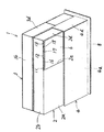
図1は本発明の実施形態に係る電子機器1の外観斜視図を示す。図2、図3はそれぞれ、電子機器1の正面図、上面図である。本実施形態では、電子機器1は、いわゆるタワー型パーソナルコンピュータの本体である。 FIG. 1 is an external perspective view of an electronic apparatus 1 according to an embodiment of the present invention. 2 and 3 are a front view and a top view of the electronic apparatus 1, respectively. In this embodiment, the electronic device 1 is a main body of a so-called tower type personal computer.
電子機器1は、筐体2及び3が組み合わされなる直方体形状の外部筐体を有し、その外部筐体は台座8によって設置面上に支持される。
The electronic device 1 has a rectangular parallelepiped outer casing in which the
筐体2は、前板部2aと、前板部2aの縁部を囲むように設けられた上板部2b、側板部2c、2dとからなる箱型形状を呈している。前板部2aには四角形状の開口2eが形成されている。開口2eは、前板部2aの上半分ほどの領域であって側板部2d寄りの箇所に形成されている。また、前板部2aには、開口2eを開閉するためのシャッター6が設けられている。
The
開口2eの上縁部の近傍であって、上板部2bと前板部2aとの角部には、各種押しボタン11、12、13が配設されている。押しボタン11と12との間にはスペーサ16が、押しボタン12と13との間にはスペーサ17が設けられている。これらスペーサ16、17は押されても筐体内部に押し込まれず、押しボタンとしては機能しない。スペーサ17には発光窓部18が設けられている。
筐体2において下半分ほどの部分には板状の外装部材4が取り付けられている。外装部材4は、筐体2の前板部2aの下半分を覆う前板部4aと、筐体2の側板部2dの下方の領域を覆う側板部4dとからなる。
A plate-shaped
筐体3は、背板部3aと、背板部3aの縁部を囲むように設けられた上板部3b、側板部3c、3dとからなる箱型形状を呈している。
The
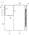
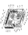
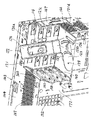
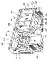
上述した外部筐体は例えば樹脂材料からなり、その内部には、図5に示す内部筐体143が内蔵されている。内部筐体143は、例えば金属材料からなり、電子機器1の剛性を高める補強部材及び内蔵機器の取付部材として機能する。
The above-described external housing is made of, for example, a resin material, and an
内部筐体143は、後述するハードディスクの取付壁部172と、この取付壁部172の縁部を囲むように設けられた上板部144と、側板部145、148、147と、底板部146とからなる箱型形状を呈している。
The
上板部144には吸気用開口167が多数の小孔として形成されている。側板部145には吸気用開口151が多数の小孔として形成されている。側板部147には吸気用開口166、162が多数の小孔として形成されている。
In the
側板部148には排気用開口153、154が多数の小孔として形成されている。さらに、側板部148には、配線接続部である各種コネクタを露出させるための開口43、44、149が形成されている。
底板部146には吸気用開口155が多数の小孔として形成されている。また、底板部146には、吸気と内部筐体143の軽量化を図るための開口159、160、161が形成されている。さらに、底板部146には、内部筐体143内に配設されたチューナーの入力端子を露出させるための開口156、157、158が形成されている。
The
取付壁部172には、吸気と内部筐体143の軽量化を図るための開口152、165、164、163が形成されている。また、取付壁部172において、開口165が形成された領域は内部筐体143内に収容される内蔵機器であるハードディスク装置の取付領域であり、その領域には、複数のハードディスク装置を収容した後述する枠体が引っ掛けられるようにして着脱自在に取り付けられる4つの掛止部168が、取付壁部172の内面側に突出して設けられている。さらに、そのハードディスク装置取付領域の上部には、横長の係合孔169が形成されている。
内部筐体143の内部には、ハードディスク装置の他にも、マザーボード、チューナーボード、電源ユニットなどの各種内蔵機器が配設される。
In addition to the hard disk device, various internal devices such as a motherboard, a tuner board, and a power supply unit are disposed inside the
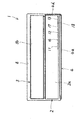
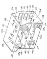
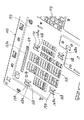
図6に、本実施形態に係るハードディスク装置の取付具120の斜視図を示す。取付具120は、枠体121とレバー部材122とからなる。枠体121及びレバー部材122は共に金属材料からなる。図7は、枠体121のみを図6とは別角度から見た斜視図である。
FIG. 6 is a perspective view of the mounting
枠体121は4つの側板部121a、121b、121c、121dからなり、これら側板部121a、121b、121c、121dによって囲まれた枠体121の内部は、ハードディスク装置の収容部となっている。
The
側板部121aには、図7に示すように、膨出部135と、ストッパ部127と、ガイド部126が設けられている。膨出部135の中心には貫通孔が形成されている。ストッパ部127及びガイド部126は何れも側板部121aに切れ込みを入れて形成された片を側板部121a表面側に突出させるように立ち上げて設けられている。ガイド部126はさらにL字状に屈曲されている。
As shown in FIG. 7, the
側板部121aに平行に対向している側板部121dにも、側板部121aと同様な膨出部135、ストッパ部127、ガイド部126が設けられている。
The
側板部121a及び側板部121dに垂直な側板部121cには、図6に示されるように、膨出部132、133、ハードディスク支持部131、ハードディスク固定部130が設けられている。膨出部132、133のそれぞれの中心にはねじ孔が形成されている。ハードディスク固定部130は複数設けられ、各々は、側板部121cに切れ込みを入れて形成されその側板部121cに片持ち支持された片である。各々のハードディスク固定部130には貫通孔が形成されている。ハードディスク支持部131は複数設けられ、各々は、側板部121cに切れ込みを入れて形成された片を枠体121の内部に屈曲させて突出させてなる。各々のハードディスク支持部131は、側板部121cに対してほぼ直角に屈曲されている。
As shown in FIG. 6, the
側板部121cに平行に対向している側板部121bには、図7に示されるように、側板部121bの外壁側に膨出している膨出部138と、ハードディスク支持部131と、多数の丸孔状の貫通孔142が設けられている。膨出部138は、側板部121bの四隅近傍に設けられ、各膨出部138には掛止孔139が形成されている。
As shown in FIG. 7, the
各掛止孔139は、側板部121bの内壁部と外壁部とを貫通するボトル形状の貫通孔として形成されており、その掛止孔139における幅広部分と幅狭部分との間の段部は、後述する筐体に設けられた被掛止部に引っ掛けられる掛止部139aとして機能する。
Each retaining
ハードディスク支持部131は、上記側板部121cに設けられたものと同様、側板部121bに切れ込みを入れて形成された片を枠体121の内部に屈曲させて突出させてなる。各々のハードディスク支持部131は、側板部121bに対してほぼ直角に屈曲されている。
The hard
レバー122部材は、側板部121a及び121dに対して回動自在に取り付けられる1対の回動板部123と、その1対の回動板部123を連結する取手部116とからなる。
The
回動板部123は、軸部材128を中心に、側板部121a(121d)に対して回動可能となっている。軸部材128は、側板部121a(121d)の膨出部135に形成された貫通孔に嵌合される。また、回動板部123には、2本の細長いくぼみ134が形成されて剛性が高められ、たわみにくくされている。
The
側板部121aに取り付けられた回動板部123の直線状の端縁部はロック部123として機能し、取付具120が図5に示す内部筐体143に取り付けられるとその筐体に形成された係合孔169に差し込まれる。
The linear end edge portion of the
取手部116は、側板部121aに平行な略正方形状の側板部125bと、側板部121dに平行な略正方形状の側板部125aと、これら側板部125a、125b間を連結する矩形板部124とからなる。側板部125a、125bのそれぞれの一縁部は回動板部123に一体に結合され、その一縁部に対向する縁部に矩形板部124が一体に結合されている。矩形板部124にはくり抜き孔124aが形成されている。
The
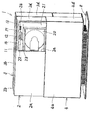
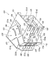
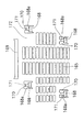
上記枠体121の内部には、図8に示すように複数個(例えば4個)のハードディスク装置140が収容される。各々のハードディスク装置140は、枠体121の内部に突出された4つのハードディスク支持部131に支持される。なお、最下段のハードディスク装置140は、枠体121の側板部121d内面に設けられた4つのハードディスク支持部137(図7参照)に支持される。
A plurality of (for example, four)
各々のハードディスク装置140において2つある長尺側端面のうち、枠体121の側板部121c内面に対向される端面は、側板部121cに設けられたハードディスク固定部130に固定される。具体的には、各ハードディスク固定部130にあけられた丸孔状の貫通孔に図8に示すねじ141が通されて、そのねじ141が各ハードディスク装置140の上記端面に螺着される。各端面の長尺方向に沿った両端部寄りの2箇所にねじ止めされる。これによって、各ハードディスク装置140は枠体121に対して固定される。
Of the two long side end surfaces in each
また、上記ねじ止めの際に、ハードディスク固定部130が側板部121cに対して揺動可能に片持ち支持されていることから、すなわち各ハードディスク装置140の端面に近づく方向とその反対に遠ざかる方向とに揺動可能であるので、ハードディスク装置140の短尺側の幅の違いに対して柔軟に対応できる。
In addition, since the hard
図8において、最上段のハードディスク装置140の上面と枠体121の側板部121a内面との間には間隙が形成され、その最上段のハードディスク装置140の下面と2段目のハードディスク装置140の上面との間にも間隙が形成され、2段目のハードディスク装置140の下面と3段目のハードディスク装置140の上面との間にも間隙が形成され、3段目のハードディスク装置140の下面と最下段のハードディスク装置140の上面との間にも間隙が形成されている。さらに、最下段のハードディスク装置140は、側板部121dの内面に突出して設けられた4つのハードディスク支持部137(図7にその1つのみを図示)に支持されるので、最下段のハードディスク装置140の下面と側板部121dの内面との間にも間隙が形成される。
In FIG. 8, a gap is formed between the upper surface of the uppermost
以上のように、各ハードディスク装置140は互いに離間された状態で(互いに接触せずに)重ねられ、また側板部121a、121dにそれぞれ向き合わされるハードディスク装置140もそれら側板部121a、121dとの間に間隙を形成しているので、ハードディスク装置140が発する熱の放熱性を高めることができる。
As described above, the
また、枠体121の各側板部には多数の開口が形成され、さらに枠体121は4つの側板部からなる角筒状を呈しているので、枠体121の内部は通気性に優れ、その内部にハードディスク装置140の熱がこもることを防いで放熱性を高めることができる。
In addition, a large number of openings are formed in each side plate portion of the
図9は、上述した内部筐体143の取付壁部172の要部拡大図を示す。取付壁部172において被掛止部168形成箇所には、被掛止部168及びガイド部171を残すようにしてくり抜き孔170が形成されている。被掛止部168の下端部は取付壁部172に一体に結合され、被掛止部168の上端部中央はガイド部171の下端部と一体に結合され、ガイド部171の上端部は取付壁部172に一体に結合されている。被掛止部168及びガイド部171は、内部筐体143の内部に向けて(図9において紙面手前側に向けて)湾曲されて突出している。ガイド部171の幅は被掛止部168の幅よりも小さく、被掛止部168とガイド部171との間には段部168aが形成されている。
FIG. 9 is an enlarged view of a main part of the mounting
以上のように構成される取付具120は、以下のようにして内部筐体143の取付壁部172に取り付けられる。
The
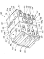
複数のハードディスク装置140を枠体121の内部に収容した取付具120は、図10に示すように、枠体121の側板部121bを内部筐体143の取付壁部172に対向させ、側板部121aを内部筐体143の上板部144に対向させた姿勢でもって取付壁部172に取り付けられる。
As shown in FIG. 10, the
具体的には、枠体121の側板部121bに設けられた掛止孔139の段部である掛止部139a(図7参照)を、取付壁部172に設けられた被掛止部168の段部168a(図9参照)に引っ掛ける。これによって、取付具120は、取付壁部172に設けられた被掛止部168の段部168aにぶら下がるようにして支持される。
Specifically, a hooking
上記取り付けの際に、掛止孔139の上部である細い矩形状の部分を、被掛止部168の上端部側に設けられたガイド部171に挿入してそのまま取付具120を下方に移動させると、掛止部139aが、被掛止部168の段部168aに引っ掛かる位置に移動され、容易に両者の掛止を行える。
At the time of the above attachment, the thin rectangular portion that is the upper portion of the hooking
また、取付壁部172から突出している被掛止部168及びガイド部171は、掛止孔139を介して側板部121bの内方に入り込むが、掛止孔139は、側板部121bの外壁部に膨出された膨出部138に形成されているので、上記被掛止部168及びガイド部171はその膨出部138内にとどまって枠体121内部のハードディスク装置140に突き当たることがない。
Further, the hooked
上述のようにして、取付具120を取付壁部172に掛止した後、レバー部材122を、図10に示す位置から、図11に示す位置へと移動させる。具体的には、図10の状態で枠体121から離間されている取手部116を側板部121cに押し付けるように倒して、軸部材128を支点に回動板部123を回動させる。
As described above, after the
これにより、レバー部材122の回動板部123が側板部121aの外壁上を軸部材128を支点に回動して、回動板部123の直線状の端縁部であるロック部123a(図6、8参照)が、取付壁部172に形成された細長い係合孔169(図5、9参照)に差し込まれる。図12は、取付具120が取付壁部172に掛止され、かつロック部123aが係合孔169に差し込まれた状態における、取付壁部172を外壁面側から見た斜視図である。係合孔169に差し込まれたロック部123aは、その先端部が係合孔169から取付壁部172の外壁面側にわずかに突き出る。
As a result, the
取付壁部172に掛止された取付具120が上方に移動すると、掛止部139aと被掛止部168との掛止が外れるが、上述したようにロック部123aが係合孔169に差し込まれることで、取付具120を上方へ移動させようとする力が働いてもロック部123aが係合孔169の内縁部に引っかかることで、取付具120の上方への移動が規制される。これにより、筐体143に対する取付具120の安定した掛止状態を保持できる。
When the
なお、係合孔169は取付壁部172の上部側にだけ形成されて下部側には形成されていないので、図10において枠体121の下面となる側板部121dの外壁部上を回動される回動板部123の端縁部123bはロック部としては機能せず、取付壁部172に対して隙間をあけて対向される、あるいは負荷を与えない程度で接触される。もちろん、取付壁部172の下部側にも係合孔を形成して、上記端縁部123bをその係合孔に差し込まれるロック部として機能させてもよい。
Since the
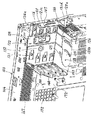
内部筐体143において、外部筐体2の前板部2aと向き合わされる部分には図13に示すように補助取付具94が取り付けられる。
As shown in FIG. 13, an
補助取付具94は剛性の高い金属材料からなり、光ディスク装置の本体が収容される収容凹部96と、その光ディスク装置の本体から引き出されたディスクトレーが収容される凹所21を有する。
The
収容凹部96の上方にはフック部103が設けられており、そのフック部103は、内部筐体143の上板部144と、その上板部144の前端縁部と略直角になるように設けられた帯板部144aとの角部に引っ掛けられる。
A
収容凹部96の左端縁部にはフランジ部101が設けられており、そのフランジ部101は、内部筐体143の側板部145の前端縁部と略直角になるように設けられた帯板部に例えばねじ止めされる。
A
凹所21の右端縁部にはフランジ部102が設けられており、そのフランジ部102は、内部筐体143の側板部147の前端縁部と略直角になるように設けられた帯板部に例えばねじ止めされる。
A
以上のようにして、補助取付具94は内部筐体143に対して固定されるが、さらにハードディスク装置の取付具120にも固定される。
As described above, the
凹所21は、その底部外面が、上記取付壁部172に取り付けられた取付具120の枠体121の側板部121c及び取手部116の矩形板部124に押し当てられる。そして、その凹所21の中央には2つの貫通孔98が形成されており、その貫通孔98にねじが通されて、これらねじはそれぞれ側板部121cに設けられた膨出部132、133に形成されたねじ孔に螺着される。図11に示すように、膨出部133は取手部116の矩形板部124に形成されたくり抜き孔124aから露出している。以上のことにより、取付具120は、筐体143の取付壁部172と補助取付具94との間に挟まれるようにして両者に対して固定される。
The bottom surface of the
内部筐体143において補助取付具94が取り付けられた側には上述した外部筐体2が被せられる。そして、外部筐体2の上板部2bと前板部2aとの角部に配置された押しボタン11を押すと、上記収容凹部96に収容された光ディスク装置の本体からディスクトレーが凹所21へと引き出され、外部筐体2の前板部2aに設けられたシャッター6がそのディスクトレーの動作に連動して自動で下方にスライド移動され、図4に示すように、凹所21及びそこに引き出されたディスクトレー20が前板部2aの開口2eから露出され、ディスクトレー20に対するディスク状記録媒体の着脱が行える。
The
なお、凹所21の上方には、図4に示すように、各種半導体メモリカードのスロット22、23、24が設けられ、シャッター6が開くとそれらスロット22、23、24に対する半導体メモリカードの挿脱も行える。
As shown in FIG. 4,
上記押しボタン11を再び押して、ディスクトレー20が光ディスク装置の本体に装填されるとそれに連動してシャッター6も自動で閉まる。なお、押しボタン12を押すことで、ディスクトレー20の動作に関係なく、シャッター6の上下動(開閉動作)を行わせることができる。
When the
複数のハードディスク装置140は上述したように取付具120を用いて1つのユニットとして内部筐体143に取り付けられるが、例えば4つのハードディスク装置140のうち少なくとも1つもより大容量のものに交換したい、あるいは初め枠体121には3つ以下のハードディスク装置140しか収容しておらず、その後追加したいといった場合には、取付具120ごと内部筐体143から取り外す。その取り外しに際しては、取付具120は内部筐体143に引っ掛けてあるだけなので簡単に取り外すことができる。
As described above, the plurality of
具体的には、例えば図11の状態にある取手部116を手前に引いて、上述した係合孔169からロック部123aを抜く。これによって、取付具120の上方への移動が可能になるので、取付具120を上方へとスライド移動させて、上述した被掛止部168に対する掛止部139aの引っ掛かりを外す。これによって複数のハードディスク装置140をまとめて取付具120ごと内部筐体143から取り外すことができる。
Specifically, for example, the
そして、図11のロック状態から取手部116を手前に引くと、図10に示すように取手部116は枠体121から離間され、取手部116の矩形板部124に形成されたくり抜き孔124aに手を掛けて持つことができる。
Then, when the
側板部121a、121dの外壁部上にそれぞれ設けられたガイド部126は、回動板部123の縁部に非接触で被さるようにされており、回動板部123の、側板部121a、121d上からの浮き上がりを防止する。
The
以上述べたように、本実施形態では、複数のハードディスク装置をまとめて1つの取付具120に収容したうえで、その取付具120を筐体143に引っ掛けるので、従来のように各ハードディスク装置をそれぞれ取付具を用いて筐体に対してねじ止めする場合に比べ、着脱を簡単に行える。また、筐体の底部あるいはベイと呼ばれる箱状の収容部以外の箇所にも取り付けることができるので、配置レイアウトの自由度も高い。
As described above, in the present embodiment, a plurality of hard disk devices are collectively accommodated in one
また、取付具120の持ち運び用の取手部116を引き出す動作がそのままロック部123aの係合孔169からの解除動作となっているため、取り外し方法がわかりやすく、作業者の手間もかからない。
In addition, since the operation of pulling out the carrying
その取手部116によって取付具120が持ちやすくなっているため、ハードディスク装置140の台数が多い場合や(上記説明では4台としたがこれより多くてもあるいは少なくてもよい)、取り付けにくい箇所であって容易に着脱を行える。さらに、取手部116とロック部123aとを一体の一部材であるレバー部材122によって実現しているため部品点数を減らしコストダウンが図れる。
Because the
また、ロック部123aをロック位置(係合孔123aに差し込まれた位置)に押さえ込みつつ取付具120自体も押さえ込むように補助取付具94が筐体143に取り付けられるため、振動等でロック部123aがロック位置から外れることを防げると共に、取付具120は取付壁部172と補助取付具94の2面で挟み込まれ、2方向から面で押さえられており振動や衝撃に強いため、底面に支えがない箇所にも十分な取付強度でもって取り付けることができる。これにより、取付箇所や取付姿勢を選ばない。
In addition, since the
補助取付具94がロック部123aをロック位置へと押さえる構造であるため、図10に示すロックし忘れた状態であっても補助取付具94を取り付ければ自然にロック部123aが係合孔169に差し込まれるようになっており、ロックのし忘れによる脱落などを防ぐことができる。
Since the
また、補助取付具94は、内部筐体143の側板部145と側板部147との間に梁のようにわたされて取り付けられているので、内部筐体143及び電子機器1全体の剛性を高めることにも寄与している。
In addition, since the
さらに、補助取付具94に設けられた凹部96内に光ディスク装置を配置できるため内蔵機器や部品配置レイアウトの自由度が増す。
Furthermore, since the optical disk device can be arranged in the
以上、本発明の実施形態について説明したが、勿論、本発明はこれに限定されることなく、本発明の技術的思想に基づいて種々の変形が可能である。 As mentioned above, although embodiment of this invention was described, of course, this invention is not limited to this, A various deformation | transformation is possible based on the technical idea of this invention.
上記実施形態では、取付具120を、内部筐体143の背板部に相当する壁部172に取り付けたが、これに限らず、上板部144、側板部145、148、147、底板部146に引っ掛けて取り付けてもよい。
In the above embodiment, the
また、被掛止部を上記壁部172の内面側に突出した突起として設け、レバー部材122に設けられる掛止部をその突起状の被掛止部に係合する係合孔としてもよい。
Alternatively, the hooked portion may be provided as a protrusion protruding on the inner surface side of the
また、レバー部材122は軸部材128を支点に回動される構成ではなく、取付具120が取り付けられる壁部172に対して直線軌跡でもって近づいたり遠ざかったりする往復移動される構成としてもよい。
In addition, the
上記実施形態では、電子機器をタワー型コンピュータの本体として説明したが、例えばハードディスクレコーダ、DVD(Digital Versatile disc)装置などであってもよい。 In the above embodiment, the electronic apparatus has been described as a main body of a tower type computer, but may be a hard disk recorder, a DVD (Digital Versatile disc) device, or the like.
1…電子機器、2,3…外部筐体、94…補助取付具、96…収容凹部、116…取手部、120…取付具、121…枠体、122…レバー部材、123a…ロック部、131…ハードディスク支持部、137…ハードディスク支持部、139a…掛止部、140…ハードディスク装置、143…内部筐体、168…被掛止部、169…係合孔、172…ハードディスク装置取付壁部。
DESCRIPTION OF SYMBOLS 1 ...
Claims (11)
前記ハードディスク装置を収容可能な枠体と、
前記枠体の外壁部に設けられ、前記電子機器筐体のハードディスク装置取付壁部に着脱自在に掛止される掛止部と
を備えることを特徴とするハードディスク装置の取付具。 A hard disk device mounting tool for mounting a hard disk device built in an electronic device housing to the electronic device housing,
A frame that can accommodate the hard disk drive;
A mounting device for a hard disk device, comprising: a hook portion provided on an outer wall portion of the frame and detachably hooked to a hard disk device mounting wall portion of the electronic device casing.
前記レバー部材の端縁部に設けられ、前記電子機器筐体に形成された係合部に係合されることで、前記電子機器筐体に対する前記枠体の掛止が解除される方向への前記枠体の移動を規制するロック部と
を備えることを特徴とする請求項1に記載のハードディスク装置の取付具。 A lever member rotatably connected to the frame,
The lever member is provided at an end edge of the lever member, and is engaged with an engaging portion formed on the electronic device casing, so that the frame body is released from the latching direction with respect to the electronic device casing. The hard disk device fixture according to claim 1, further comprising: a lock portion that restricts movement of the frame body.
ことを特徴とする請求項2に記載のハードディスク装置の取付具。 The handle member is provided integrally with the lever member and separated from an outer wall portion of the frame body in a state where the lock portion is released from engagement with the engagement portion. A mounting device for a hard disk device according to claim 1.
ことを特徴とする請求項1に記載のハードディスク装置の取付具。 The hard disk device fixture according to claim 1, further comprising a hard disk support portion provided inside the frame and capable of supporting the plurality of hard disk devices separately from each other.
前記筐体の内部に内蔵されるハードディスク装置を前記筐体に取り付けるための取付具とを備えた電子機器であって、
前記筐体は、前記ハードディスク装置の取付壁部に設けられた被掛止部を備え、
前記取付具は、
前記ハードディスク装置を収容可能な枠体と、
前記枠体の外壁部に設けられ、前記被掛止部に着脱自在に掛止される掛止部とを備える
ことを特徴とする電子機器。 A housing,
An electronic device comprising a mounting device for mounting a hard disk device built in the housing to the housing,
The housing includes a hooked portion provided on a mounting wall portion of the hard disk device,
The fixture is
A frame that can accommodate the hard disk drive;
An electronic device comprising: a hook portion provided on an outer wall portion of the frame body and detachably hooked on the hook portion.
前記取付具は、
前記枠体に対して回動自在に連結されたレバー部材と、
前記レバー部材の端縁部に設けられ、前記係合部に係合されることで、前記筐体に対する前記枠体の掛止が解除される方向への前記枠体の移動を規制するロック部とを備える
ことを特徴とする請求項5に記載の電子機器。 The housing includes an engaging portion provided on the mounting wall portion,
The fixture is
A lever member rotatably connected to the frame,
A lock portion that is provided at an end edge portion of the lever member and that is engaged with the engagement portion, thereby restricting the movement of the frame body in a direction in which the frame body is unlocked from the housing. The electronic apparatus according to claim 5, further comprising:
ことを特徴とする請求項6に記載の電子機器。 The handle member is provided integrally with the lever member and separated from the outer wall portion of the frame body in a state where the lock portion is released from engagement with the engagement portion. The electronic device as described in.
ことを特徴とする請求項5に記載の電子機器。 The electronic apparatus according to claim 5, further comprising a hard disk support portion provided inside the frame and capable of supporting the plurality of hard disk devices while being separated from each other.
ことを特徴とする請求項5に記載の電子機器。 The electronic apparatus according to claim 5, further comprising: an auxiliary fixture that is fixed to the casing so as to sandwich the frame body with the mounting wall portion of the casing.
ことを特徴とする請求項9に記載の電子機器。 The electronic device according to claim 9, wherein the auxiliary fixture includes a housing recess for another device built in the housing.
ことを特徴とする請求項6に記載の電子機器。 Auxiliary that is fixed to the housing so as to sandwich the frame body with the mounting wall portion of the housing and that holds down the lever member so as to restrict the release of the lock portion from the engaging portion. The electronic apparatus according to claim 6, further comprising an attachment.
Priority Applications (1)
| Application Number | Priority Date | Filing Date | Title |
|---|---|---|---|
| JP2004111710A JP2005293811A (en) | 2004-04-06 | 2004-04-06 | Hard disk device fixture and electronic device |
Applications Claiming Priority (1)
| Application Number | Priority Date | Filing Date | Title |
|---|---|---|---|
| JP2004111710A JP2005293811A (en) | 2004-04-06 | 2004-04-06 | Hard disk device fixture and electronic device |
Publications (1)
| Publication Number | Publication Date |
|---|---|
| JP2005293811A true JP2005293811A (en) | 2005-10-20 |
Family
ID=35326549
Family Applications (1)
| Application Number | Title | Priority Date | Filing Date |
|---|---|---|---|
| JP2004111710A Pending JP2005293811A (en) | 2004-04-06 | 2004-04-06 | Hard disk device fixture and electronic device |
Country Status (1)
| Country | Link |
|---|---|
| JP (1) | JP2005293811A (en) |
Cited By (2)
| Publication number | Priority date | Publication date | Assignee | Title |
|---|---|---|---|---|
| CN105304105A (en) * | 2014-06-24 | 2016-02-03 | 广达电脑股份有限公司 | Hard disk containing box |
| CN113760053A (en) * | 2020-06-01 | 2021-12-07 | 勤诚兴业股份有限公司 | Server, hard disk assembly device and hard disk bearing frame thereof |
-
2004
- 2004-04-06 JP JP2004111710A patent/JP2005293811A/en active Pending
Cited By (2)
| Publication number | Priority date | Publication date | Assignee | Title |
|---|---|---|---|---|
| CN105304105A (en) * | 2014-06-24 | 2016-02-03 | 广达电脑股份有限公司 | Hard disk containing box |
| CN113760053A (en) * | 2020-06-01 | 2021-12-07 | 勤诚兴业股份有限公司 | Server, hard disk assembly device and hard disk bearing frame thereof |
Similar Documents
| Publication | Publication Date | Title |
|---|---|---|
| JP3425437B2 (en) | Portable electronic devices | |
| US8085530B2 (en) | Mounting mechanism and electronic device incorporating the same | |
| US5444601A (en) | Personal computer having an expansion board connector restrained by a wall and supporting a circuit board | |
| JP2758283B2 (en) | Hard disk pack detachable mechanism | |
| CN101593008B (en) | Data storage fixing device | |
| US8243435B2 (en) | Retaining apparatus for data storage device | |
| JP2010233379A (en) | Power converter | |
| US7330348B2 (en) | Mounting apparatus for data storage device | |
| CN101448376A (en) | Component assembly and electronic apparatus | |
| US6769540B2 (en) | Hard disk storage device for industrial computers | |
| WO2018018869A1 (en) | It device support, chassis, and server | |
| JPH10133776A (en) | Portable electronic devices | |
| US20070153466A1 (en) | Mounting apparatus for securing data storage device | |
| US6888718B2 (en) | Mountable unit loading/unloading mechanism and plate unit | |
| JP4982473B2 (en) | Electronics | |
| JP2005293811A (en) | Hard disk device fixture and electronic device | |
| US7604305B2 (en) | Computer enclosure with pivoting covers | |
| JP4401282B2 (en) | Electronic unit mounting mechanism and disk array device | |
| US20130277513A1 (en) | Hard disk bracket | |
| KR101178825B1 (en) | Mounting part, and electronic device | |
| US20060232924A1 (en) | Electronic apparatus incorporating fixing mechanism | |
| US7408768B2 (en) | Mounting apparatus for data storage device | |
| TWI754353B (en) | Fixed structure for a data storage device and cabinet | |
| JPH086670A (en) | Portable electronic devices | |
| CN110543214B (en) | Chassis |