JP2005293799A - Disk cartridge - Google Patents
Disk cartridge Download PDFInfo
- Publication number
- JP2005293799A JP2005293799A JP2004111100A JP2004111100A JP2005293799A JP 2005293799 A JP2005293799 A JP 2005293799A JP 2004111100 A JP2004111100 A JP 2004111100A JP 2004111100 A JP2004111100 A JP 2004111100A JP 2005293799 A JP2005293799 A JP 2005293799A
- Authority
- JP
- Japan
- Prior art keywords
- center core
- recording medium
- information recording
- flat surface
- resin
- Prior art date
- Legal status (The legal status is an assumption and is not a legal conclusion. Google has not performed a legal analysis and makes no representation as to the accuracy of the status listed.)
- Withdrawn
Links
- 239000002184 metal Substances 0.000 claims abstract description 29
- 239000011347 resin Substances 0.000 claims abstract description 29
- 229920005989 resin Polymers 0.000 claims abstract description 29
- 239000000853 adhesive Substances 0.000 claims abstract description 13
- 230000001070 adhesive effect Effects 0.000 claims abstract description 13
- 230000002093 peripheral effect Effects 0.000 description 8
- 229920001971 elastomer Polymers 0.000 description 3
- 238000005242 forging Methods 0.000 description 3
- 229920000642 polymer Polymers 0.000 description 3
- 239000012790 adhesive layer Substances 0.000 description 2
- 238000005304 joining Methods 0.000 description 2
- 239000000696 magnetic material Substances 0.000 description 2
- 238000000465 moulding Methods 0.000 description 2
- 239000004033 plastic Substances 0.000 description 2
- 229920003023 plastic Polymers 0.000 description 2
- 239000002985 plastic film Substances 0.000 description 2
- 229920006255 plastic film Polymers 0.000 description 2
- 239000005060 rubber Substances 0.000 description 2
- 239000000758 substrate Substances 0.000 description 2
- 239000004831 Hot glue Substances 0.000 description 1
- 239000003522 acrylic cement Substances 0.000 description 1
- 238000001816 cooling Methods 0.000 description 1
- 238000005520 cutting process Methods 0.000 description 1
- 230000006866 deterioration Effects 0.000 description 1
- 239000000806 elastomer Substances 0.000 description 1
- 238000001746 injection moulding Methods 0.000 description 1
- 238000003780 insertion Methods 0.000 description 1
- 230000037431 insertion Effects 0.000 description 1
- 239000007788 liquid Substances 0.000 description 1
- 238000004519 manufacturing process Methods 0.000 description 1
- 239000000463 material Substances 0.000 description 1
- 238000000034 method Methods 0.000 description 1
- -1 polyethylene terephthalate Polymers 0.000 description 1
- 229920000139 polyethylene terephthalate Polymers 0.000 description 1
- 239000005020 polyethylene terephthalate Substances 0.000 description 1
- 238000007711 solidification Methods 0.000 description 1
- 230000008023 solidification Effects 0.000 description 1
- 239000000243 solution Substances 0.000 description 1
- 238000003860 storage Methods 0.000 description 1
- 229920003002 synthetic resin Polymers 0.000 description 1
- 239000000057 synthetic resin Substances 0.000 description 1
Images

Landscapes
- Holding Or Fastening Of Disk On Rotational Shaft (AREA)
Abstract
Description
本発明は、可撓性を有するディスク状の情報記録媒体を備えたディスクカートリッジに関するものであり、特に、センターコアに接着部材を用いて固定される情報記録媒体の構造に関するものである。 The present invention relates to a disc cartridge provided with a flexible disc-shaped information recording medium, and particularly to a structure of an information recording medium fixed to a center core using an adhesive member.
従来、デジタルカメラ等のモバイル機器においては、記録媒体としてたとえば「clik!(登録商標)」や「Pocket Zip(登録商標)」と呼ばれる超小型の磁気ディスクカートリッジが使用されている(たとえば特許文献1、2参照。)。このディスクカートリッジは、たとえば幅50mm、奥行き55mm、厚さ1.95mmの扁平な金属薄板からなる上下シェルを備えたケース内に、40MBの記憶容量を有する直径約46.5mmの磁気ディスクからなる情報記録媒体を回転自在に収容したものである。 Conventionally, in a mobile device such as a digital camera, an ultra-small magnetic disk cartridge called “click! (Registered trademark)” or “Pocket Zip (registered trademark)” is used as a recording medium (for example, Patent Document 1). 2). This disk cartridge is, for example, an information consisting of a magnetic disk having a storage capacity of 40 MB and a diameter of about 46.5 mm in a case provided with upper and lower shells made of flat metal thin plates having a width of 50 mm, a depth of 55 mm and a thickness of 1.95 mm. A recording medium is rotatably accommodated.
上述した磁気ディスクのような情報記録媒体は、たとえばプラスチックフィルムに磁性材を塗布したものであって可撓性を有するものである。この情報記録媒体は、回転軸に垂直なセンターコアの上面にたとえばアクリル系の接着剤を塗布しもしくはポリエチレンテレフタレートのようなフィルム基材の両面に接着剤層を形成したもの等を略全面に貼り付けた後、その上に情報記録媒体を貼り付けることによりセンターコアに固定されている。そして、ディスクドライブのスピンドルが、センターコアを磁気吸着により保持した状態で回転させることにより、情報記録媒体を回転させるようになっている。 An information recording medium such as the above-described magnetic disk is formed by applying a magnetic material to a plastic film, for example, and has flexibility. In this information recording medium, for example, an acrylic adhesive is applied to the upper surface of the center core perpendicular to the rotation axis, or an adhesive layer is formed on both surfaces of a film substrate such as polyethylene terephthalate, etc. After being attached, the information recording medium is affixed thereon to be fixed to the center core. The information recording medium is rotated by rotating the spindle of the disk drive with the center core held by magnetic attraction.
ここで、小型のディスクカートリッジに用いられるセンターコアは切削加工や鍛造・圧造・鍛圧加工により成形される。これは、フロッピー(登録商標)ディスクのセンターコアを成形するときのように金属絞り加工を用いると、センターコアが十分なディスク貼付面積を確保することができないからである。また、小径の磁気ディスクにおいて、センターコア自体の容量が小さくなってしまうため、金属の着磁力のみではセンターコアがスピンドルに対して滑ってしまう問題もある。 Here, the center core used for the small disk cartridge is formed by cutting, forging, forging, or forging. This is because if the metal drawing process is used as in the case of forming the center core of a floppy (registered trademark) disk, the center core cannot secure a sufficient disk attachment area. In addition, in a small-diameter magnetic disk, since the capacity of the center core itself is reduced, there is also a problem that the center core slides with respect to the spindle only with the metal magnetic force.
そこで、たとえばセンターコアの下面側にギア部を設けてスピンドル側のギア部と噛み合わせることによりセンターコアの回転時の滑りをなくすことや、センターコアの下面側に各種ポリマーやゴム等の摩擦係数の高い材料をスピンドル側に接触させるによりセンターコアの回転時の滑りをなくすことが考えられる。上述したギア部や各種ポリマー等の樹脂をセンターコアの一部に形成する場合、金属部材をインサートした金型に上述した樹脂を注入するインサート成形によりセンターコアを製造することが考えられる(たとえば特許文献1、2参照。)。インサート成形されたセンターコアにおいては、下面から金属部材が露出し、情報記録媒体を貼り付ける上面は樹脂からなる構造を有している。
しかし、プラスチック等の樹脂は、部品各部の樹脂の肉厚や射出成形時の流動や固化時の圧力・冷却温度の不均一等から平坦面を成形するのは難しいため、センターコアの上面を平坦にすることも同様に困難になるという問題がある。具体的には、センターコアをインサート成形により形成したとき、上面の外周側に数十から数百μmのヒケ、反り、変形を生ずる場合がある。上面に凹凸が発生しているセンターコアが情報記録媒体に貼り付けられたとき、この凹凸が接着部材を介して情報記録媒体のセンターコアに固定された領域に転移し、情報記録媒体の内周側の領域に歪みが発生する。そして、この歪みが内周側の領域から情報記録媒体の外周側のデータ領域にまで及んでしまう結果、面振れ特性の劣化によるトラッキングエラーの発生等が生じてしまう。 However, it is difficult to form a flat surface for plastics and other parts due to the thickness of the resin in each part, flow during injection molding, uneven pressure and cooling temperature during solidification, etc. There is a problem that it becomes difficult to make it as well. Specifically, when the center core is formed by insert molding, sinks, warpage, and deformation of several tens to several hundreds of μm may occur on the outer peripheral side of the upper surface. When a center core having an uneven surface is attached to an information recording medium, the unevenness is transferred to an area fixed to the center core of the information recording medium via an adhesive member, and the inner periphery of the information recording medium Distortion occurs in the side area. Then, as a result of this distortion extending from the inner peripheral area to the outer peripheral data area of the information recording medium, a tracking error occurs due to deterioration of the surface runout characteristic.
そこで、本発明は、インサート成形したセンターコアに可撓性を有する情報記録媒体を固定したときに、情報記録媒体に歪みが発生するのを低減することができるディスクカートリッジを提供することを目的とするものである。 SUMMARY OF THE INVENTION An object of the present invention is to provide a disc cartridge that can reduce the occurrence of distortion in an information recording medium when a flexible information recording medium is fixed to an insert-molded center core. To do.
本発明のディスクカートリッジは、扁平なケース内に、可撓性を有し、中心部にセンターコアを備えたディスク状の情報記録媒体を回転自在に収容してなるディスクカートリッジであって、情報記録媒体の中心部の下面に、センターコアの上面側が接着部材を用いて固定されたディスクカートリッジにおいて、センターコアが、金属部材を金型にインサートし、金型に樹脂を注入することにより成形されたものであって、金属部材が、上面に露出した平坦面を有し、平坦面のみが情報記録媒体の中心部の下面に接着部材を用いて接着されていることを特徴とするものである。 The disc cartridge of the present invention is a disc cartridge in which a disc-like information recording medium having flexibility and having a center core in the center is rotatably accommodated in a flat case, In the disk cartridge in which the upper surface side of the center core is fixed to the lower surface of the center portion of the medium using an adhesive member, the center core is formed by inserting a metal member into the mold and injecting resin into the mold. The metal member has a flat surface exposed on the upper surface, and only the flat surface is bonded to the lower surface of the central portion of the information recording medium using an adhesive member.
ここで、平坦面は、上面に露出したものであれば、平坦面を囲う樹脂と同一平面上に形成されていてもよいし、平坦面を囲う樹脂に対し突出していてもよい。 Here, as long as the flat surface is exposed on the upper surface, it may be formed on the same plane as the resin surrounding the flat surface, or may protrude from the resin surrounding the flat surface.
本発明のディスクカートリッジによれば、センターコアが、金属部材を金型にインサートし、金型に樹脂を注入することにより成形されたものであって、金属部材が、上面に露出した平坦面を有し、その平坦面のみが情報記録媒体の中心部の下面に接着部材を用いて接着されていることにより、平坦加工が樹脂よりも容易な金属部材に平坦面を設け、上面の凹凸の少ない部位である平坦面のみが情報記録媒体に接着することになるため、情報記録媒体に歪みが発生するのを抑制することができる。 According to the disc cartridge of the present invention, the center core is formed by inserting a metal member into a mold and injecting resin into the mold, and the metal member has a flat surface exposed on the upper surface. And only the flat surface is bonded to the lower surface of the central portion of the information recording medium using an adhesive member, so that a flat surface is provided on a metal member that is easier to flatten than a resin, and the upper surface has less unevenness. Since only the flat surface which is the part adheres to the information recording medium, it is possible to suppress the distortion of the information recording medium.
なお、平坦面が、平坦面を囲う樹脂に対し突出しているようにすれば、情報記録媒体が上面の樹脂部分に接触しにくくすることができるため、上面の樹脂部分に形成された凹凸が情報記録媒体に及ぶ恐れがなくなり、情報記録媒体に歪みが発生するのを抑制することができる。 If the flat surface protrudes with respect to the resin surrounding the flat surface, the information recording medium can be made difficult to contact the resin portion on the upper surface. There is no risk of reaching the recording medium, and distortion of the information recording medium can be suppressed.
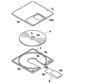
以下、図面を参照して本発明のディスクカートリッジの実施の形態を詳細に説明する。図1は本発明のディスクカートリッジの分解斜視図である。図1のディスクカートリッジ1は、たとえばいわゆる3.5インチタイプのフロッピー(登録商標)ディスクカートリッジであり、上シェル2および下シェル3を接合して形成された扁平なケースCと、ケースC内に回転自在に収容された円盤状の情報記録媒体5とを備えている。
Hereinafter, embodiments of the disk cartridge of the present invention will be described in detail with reference to the drawings. FIG. 1 is an exploded perspective view of a disk cartridge of the present invention. A disk cartridge 1 in FIG. 1 is a so-called 3.5-inch type floppy (registered trademark) disk cartridge, for example, a flat case C formed by joining an
上シェル2および下シェル3は扁平な略矩形状に形成されており、たとえば合成樹脂から形成されている。上シェル2および下シェル3の外周には側壁を構成する外周リブ2a、3aが形成されており、この外周リブ2a、3aとを突き合わせた状態で接合することにより、情報記録媒体5を収容する空間が形成される。また、上シェル2および下シェル3には、情報記録媒体5にアクセスするための磁気ヘッド挿入用窓部2b、3bが略長方形状に設けられており、さらにこの窓部2b、3bを開閉可能なシャッター6が設けられる。
The
情報記録媒体5は、たとえばプラスチックフィルムの両面に磁性材を塗布した可撓性を有する磁気ディスクであって、ケースC内に回転自在に収容されている。情報記録媒体5における中心部の下面側にセンターコア10の上面10aが固定されている。ここで、下シェル3の中央部分には、センターコア10が外部に臨む大きさの円形状のスピンドル孔3cが形成されており、スピンドル孔3cからセンターコア10の下面側が露出するようになっている。そして、ディスクカートリッジ1がディスクドライブ装置に装填されたときに、センターコア10がディスクドライブ装置のスピンドルがセンターコア10を保持する。スピンドルがセンターコア10を回転させたとき、センターコア10と固着している情報記録媒体5が回転するようになっている。
The information recording
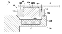
図2はディスクドライブのスピンドルにチャッキングされた状態でのセンターコア10の周辺部位の一部を模式的に示した断面図である。図2のセンターコア10は、たとえば円筒状に成形された金属部材10Mをインサートした金型に、プラスチック等のポリマー、ゴム、エラストマ等からなる樹脂を注入することにより成形されたものである。ここで、金属部材10Mは上面10aに露出した平坦面10xを有し、この平坦面10xのみが情報記録媒体5の下面に接着部材13を用いて接着されている。接着部材としては、常液で液状の接着剤またはホットメルト接着剤を塗布したもの、フィルム基材の両面に接着層を形成したもの等を使用することができる。これにより、可撓性を有する情報記録媒体5にセンターコア10が固定されたとき、上面10aの凹凸に起因する情報記録媒体5に歪みの発生を防止することができる。つまり、金属部材10Mと樹脂10Pとの平坦加工性を比較した場合、金属部材10Mの方が樹脂10Pよりも平坦に加工しやすい特性を有している。したがって、平坦面10xの平坦度は、上面10aの樹脂部分によりも高い。したがって、平坦性の高い金属部材10Mの平坦面10xのみが情報記録媒体5に接着することにより、情報記録媒体5に歪みが発生するのを防止することができる。
FIG. 2 is a cross-sectional view schematically showing a part of the peripheral portion of the
さらに、センターコア10は、平坦面10xが上面10aにおいて平坦面10xを囲う樹脂10Pに対し高さdだけ突出した構造を有している。これにより、情報記録媒体5が、平坦度の低い上面10aの樹脂部分に接触していないか、または接触しにくくすることができるため、上面10aの樹脂部分の凹凸が情報記録媒体5に転移し、情報記録媒体5に歪みが発生するのを防止することができる。
Further, the
一方、センターコア10の下面10b側においても、金属部材10Mが露出した構造を有している。そして、軸CLを中心として回転するディスクドライブのスピンドル50に設けられた磁石が下面10bから露出した金属部材10Mを磁気吸着することにより、センターコア10を保持するようになっている。なお、上述のように、センターコア10の上面10aおよび下面10bから金属部材10Mを露出させるようにしているため、金属部材10Mのセンターコア10に占める割合は大きいものとなる。よって、センターコア10の着磁力が向上し、スピンドル50がセンターコア10を保持しやすくなる。
On the other hand, the
また、下面10bの外周側には、スピンドル50に機械的に接続されるギア部10Gが樹脂10Pにより形成されている。そして、スピンドル50がセンターコア10を磁気吸着力により保持したときに、このギア部10Gがスピンドル50のギア部51に噛み合うようになっている。すると、スピンドル50がセンターコア10を回転させたとき、センターコア10がスピンドル50に対して滑るのを防止することができる。
A
なお、図2においては、下面10b側にギア部10Gが形成されている場合について例示しているが、図3に示すように、スピンドル50がセンターコア10を磁気吸着力により保持したときにスピンドル50と接触する接触部10Tをセンターコア10の下面側の最外周領域に形成してもよい。この接触部10Tは樹脂10Pからなっているため摩擦力が大きく、スピンドル50がセンターコア10を回転させたとき、接触部10Tの摩擦力により、センターコア10がスピンドル50に対して滑るのを防止することができる。
2 illustrates the case where the
上記各実施の形態によれば、センターコア10が、金属部材10Mを金型にインサートし、金型に樹脂を注入することにより成形されたものであって、金属部材10Mが、上面10aに露出した平坦面10xを有し、平坦面10xのみが情報記録媒体5の中心部の下面に接着部材13を用いて接着されていることにより、平坦加工が樹脂よりも容易な金属部材に平坦面10xを設け、上面10aの凹凸の少ない部位である平坦面のみが情報記録媒体5に接着することになるため、情報記録媒体5に歪みが発生するのを抑制することができる。
According to each of the above embodiments, the
また、平坦面10xが、平坦面10xを囲う樹脂10Pに対し突出させ、この部分で情報記録媒体5を接着部材で接着するようにすれば、情報記録媒体5が上面10aの樹脂部分に接触しないか、または接触しにくくすることができるため、上面10aの樹脂部分に形成された凹凸が情報記録媒体5に転移し、情報記録媒体5に歪みが発生するのを抑制することができる。
In addition, if the
なお、本発明の実施の形態は、上記実施の形態に限定されない。たとえば、図1においていわゆる3.5インチタイプのフロッピー(登録商標)ディスクカートリッジに本発明を適用したものであるが、本発明はその種のディスクカートリッジ1に限らず、たとえば「clik!(登録商標)」や「Pocket Zip(登録商標)」と呼ばれる、たとえば幅50mm、奥行き6、6mm、厚さ1.95mmの扁平な金属薄板からなる上下シェルを備えたハウジング内に、センターコアに固定された直径約46.5mmの磁気ディスク等の可撓性を有する磁気ディスクを回転自在に収容した超小型の磁気ディスクカートリッジやさらに直径が小さい約35.6mm、25.4mm、21.6mm等の磁気ディスクを備えたディスクカートリッジに適用してもよい。 The embodiment of the present invention is not limited to the above embodiment. For example, in FIG. 1, the present invention is applied to a so-called 3.5-inch type floppy (registered trademark) disk cartridge. However, the present invention is not limited to such a disk cartridge 1, and for example, “click! ) ”Or“ Pocket Zip (registered trademark) ”, which is fixed to the center core in a housing having upper and lower shells made of flat metal thin plates having a width of 50 mm, a depth of 6, 6 mm, and a thickness of 1.95 mm, for example. An ultra-small magnetic disk cartridge that rotatably accommodates a flexible magnetic disk such as a magnetic disk having a diameter of about 46.5 mm, and magnetic disks having a smaller diameter of about 35.6 mm, 25.4 mm, 21.6 mm, etc. You may apply to the disk cartridge provided with.
1 ディスクカートリッジ
2 上シェル
2b 窓部
3 下シェル
5 情報記録媒体
6 シャッター
10G ギア部
10 センターコア
10a 上面
10b 下面
10M 金属部材
10P 樹脂
10x 平坦面
13 接着部材
C ケース
DESCRIPTION OF SYMBOLS 1
Claims (2)
前記センターコアが、金属部材を金型にインサートし、該金型に樹脂を注入することにより成形されたものであって、
前記金属部材が、前記上面に露出した平坦面を有し、
該平坦面のみが前記情報記録媒体の中心部の下面に前記接着部材を用いて接着されていることを特徴とするディスクカートリッジ。 A disc cartridge comprising a disc-shaped information recording medium having flexibility and having a center core in a central portion in a flat case, wherein the disc cartridge is rotatable. In the disk cartridge in which the upper surface side of the center core is fixed using an adhesive member,
The center core is formed by inserting a metal member into a mold and injecting resin into the mold,
The metal member has a flat surface exposed on the upper surface;
Only the flat surface is bonded to the lower surface of the central portion of the information recording medium using the bonding member.
Priority Applications (1)
| Application Number | Priority Date | Filing Date | Title |
|---|---|---|---|
| JP2004111100A JP2005293799A (en) | 2004-04-05 | 2004-04-05 | Disk cartridge |
Applications Claiming Priority (1)
| Application Number | Priority Date | Filing Date | Title |
|---|---|---|---|
| JP2004111100A JP2005293799A (en) | 2004-04-05 | 2004-04-05 | Disk cartridge |
Publications (1)
| Publication Number | Publication Date |
|---|---|
| JP2005293799A true JP2005293799A (en) | 2005-10-20 |
Family
ID=35326541
Family Applications (1)
| Application Number | Title | Priority Date | Filing Date |
|---|---|---|---|
| JP2004111100A Withdrawn JP2005293799A (en) | 2004-04-05 | 2004-04-05 | Disk cartridge |
Country Status (1)
| Country | Link |
|---|---|
| JP (1) | JP2005293799A (en) |
-
2004
- 2004-04-05 JP JP2004111100A patent/JP2005293799A/en not_active Withdrawn
Similar Documents
| Publication | Publication Date | Title |
|---|---|---|
| JPS63117380A (en) | Information storage medium | |
| JP2005293799A (en) | Disk cartridge | |
| JP2006134453A (en) | Disk cartridge | |
| US4704649A (en) | Magnetic disk cartridge | |
| JP3936703B2 (en) | Optical disc and disc cartridge containing the optical disc | |
| JPS62222475A (en) | Information storage medium | |
| TWI286745B (en) | Optical disc and apparatus for portable applications | |
| JP2006338774A (en) | Hologram media cartridge | |
| JP2005267740A (en) | Disk cartridge | |
| JP2003162879A (en) | Disk-like magnetic recording medium | |
| JP2004103122A (en) | Chucking structure for center core of disk cartridge | |
| WO2002089137A1 (en) | Optical information recording medium and optical information recording/reproduction apparatus | |
| JP2005276399A (en) | Disk cartridge | |
| JPS62157380A (en) | Magnetic disk cartridge | |
| JP2004342251A (en) | Disk cartridge | |
| JP5141172B2 (en) | Storage tray | |
| JPH0416255Y2 (en) | ||
| JPH10302432A (en) | Disk cartridge | |
| JP2004079028A (en) | Center core of disk cartridge | |
| JP2005100594A (en) | Magnetic disk cartridge | |
| JPS63229675A (en) | Disk cartridge | |
| KR20060064495A (en) | Compact optical / magnetic discs for data storage | |
| JP2004145924A (en) | Disk cartridge | |
| JP2004103123A (en) | Magnetic disk cartridge | |
| JP2005310299A (en) | Disk cartridge |
Legal Events
| Date | Code | Title | Description |
|---|---|---|---|
| A711 | Notification of change in applicant |
Free format text: JAPANESE INTERMEDIATE CODE: A712 Effective date: 20061207 |
|
| A300 | Withdrawal of application because of no request for examination |
Free format text: JAPANESE INTERMEDIATE CODE: A300 Effective date: 20070605 |