JP2005293767A - Magneto-optical recording medium heat treatment apparatus - Google Patents
Magneto-optical recording medium heat treatment apparatus Download PDFInfo
- Publication number
- JP2005293767A JP2005293767A JP2004109959A JP2004109959A JP2005293767A JP 2005293767 A JP2005293767 A JP 2005293767A JP 2004109959 A JP2004109959 A JP 2004109959A JP 2004109959 A JP2004109959 A JP 2004109959A JP 2005293767 A JP2005293767 A JP 2005293767A
- Authority
- JP
- Japan
- Prior art keywords
- groove
- land
- magneto
- recording medium
- heat treatment
- Prior art date
- Legal status (The legal status is an assumption and is not a legal conclusion. Google has not performed a legal analysis and makes no representation as to the accuracy of the status listed.)
- Pending
Links
Images

Abstract
【課題】 情報トラックにアニールされた領域が生じることなく、かつ一つの媒体に対してアニール処理する時間が短時間で済む、光磁気記録媒体の加熱処理装置を提供する。
【解決手段】 メインビーム31と2つのサブビーム32,33を光磁気記録媒体に照射する3ビーム加熱処理装置であって、メインビーム31でランド21またはグルーブ22にトラッキングを掛け、トラッキングを掛けられたランド21またはグルーブ22の両側の側壁部23をそれぞれサブビーム32,33で加熱処理する。
【選択図】 図2
PROBLEM TO BE SOLVED: To provide a heat treatment apparatus for a magneto-optical recording medium, in which an annealed area is not generated in an information track and a time for annealing a medium is short.
A three-beam heating apparatus for irradiating a magneto-optical recording medium with a main beam 31 and two sub-beams 32 and 33. The main beam 31 is used to track a land 21 or a groove 22 to be tracked. The side walls 23 on both sides of the land 21 or the groove 22 are heated by the sub beams 32 and 33, respectively.
[Selection] Figure 2
Description
本発明は、磁性薄膜に情報を記録する光磁気記録媒体に関し、特に、記録した情報を磁壁移動再生方式により再生する光磁気記録媒体に関する。 The present invention relates to a magneto-optical recording medium for recording information on a magnetic thin film, and particularly to a magneto-optical recording medium for reproducing recorded information by a domain wall moving reproduction method.
光磁気記録媒体における、書き換え可能な高密度記録方式として、半導体レーザの熱エネルギーを用いて磁性薄膜に磁区を書き込むことで情報を記録し、光磁気効果を用いて情報を読み出すものがある。近年、この方式を用いた光磁気記録媒体の記録密度を更に高めて大容量の記録媒体を実現しようとする要求が高まっている。 As a rewritable high-density recording method in a magneto-optical recording medium, there is a method in which information is recorded by writing magnetic domains in a magnetic thin film using thermal energy of a semiconductor laser and information is read out using a magneto-optical effect. In recent years, there has been a growing demand to further increase the recording density of a magneto-optical recording medium using this method to realize a large-capacity recording medium.
光磁気記録媒体である光磁気ディスクの線記録密度は、再生光学系のレーザ波長と、対物レンズの開口数に大きく依存する。しかし、再生光学系のレーザ波長や対物レンズの開口数の改善には限界がある。そのため、記録媒体の構成や読み取り方法を工夫することで記録密度を改善する技術が開発されている。 The linear recording density of a magneto-optical disk that is a magneto-optical recording medium greatly depends on the laser wavelength of the reproducing optical system and the numerical aperture of the objective lens. However, there is a limit to improving the laser wavelength of the reproducing optical system and the numerical aperture of the objective lens. Therefore, a technique for improving the recording density by devising the configuration of the recording medium and the reading method has been developed.
例えば、特許文献1に開示されている技術がある。それによれば、磁気的に結合された磁壁移動層と記録保持層とを有する多層膜の構成において、情報は記録保持層に記録される。そして、情報再生時には、光ビームの照射による温度勾配を利用して、記録保持層に記録した情報を変化させることなく、磁壁移動層の記録マークの磁壁を移動させる。そして、光ビームスポットの一部領域が同一の磁化になるように磁壁移動層を磁化させて、光ビーム反射光の偏光面の変化を検出することにより、光の回折限界以下の記録マークを再生する。 For example, there is a technique disclosed in Patent Document 1. According to this, information is recorded in the recording and holding layer in the configuration of the multilayer film having the magnetically coupled domain wall motion layer and the recording and holding layer. At the time of information reproduction, the magnetic wall of the recording mark of the magnetic domain wall moving layer is moved without changing the information recorded on the recording holding layer by using the temperature gradient caused by the irradiation of the light beam. Then, the domain wall moving layer is magnetized so that the partial region of the light beam spot has the same magnetization, and the change in the polarization plane of the reflected light beam is detected, thereby reproducing the recording mark below the light diffraction limit. To do.
この方法によれば、光の回折限界以下の記録マークの再生が可能であり、記録密度及び転送速度が大幅に向上した光磁気記録媒体及びその再生方法が実現可能である。 According to this method, it is possible to reproduce a recording mark below the diffraction limit of light, and it is possible to realize a magneto-optical recording medium and a reproducing method thereof in which recording density and transfer speed are greatly improved.
なお、この光磁気記録媒体では、光ビームの照射による温度勾配を利用して磁壁移動層における記録マークの磁壁の移動を起こり易くするために、情報記録再生トラックを挟む両隣接グルーブに高パワーのレーザ光を照射することでグルーブを高温加熱処理(以下、アニール処理と称する)し、グルーブ部分の記録媒体層を変質させるアニール処理が施されている。このアニール処理により、記録マークを形成する磁壁が閉じた磁区にならないという効果を得ることができる。これにより、隣接する情報トラックの磁性層間の結合が消失するので、より安定した磁壁の移動が可能である。このアニール処理により良好な再生信号を得ることができる。 In this magneto-optical recording medium, in order to facilitate the movement of the domain wall of the recording mark in the domain wall moving layer using the temperature gradient caused by the irradiation of the light beam, high power is applied to both adjacent grooves sandwiching the information recording / reproducing track. The groove is subjected to a high temperature heating process (hereinafter referred to as an annealing process) by irradiating a laser beam, and an annealing process is performed to alter the recording medium layer in the groove part. By this annealing treatment, it is possible to obtain an effect that the domain wall forming the recording mark does not become a closed magnetic domain. As a result, since the coupling between the magnetic layers of the adjacent information tracks disappears, the domain wall can be moved more stably. A good reproduction signal can be obtained by this annealing treatment.
ところが、上記従来例においては、アニール処理を前提とする場合は、グルーブをアニール処理するため、情報トラックとしてランドのみ使用可能で高密度化を図ることが難しいという、課題があった。 However, in the above conventional example, when the annealing process is premised, since the groove is annealed, there is a problem that only the land can be used as an information track and it is difficult to increase the density.
また、最近では、更なる高密度化を目指して、アニール処理を必要とせず、ランド部とともにグルーブ部分も情報トラックとして使用可能な光磁気ディスクに関する研究が盛んである。これによれば、光磁気ディスクの情報トラックに対して垂直方向に高密度化が可能となるとされている。 Recently, with the aim of further increasing the density, research on a magneto-optical disk that does not require an annealing process and can use the land portion and the groove portion as an information track has been actively conducted. According to this, the density can be increased in the direction perpendicular to the information track of the magneto-optical disk.
例えば、特許文献2では、基板における溝部側壁部の表面粗さをコントロールすることにより、ランド部ばかりでなくグルーブ部も記録可能な媒体(以下、ランド・グルーブ記録媒体と称する)を実現している。 For example, Patent Document 2 realizes a medium (hereinafter referred to as a land / groove recording medium) capable of recording not only a land portion but also a groove portion by controlling the surface roughness of the groove side wall portion of the substrate. .
このようにして、従来、光磁気記録媒体のトラックは、0.5μm程度までの狭トラックピッチ化が可能となっている。実験によれば、トラックピッチ0.54μmの深溝(溝深さが約160nm)のランド・グルーブ基板を用いて、線記録密度として0.08μm/bitの記録再生が実用レベルで確認されている。これは、記録密度として15Gbit/inch2に相当する。 Thus, conventionally, the track of the magneto-optical recording medium can be narrowed down to about 0.5 μm. According to experiments, it has been confirmed that a linear recording density of 0.08 μm / bit recording / reproduction at a practical level using a land / groove substrate having a deep groove (groove depth of about 160 nm) with a track pitch of 0.54 μm. This corresponds to a recording density of 15 Gbit / inch 2 .
また、ランドとともにグルーブを記録可能とする場合は、100nm程度以上の比較的深い溝を前提としているものであり、そのため、入射光の近接場的振る舞いにより、ランド部をトレースしている時と、グルーブ部をトレースしている時で形成される温度分布が大きく異なり、特に、ランド部記録時は相対的に、グルーブ部のトレース時よりもより大きな記録パワーが必要となり、ランド部の記録を最適記録パワーで行うとグルーブ部のデータを破壊してしまう、いわゆる、クロスライトしてしまうという課題があった。 In addition, when the groove can be recorded together with the land, it is premised on a relatively deep groove of about 100 nm or more. Therefore, when the land portion is traced by the near-field behavior of incident light, The temperature distribution formed when tracing the groove part is greatly different, especially when recording the land part, relatively higher recording power is required than when tracing the groove part, and the land part recording is optimal. When the recording power is used, there is a problem that the data in the groove portion is destroyed, that is, so-called cross-writing occurs.
また、深溝基板は、成型が難しく、狭トラックピッチ化も難しいという問題がある。 Further, the deep groove substrate has a problem that it is difficult to mold and it is difficult to reduce the track pitch.
そこで、これらの課題を解決する方法として、本出願人により提案された特許文献3に示されているように、相対的な段差が記録再生に係る光源波長の1/8程度以下である、比較的浅い溝のランド部とグルーブ部を両方ともトラックとして使用するようにする為、予め、ランドとグルーブの間の境界部(以下、側壁部と称する)にレーザービーム照射のアニール処理で物性を変質させる方法によりランドとグルーブの間を磁気的に分断するようにする。 Therefore, as a method for solving these problems, as shown in Patent Document 3 proposed by the present applicant, the relative step is about 1/8 or less of the light source wavelength for recording and reproduction. In order to use both the land portion and groove portion of the shallow groove as tracks, the physical properties are altered in advance by annealing with laser beam irradiation at the boundary portion between the land and the groove (hereinafter referred to as a side wall portion). The land and the groove are magnetically separated by the method of the above.
こうすることにより、記録媒体の半径方向においてトラック間が磁気的に分断された、浅い溝を使用したランド・グルーブ記録に対応した、狭トラックピッチの、より高密度な情報記録が可能な光磁気記録媒体を提供することが可能となる。
特許文献3のようにランド・グルーブ間の側壁部をアニール処理する際、単純で効率の良い方法が検討される。そこで発明者らは上記アニール処理を鋭意検討した際、アニール処理されるレーザーパワーで、ある側壁部をアニール処理した後、その隣の側壁部をアニール処理するために、該アニール処理されるレーザーパワーのままトラックを横断(トラックジャンプとも呼ばれる。)した後に側壁部をアニール処理すると、情報記録トラック即ちランド部あるいはグルーブ部に、トラックを横断した際にアニール処理された領域が形成されてしまうことを見出し、そのために、情報トラックに記録磁区が形成されない領域が生じ、有効な記録領域が減少するという問題を懸念した。 As in Patent Document 3, a simple and efficient method is considered when annealing the side wall portion between the land and the groove. Therefore, when the inventors diligently studied the annealing treatment, after annealing one side wall portion with the laser power to be annealed, the laser power to be annealed is used to anneal the adjacent side wall portion. If the side wall portion is annealed after traversing the track as it is (also called track jump), an annealed region is formed in the information recording track, that is, the land portion or the groove portion when the track is traversed. As a result, there was a concern that a recording magnetic domain was not formed in the information track, and the effective recording area was reduced.
また、これを解決するため、情報トラックの片側の側壁部をアニール処理されるレーザーパワーでアニール処理した後、アニール処理されないレーザーパワーで情報トラックを横断した後、再度、アニール処理されるレーザーパワーで、もう片側の側壁部をアニール処理するという方法を提案した(提案番号05517165)が、この方法は一つの側壁部ごとに加熱処理方法を行わなければならず、時間のかかる工程である。 In order to solve this problem, the side wall on one side of the information track is annealed with laser power that is annealed, then traverses the information track with laser power that is not annealed, and then again with laser power that is annealed. A method of annealing the other side wall portion was proposed (suggestion number 0517165). However, this method requires a heat treatment method for each side wall portion, and is a time-consuming process.
そこで本発明の目的は、上記背景技術の実状に鑑み、情報トラックにアニールされた領域が生じることなく、かつ一つの媒体に対してアニール処理する時間が短時間で済む、光磁気記録媒体の加熱処理装置を提供することにある。 Accordingly, an object of the present invention is to heat a magneto-optical recording medium in which an annealed area is not generated in an information track and a time for annealing a single medium is short in view of the actual state of the background art described above. It is to provide a processing apparatus.
上記目的を達成するために、本発明は、ランドとグルーブの間に境界部を有し、ランドとグルーブの両方を情報トラックとして用いた光磁気記録媒体の加熱処理装置であって、複数のビーム光を用い、該複数のビーム光のうちの1本のビーム光でランドまたはグルーブにトラッキングを掛け、該トラッキングを掛けられたランドまたはグルーブの両側の境界部をそれぞれ、残りのビーム光で加熱処理することを特徴とする。このような構成では、1つの工程で情報トラックの両側の側壁部を同時に加熱処理することが可能である。 In order to achieve the above object, the present invention provides a heat treatment apparatus for a magneto-optical recording medium having a boundary portion between a land and a groove, and using both the land and the groove as an information track. Using light, the land or groove is tracked with one of the plurality of light beams, and the boundary portions on both sides of the land or groove subjected to the tracking are heated with the remaining light beams, respectively. It is characterized by doing. In such a configuration, it is possible to simultaneously heat-treat the side wall portions on both sides of the information track in one process.
また、本発明の加熱処理方法は、ランドとグルーブの両方を記録再生領域である情報トラックとして用い、該情報トラックに情報が記録され、前記情報トラックに再生用光ビームを照射することにより記録マークの磁壁を移動させ、前記再生用光ビームの反射光が有する偏光面の変化を検出することで前記情報が再生される磁壁移動型の光磁気記録媒体の前記ランドと前記グルーブの境界部をビーム光を用いて加熱処理する場合にも好適である。 In the heat treatment method of the present invention, both the land and the groove are used as information tracks that are recording / reproducing areas, information is recorded on the information tracks, and the information track is irradiated with a reproducing light beam. The boundary of the land and groove of the domain wall motion type magneto-optical recording medium on which the information is reproduced is detected by detecting the change of the polarization plane of the reflected light of the reproducing light beam. Also suitable for heat treatment using light.
本発明によれば、ランドまたはグルーブの両サイドの側壁部のみに同時にビーム光を照射することにより、1つの工程で所望の領域の側壁部の高温加熱処理が行われるので、効率よく短時間で側壁部の物性を変質させることが可能となる。また、これにより、ランド・グルーブ間を磁気的に分断するようにしたので、安定した磁壁移動再生が行えるランド・グルーブ記録対応の光磁気記録媒体を提供できる。 According to the present invention, by irradiating only the side wall portions on both sides of the land or groove with the light beam at the same time, the high-temperature heat treatment of the side wall portion in a desired region is performed in one step. It becomes possible to change the physical properties of the side wall. Further, since the land / groove is magnetically divided, a magneto-optical recording medium compatible with land / groove recording capable of stable domain wall motion reproduction can be provided.
以下、本発明の実施の形態について図面を参照して説明する。なお、以下の実施形態は一例であり、本発明はこれら実施形態により限定を受けるものではない。 Hereinafter, embodiments of the present invention will be described with reference to the drawings. In addition, the following embodiment is an example and this invention is not limited by these embodiment.
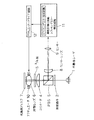
図1に本発明の一実施形態に係るアニール処理装置の構成図を示す。 FIG. 1 shows a configuration diagram of an annealing apparatus according to an embodiment of the present invention.
図1において、本実施形態のアニール処理装置は、半導体レーザ1からの光束を、回折格子(グレーティング)2で回折を受けない光束と±1次回折光である2つの光束とに分け、両光束をPBS(偏光ビームスプリッタ)3を透過させて2つの光路に分け、コリメータ4により略平行光束とし、λ/4板5を介して対物レンズ6で光磁気ディスク7上に、メインビームと2つサブビームとして集光させる構成となっている。さらに、対物レンズ6は該対物レンズを可動させるアクチュエータ10を備える。アクチュエータ10にはアクチュエータドライブ回路12が接続され、対物レンズ6の移動が制御されている。また、光磁気ディスク7で反射された光は再び対物レンズ6、λ/4板5およびコリメータ4を通りPBS3で別の光路に向けられ、センサーレンズ8を通ってセンサー9に入射する。センサー9には、極性切り替え回路及びトラッキングエラー検出回路からなるトラッキングエラー生成回路11が接続され、生成したトラッキングエラーの信号をアクチュエータードライブ回路12に出力する。アクチュエータードライブ回路12はトラッキングエラー生成回路11からの信号により対物レンズ6のアクチュエータ10を駆動し、トラッキングエラーを正す。
In FIG. 1, the annealing apparatus of this embodiment divides the light beam from the semiconductor laser 1 into a light beam that is not diffracted by the diffraction grating (grating) 2 and two light beams that are ± first-order diffracted light. The light beam is transmitted through a PBS (polarized beam splitter) 3 and divided into two optical paths. The collimator 4 converts the light beam into a substantially parallel light beam, and a main beam and two sub-beams on a magneto-optical disk 7 by an objective lens 6 via a λ / 4
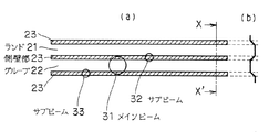
光磁気ディスク7は、図2に示すように、ランド・グルーブ記録に対応したランド21とグルーブ22、及びランドとグルーブ間の側壁部23(即ちランドとグルーブの境界部)からなる。対物レンズ6で集光されたビームは、メインビーム31と2つのサブビーム32、33からなり、メインビーム31は情報トラックであるグルーブ22へ、サブビーム32とサブビーム33はそれぞれ、グルーブ22の両サイドの側壁部23へ集光されている。なお、メインビーム31がランド21に集光されるとき、サブビーム32、33はそれぞれランド21の両サイドの側壁部23へ集光される。
As shown in FIG. 2, the magneto-optical disk 7 includes lands 21 and grooves 22 corresponding to land / groove recording, and a
こうして、高強度の微小スポット(サブビーム32、33)で側壁部23をアニール処理する。
In this way, the
DWDD(Domain Wall Displacement Detection)方式で再生が可能な光磁気ディスクにおいて、DWDD動作をスムーズに行わせるためには、情報トラック間(ランドとグルーブの間の側壁部)を熱処理する必要があるが、この熱処理幅はできるだけ狭いほうが、トラックピッチを狭めることができ、高密度化が可能となる。狭い幅の熱処理を行うために本願の光ディスク熱処理装置では、半導体レーザ1の波長は500nm以下の短波長レーザを使用することが望ましい。 In a magneto-optical disk that can be reproduced by a DWDD (Domain Wall Displacement Detection) method, in order to perform DWDD operation smoothly, it is necessary to heat-treat between information tracks (side walls between lands and grooves). When the heat treatment width is as narrow as possible, the track pitch can be narrowed and the density can be increased. In order to perform a heat treatment with a narrow width, it is desirable to use a short wavelength laser whose wavelength of the semiconductor laser 1 is 500 nm or less in the optical disk heat treatment apparatus of the present application.
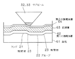
また高NAの対物レンズ(例えばNA=0.85)を使用し、ビームスポットを狭めることも有効である。高NAの対物レンズを使用する上で、本発明の光ディスク熱処理装置では、光磁気ディスクの記録層が形成されている側から熱処理用光ビームを照射し、ディスクが傾いても、収差でビームスポットが歪むことを避けている。(図5参照)
基板越しに光を投入させると、特に高NAの対物レンズを使用しているときには、基板の厚みの変化でフォーカスずれが生じたり、ディスクの傾きでコマ収差が発生し、良好な熱処理をすることが困難となるからである。
It is also effective to use a high NA objective lens (for example, NA = 0.85) and narrow the beam spot. When using a high NA objective lens, the optical disk heat treatment apparatus of the present invention irradiates a heat treatment light beam from the side on which the recording layer of the magneto-optical disk is formed. To avoid distortion. (See Figure 5)
When light is thrown through the substrate, especially when using a high NA objective lens, defocusing occurs due to changes in the thickness of the substrate, or coma occurs due to the tilt of the disk, and good heat treatment is performed. This is because it becomes difficult.
本実施形態においては、高強度の微小スポット(サブビーム32、33)を得るために、半導体レーザ1の波長を405nmとし、対物レンズ6は、NA(開口数)=0.85を採用した。 In this embodiment, in order to obtain a high-intensity minute spot (sub beams 32 and 33), the wavelength of the semiconductor laser 1 is set to 405 nm, and the objective lens 6 employs NA (numerical aperture) = 0.85.
熱処理条件は、光磁気ディスク7の回転速度2〜6 m/sで、サブビーム強度4 mW 〜 7 mW程度の間の最適値を捜して設定した。また、強度は、図5の誘電体保護層64の厚さを選定し、反射率を調整することによっても制御できる。
The heat treatment conditions were set by searching for an optimum value between about 4 mW and 7 mW at a rotational speed of the magneto-optical disk 7 of 2 to 6 m / s. The strength can also be controlled by selecting the thickness of the dielectric
このとき、メインビームとサブビームの強度比は、0.1〜0.2:1程度になるように設定されており、結果、ランド21とグルーブ22にはアニール処理の影響は出ないようになっている。 At this time, the intensity ratio between the main beam and the sub beam is set to be about 0.1 to 0.2: 1. As a result, the land 21 and the groove 22 are not affected by the annealing process. ing.
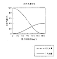
サブビーム(1次回折光)とメインビーム(0次回折光)との前記強度比は、図4に示すように格子の位相差を180deg近傍にすれば、1次光と0次光の強度比が所望の比率になる設定できる。 The intensity ratio between the sub beam (first-order diffracted light) and the main beam (0th-order diffracted light) is desired to be the intensity ratio between the first-order light and the 0th-order light if the phase difference of the grating is close to 180 degrees as shown in FIG. Can be set to a ratio of
次に復路であるが、光磁気ディスク7で反射された3つのビームは、PBS 3で反射させられ、センサーレンズ8でセンサー9に集光させられる。 Next, on the return path, the three beams reflected by the magneto-optical disk 7 are reflected by the PBS 3 and condensed on the sensor 9 by the sensor lens 8.
そして、ダブルスパイラルの場合、センサー9より得られる出力信号よりトラッキングエラーを検出し、メインビームが照射されているトラックの両サイドの側壁部23のアニール処理を連続して行える。所望の領域、例えば、ディスク内周から外周まで行える。アニールパワー、線速度等は予め、条件を変えてアニール処理を行って、情報トラックの記録再生特性を評価して決める。
In the case of the double spiral, a tracking error is detected from the output signal obtained from the sensor 9, and the annealing treatment of the
ところで、本実施形態における光磁気ディスク7は、波長660nm、対物レンズNA=0.60での記録再生用のものであり、グルーブピッチは1.0μm、ランド・グルーブ幅比約1:1、グルーブ深さは約50nm、側壁の傾斜角は約40°である。この場合、半導体レーザの波長405nm、対物レンズの開口数NA=0.85とした場合のスポットでは、通常のプッシュプル信号は得られない。そこで、プッシュプル信号を得るために、図2に示すように、メインビーム31を太らせている。これは、図3に示した回折格子2における0次光用開口部の大きさD1を選定することにより可能である。 By the way, the magneto-optical disk 7 in this embodiment is for recording and reproduction with a wavelength of 660 nm and an objective lens NA = 0.60, the groove pitch is 1.0 μm, the land / groove width ratio is about 1: 1, and the groove. The depth is about 50 nm, and the inclination angle of the side wall is about 40 °. In this case, a normal push-pull signal cannot be obtained at a spot where the wavelength of the semiconductor laser is 405 nm and the numerical aperture NA of the objective lens is 0.85. Therefore, in order to obtain a push-pull signal, the main beam 31 is thickened as shown in FIG. This is possible by selecting the size D1 of the 0th-order light opening in the diffraction grating 2 shown in FIG.
本実施形態では、メインビームは、半導体レーザの波長405nm、対物レンズ開口数NA=0.55〜0.60程度とした場合のスポットになるようにしている。そのために、図3に示すようなグレーティングを用いている。 In this embodiment, the main beam is a spot when the wavelength of the semiconductor laser is 405 nm and the objective lens numerical aperture NA is about 0.55 to 0.60. For this purpose, a grating as shown in FIG. 3 is used.
図3において、点線の円44は、対物レンズ6の入射瞳に相当する回折格子上の光束径Dを示している。光束径D、D1、D2の大きさの関係は、D2>D>D1を満たすように選定される。グレーティングが形成されない領域43は、グレーティングの形成された領域42それよりも小さい領域に形成され、結果、0次光束は、対物レンズ6の入射瞳時点で入射瞳よりも細い光束となり、低NAで絞られたビームが光磁気ディスク7上に集光する。
In FIG. 3, a
尚、メインビームをランド部あるいはグルーブ部上にトラッキングする方法は、従来技術であるプッシュプル法を適用することにより可能である。 A method of tracking the main beam on the land portion or the groove portion can be performed by applying a push-pull method that is a conventional technique.
本発明の製造方法を特開平6−290496号に提案されている媒体に、特開2000−207791号、特開2000−187898号に提案されている記録媒体を適用した例について説明する。この場合、記録層63として少なくとも、第1、第2、第3、第4、第5の磁性層が順次積層されている磁性多層膜を用いる。第1の磁性層、第2の磁性層は、周囲温度近傍の温度において、第5の磁性層に比べて相対的に磁壁抗磁力が小さい磁性膜からなり、第4の磁性層は、第1、第2、第3及び第5の磁性層よりもキュリー温度の低い磁性膜からなり、第5の磁性層は垂直磁化膜からなっている。 An example in which the recording medium proposed in Japanese Patent Application Laid-Open Nos. 2000-207791 and 2000-187898 is applied to the medium proposed in Japanese Patent Application Laid-Open No. 6-290496 will be described. In this case, a magnetic multilayer film in which at least the first, second, third, fourth, and fifth magnetic layers are sequentially stacked is used as the recording layer 63. The first magnetic layer and the second magnetic layer are made of a magnetic film having a magnetic domain coercive force relatively smaller than that of the fifth magnetic layer at a temperature near the ambient temperature, and the fourth magnetic layer is composed of the first magnetic layer and the second magnetic layer. The second, third, and fifth magnetic layers are made of a magnetic film having a lower Curie temperature, and the fifth magnetic layer is made of a perpendicular magnetization film.
基板として、ポリカーボネートからなる厚さ0.6mm、ダブルスパイラル状に形成されたランドとグルーブのピッチを0.55μm、グルーブあるいはランドのみのピッチだと1.1μm、段差(深さ)を0.04μmとし、このランドとグルーブとの間の側壁部の基板表面に対する傾斜角度が約40゜になるように成形した直径64mmの基板を用いた。 The substrate is made of polycarbonate and has a thickness of 0.6 mm. The pitch between lands and grooves formed in a double spiral shape is 0.55 .mu.m. The pitch of only grooves or lands is 1.1 .mu.m, and the step (depth) is 0.04 .mu.m. The substrate having a diameter of 64 mm was used so that the inclination angle of the side wall portion between the land and the groove with respect to the substrate surface was about 40 °.
ランド・グルーブのパターン領域は、半径16mm〜30mmである。直流マグネトロンスパッタリング装置に、BドープしたSi、及びGd、Tb、Fe、Coの各ターゲットを取り付け、前記ポリカーボネイト基板を基板ホルダーに固定した後、1×10⁻⁵Pa以下の高真空になるまでチャンバー内をクライオポンプで真空排気した。真空排気をしたままArガスを0.3Paとなるまでチャンバー内に導入し、基板を回転させながら、第1の誘電体層62であるSiN層を40nm成膜した。引き続き、第1の磁性層としてGdFeCo層を18nm、第2の磁性層(遮断補助層)としてGdFeCrを18nm、第3の磁性層(後方漏れこみ抑制層)としてTbFeCoを18nm、第4の磁性層(遮断層)としてTbFe層を10nm、第5の磁性層(メモリ層)としてTbFeCo層を60nm順次成膜した。最後に、第2の誘電体層64としてSiN層を45nm成膜した。SiN層成膜時にはArガスに加えてN2 ガスを導入し、直流反応性スパッタにより成膜した。各磁性層は、Gd、Tb、Fe、Coの各ターゲットに直流パワーを印加して成膜した。
The land / groove pattern region has a radius of 16 mm to 30 mm. The B-doped Si and Gd, Tb, Fe, and Co targets are attached to a DC magnetron sputtering apparatus, and the polycarbonate substrate is fixed to the substrate holder, and then the chamber is set to a high vacuum of 1 × 10 −5 Pa or less. The inside was evacuated with a cryopump. While evacuating, Ar gas was introduced into the chamber until the pressure reached 0.3 Pa, and the SiN layer as the
各磁性層のキュリー温度は、第1の磁性層が300℃以上、第2の磁性層が220℃、第3の磁性層が180℃、第4の磁性層が160℃、第5の磁性層が330℃程度となるように設定した。各磁性層の組成は、特性が良くなる組成に調整した。その後、レーザー波長405nmの3ビームアニール装置を用いて、第2の誘電体層64側からアニール処理を行った。アニール時の線速度は、一定の4.5m/sで行った。また、サブビームのアニールパワーを、5.0mWで行った。このアニール条件は、予めアニールパワーを変えて、記録再生評価を行って求めることができる。
The Curie temperature of each magnetic layer is 300 ° C. or higher for the first magnetic layer, 220 ° C. for the second magnetic layer, 180 ° C. for the third magnetic layer, 160 ° C. for the fourth magnetic layer, and the fifth magnetic layer. Was set to about 330 ° C. The composition of each magnetic layer was adjusted to a composition with improved characteristics. Thereafter, annealing was performed from the
待機時あるいはトラックジャンプする際のサブビームのパワーは、1.5mWとした。トラッキングは、メインビームを用いて行った。最初、最内周のランド部の両サイドの側壁部にサブビームが照射されるようにトラッキングを掛けた。この時のサブビームのレーザーパワーは1.5mWである。その後、レーザーパワーを5.0mWにし、連続で各ランド部の両サイドの側壁を照射した。ダブルスパイラル状にランド・グルーブが形成されているため、トラッキングを掛けた状態で連続で最内周から最外周に向かって、各ランド部の両サイドの側壁部が同時にアニール処理される。メインビームが最外周に達したら、サブビームのレーザーパワーを待機時の1.5mWに落とし、所望の領域の側壁部すべてがアニールされ、アニール処理工程を終了した。 The power of the sub beam during standby or track jumping was 1.5 mW. Tracking was performed using the main beam. Initially, tracking was performed so that the side beams on both sides of the innermost land portion were irradiated with the sub beam. The laser power of the sub beam at this time is 1.5 mW. Thereafter, the laser power was set to 5.0 mW, and the side walls on both sides of each land portion were continuously irradiated. Since the land and groove are formed in a double spiral shape, the side wall portions on both sides of each land portion are annealed simultaneously from the innermost periphery to the outermost periphery continuously in a state where tracking is applied. When the main beam reached the outermost periphery, the laser power of the sub beam was reduced to 1.5 mW during standby, and all the side wall portions in a desired region were annealed, and the annealing process was completed.
その後、紫外線硬化樹脂をコートして本発明に係るアニール処理工程を経た情報記録媒体を作成した。その後、ランド部及びグルーブ部の記録再生特性を評価したが、すべての領域で良好な特性であった。また、ランド部及びグルーブ部には、アニール処理された領域は存在していなかった。 Then, the information recording medium which coated the ultraviolet curable resin and passed through the annealing process based on this invention was created. Thereafter, the recording / reproducing characteristics of the land portion and the groove portion were evaluated, and the characteristics were favorable in all regions. Also, no annealed regions were present in the land portion and the groove portion.
1 半導体レーザ
2 回折格子
3 PBS
4 コリメータ
5 λ/4板
6 対物レンズ
7 光磁気ディスク
8 センサーレンズ
9 センサー
10 アクチュエータ
11 トラッキングエラー生成回路
12 アクチュエータードライブ回路
21 ランド
22 グルーブ
23 側壁部
31 メインビーム
32、33 サブビーム
61 基板
62 第1の誘電体層
63 記録層
64 第2の誘電体層
1 Semiconductor laser 2 Diffraction grating 3 PBS
4
Claims (3)
複数のビーム光を用い、該複数のビーム光のうちの1本のビーム光でランドまたはグルーブにトラッキングを掛け、該トラッキングを掛けられたランドまたはグルーブの両側の境界部をそれぞれ、残りのビーム光で加熱処理する、光磁気記録媒体の加熱処理装置。 A heat treatment apparatus for a magneto-optical recording medium having a boundary portion between a land and a groove, and using both the land and the groove as an information track,
Using a plurality of light beams, tracking the land or groove with one light beam of the plurality of light beams, and the remaining light beams at the boundary portions on both sides of the land or groove subjected to the tracking. A heat treatment apparatus for a magneto-optical recording medium that performs heat treatment with
複数のビーム光を用い、該複数のビーム光のうちの1本のビーム光でランドまたはグルーブにトラッキングを掛け、該トラッキングを掛けられたランドまたはグルーブの両側の境界部をそれぞれ、残りのビーム光で加熱処理する、光磁気記録媒体の加熱処理装置。 Both the land and the groove are used as an information track that is a recording / reproducing area, information is recorded on the information track, and the reproducing light beam is irradiated to the information track to move the domain wall of the recording mark, thereby reproducing the reproducing light. An apparatus that heats the boundary between the land and the groove of the domain wall motion type magneto-optical recording medium on which the information is reproduced by detecting a change in the polarization plane of the reflected beam. And
Using a plurality of light beams, tracking the land or groove with one light beam of the plurality of light beams, and the remaining light beams at the boundary portions on both sides of the land or groove subjected to the tracking. A heat treatment apparatus for a magneto-optical recording medium that performs heat treatment with
Priority Applications (1)
| Application Number | Priority Date | Filing Date | Title |
|---|---|---|---|
| JP2004109959A JP2005293767A (en) | 2004-04-02 | 2004-04-02 | Magneto-optical recording medium heat treatment apparatus |
Applications Claiming Priority (1)
| Application Number | Priority Date | Filing Date | Title |
|---|---|---|---|
| JP2004109959A JP2005293767A (en) | 2004-04-02 | 2004-04-02 | Magneto-optical recording medium heat treatment apparatus |
Publications (1)
| Publication Number | Publication Date |
|---|---|
| JP2005293767A true JP2005293767A (en) | 2005-10-20 |
Family
ID=35326524
Family Applications (1)
| Application Number | Title | Priority Date | Filing Date |
|---|---|---|---|
| JP2004109959A Pending JP2005293767A (en) | 2004-04-02 | 2004-04-02 | Magneto-optical recording medium heat treatment apparatus |
Country Status (1)
| Country | Link |
|---|---|
| JP (1) | JP2005293767A (en) |
-
2004
- 2004-04-02 JP JP2004109959A patent/JP2005293767A/en active Pending
Similar Documents
| Publication | Publication Date | Title |
|---|---|---|
| US6999398B2 (en) | Method and apparatus for recording information on information recording medium | |
| EP1552509A1 (en) | High track density super resolution mo-rom medium | |
| TW565827B (en) | Method for annealing domain wall displacement type magneto-optical disc and magneto-optical disc | |
| JP3442296B2 (en) | Magneto-optical head device and recording / reproducing device | |
| WO2002086882A1 (en) | Magneto-optic record medium | |
| US20030202430A1 (en) | Domain wall displacement type magneto-optical recording medium and method of producing same | |
| JPH06259799A (en) | Optical disk reproducing method and reproducing apparatus | |
| US6747919B2 (en) | Magneto-optical recording medium, and method and apparatus for producing the same | |
| US7126886B2 (en) | Magneto-optical recording medium and method for producing the same | |
| JP2005293767A (en) | Magneto-optical recording medium heat treatment apparatus | |
| WO2006109446A1 (en) | Magnetic recording medium, its recording/reproducing method, and recording/reproducing device | |
| US20040081032A1 (en) | Annealed magnetic domain wall displacement type magneto-optical recording medium | |
| US7376055B2 (en) | Method of annealing optical recording medium | |
| JP3733961B2 (en) | Magneto-optical recording medium using domain wall motion detection method and manufacturing method thereof | |
| JP2001184801A (en) | Optical recording medium and recording / reproducing device | |
| EP0393652A3 (en) | Magneto-optical recording and reproducing method, magnetooptical memory apparatus | |
| JP3770385B2 (en) | Magneto-optical disk reproducing method and magneto-optical disk apparatus | |
| JPWO2002089129A1 (en) | Optical recording medium, method for manufacturing optical recording medium, optical recording method and optical reproducing method for optical recording medium | |
| JP3071677B2 (en) | Optical disk medium and its recording / reproducing device | |
| JP2005285189A (en) | Method for heat treatment of magneto-optical recording medium | |
| JP4302333B2 (en) | Optical disc apparatus and information processing method thereof | |
| JP2002032941A (en) | Head position adjusting method and recording / reproducing apparatus | |
| JPH1083589A (en) | Magneto-optical recording medium | |
| JP2006048922A (en) | Optical recording medium | |
| JP2004227636A (en) | Magneto-optical recording medium |