JP2005293757A - Optical recording medium and manufacturing method thereof - Google Patents
Optical recording medium and manufacturing method thereof Download PDFInfo
- Publication number
- JP2005293757A JP2005293757A JP2004109425A JP2004109425A JP2005293757A JP 2005293757 A JP2005293757 A JP 2005293757A JP 2004109425 A JP2004109425 A JP 2004109425A JP 2004109425 A JP2004109425 A JP 2004109425A JP 2005293757 A JP2005293757 A JP 2005293757A
- Authority
- JP
- Japan
- Prior art keywords
- recording medium
- optical recording
- hard coat
- coat layer
- layer
- Prior art date
- Legal status (The legal status is an assumption and is not a legal conclusion. Google has not performed a legal analysis and makes no representation as to the accuracy of the status listed.)
- Pending
Links
Images


Landscapes
- Optical Record Carriers And Manufacture Thereof (AREA)
- Manufacturing Optical Record Carriers (AREA)
Abstract
【課題】 表面の突起を埋め込むようにハードコート層を厚く形成することなく、ハードコート層の形成に伴うエラーレートの増加を抑制することができるようにする。
【解決手段】 情報信号の記録および/または再生をするための光が照射される信号面に樹脂を均一に塗布し、信号面に塗布された樹脂を硬化して、信号面にある突起の高さ以下の厚さを有するハードコート層5を形成する。これにより、突起をエンハンスすることなく、ハードコート層5を信号面に形成できる。
【選択図】 図1PROBLEM TO BE SOLVED: To suppress an increase in error rate due to formation of a hard coat layer without forming a hard coat layer thick so as to bury a protrusion on the surface.
A resin is uniformly applied to a signal surface irradiated with light for recording and / or reproducing information signals, and the resin applied to the signal surface is cured to increase the height of protrusions on the signal surface. A hard coat layer 5 having a thickness equal to or less than that is formed. Thereby, the hard coat layer 5 can be formed on the signal surface without enhancing the protrusions.
[Selection] Figure 1
Description
この発明は、ハードコート層を有する光記録媒体およびその製造方法に関する。 The present invention relates to an optical recording medium having a hard coat layer and a method for producing the same.
従来、光記録媒体としては、光透過性を有するプラスチックディスク基板の一主面に情報信号部を形成し、この情報信号部を覆うように保護膜を形成したものが知られている。この光記録媒体では、プラスチックディスク基板側からレーザ光を情報信号部に対して照射することにより情報信号の記録または再生が行われる。 Conventionally, an optical recording medium is known in which an information signal portion is formed on one main surface of a plastic disk substrate having optical transparency, and a protective film is formed so as to cover the information signal portion. In this optical recording medium, information signals are recorded or reproduced by irradiating the information signal portion with laser light from the plastic disk substrate side.
ところで、このような光記録媒体では、記憶容量の大容量化をする場合、レーザ光を透過させるプラスチックディスク基板の厚みをより薄くする必要がある。しかし、一般に、プラスチックディスク基板は射出成形により形成されるため、射出材料(溶融樹脂等)の流動むらなどが生じ易く、プラスチックディスク基板の厚みを高精度に薄くすることが困難である。また、一般に、情報記録部はプラスチックディスク基板の凹凸構造領域に形成されるが、プラスチックディスク基板を薄くすると、凹凸構造領域を高精度に形成することも困難となる。 By the way, in such an optical recording medium, when increasing the storage capacity, it is necessary to make the thickness of the plastic disk substrate through which the laser light is transmitted thinner. However, in general, since the plastic disk substrate is formed by injection molding, unevenness in the flow of the injection material (molten resin or the like) is likely to occur, and it is difficult to reduce the thickness of the plastic disk substrate with high accuracy. In general, the information recording unit is formed in the concavo-convex structure region of the plastic disk substrate. However, if the plastic disk substrate is thinned, it becomes difficult to form the concavo-convex structure region with high accuracy.
そこで、近年では、プラスチックディスク基板に形成された情報信号部上に、レーザ光を透過可能な光透過層を設け、この光透過層側からレーザ光を情報信号部に対して照射することにより情報信号の記録または再生を行うようにした光記録媒体が提案されている。この光記録媒体では、光透過層を容易に薄くすることができるため、記憶容量の大容量化を達成することができる。 Therefore, in recent years, a light transmission layer capable of transmitting laser light is provided on the information signal portion formed on the plastic disk substrate, and the information signal portion is irradiated with the laser light from the light transmission layer side for information. There has been proposed an optical recording medium in which a signal is recorded or reproduced. In this optical recording medium, the light transmission layer can be easily made thin, so that the storage capacity can be increased.
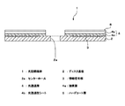
ところで、この光記録媒体では、光透過性シートを、光透過性を有する接着層を介してディスク基板の一主面に貼り合わせることにより形成される。この接着層としては、感圧性接着剤または紫外線硬化樹脂などが用いられる。また、光透過性シートとしては、通常プラスチック材料が用いられる。 By the way, this optical recording medium is formed by bonding a light-transmitting sheet to one main surface of a disk substrate through a light-transmitting adhesive layer. As the adhesive layer, a pressure-sensitive adhesive or an ultraviolet curable resin is used. In addition, a plastic material is usually used as the light transmissive sheet.
ところが、上述の光記録媒体は、光透過性シートの表面が柔らかいために、何らかの衝撃で異物がシート表面に接触した場合または、シート表面に付着したゴミをクリーニングした場合に、シート表面に傷がついてしまう可能性が高いという問題がある。 However, since the optical recording medium described above has a soft surface, the surface of the sheet is damaged when a foreign object comes into contact with the surface of the sheet by some impact or when dust attached to the surface of the sheet is cleaned. There is a problem that there is a high possibility of being stuck.
そこで、この光透過性シート表面を傷や汚れから保護するために、紫外線硬化樹脂からなるハードコート層を設けることが提案されている。このハードコート層の形成方法としては、基板側からレーザ光を照射して情報信号の記録または再生が行われる光記録媒体において、従来より用いられている方法を使用できる(例えば、特許文献1参照)。 Accordingly, it has been proposed to provide a hard coat layer made of an ultraviolet curable resin in order to protect the surface of the light transmissive sheet from scratches and dirt. As a method for forming the hard coat layer, a conventionally used method can be used in an optical recording medium on which information signals are recorded or reproduced by irradiating a laser beam from the substrate side (see, for example, Patent Document 1). ).
ところが、光透過性シートの製造工程において、光透過性シート表面に無数の微小な突起(例えば、高さは1um(ミクロン)前後)が形成された場合、ハードコート層の形成により以下のような問題が生じる。すなわち、紫外線硬化樹脂によりハードコート層を形成すると、ハードコート層により微小な突起がエンハンスされてしまい、レンズ効果によりレーザ光が記録面にうまく集光せず、光記録媒体全体のエラーレートが増加してしまうという問題が生じる。 However, when innumerable minute protrusions (for example, the height is around 1 μm) are formed on the surface of the light transmissive sheet in the manufacturing process of the light transmissive sheet, the following is caused by the formation of the hard coat layer. Problems arise. In other words, when a hard coat layer is formed of an ultraviolet curable resin, minute protrusions are enhanced by the hard coat layer, and the laser effect does not concentrate well on the recording surface due to the lens effect, increasing the error rate of the entire optical recording medium. The problem of end up occurs.
図7は、高さ1um前後の突起104cがある光透過性シート104b上に、厚さ1〜2umのハードコート層105が形成された光記録媒体の模式的断面図である。この光記録媒体は、図示を省略した基板上に、情報信号部103、光透過層104、ハードコート層105が順次積層されて構成される。また、光透過層104は、接着層104aおよび光透過性シート104bとから構成される。
FIG. 7 is a schematic cross-sectional view of an optical recording medium in which a
図7に示すように、光透過性シート104b表面に微小突起104cが形成されていると、ハードコート層105の形成により、微小突起104cが高さ、幅ともにエンハンスされてしまい、一種のレンズのようになってしまう。情報信号の読み書きをする場合に、このエンハンスされた箇所ではレーザ光が記録面に上手く集光せず、記録媒体全体のエラーが増加してしまう。
As shown in FIG. 7, when the
そこで、微小な突起104cを完全に埋め込むために、ハードコート層105を厚くしてエンハンスが起きないようにする方法が提案されている。ところが、ハードコート層105を厚くすると、膜厚の制御が困難になったり、紫外線硬化樹脂の収縮により、光記録媒体に大きな反りが発生してしまうという新たな問題が発生してしまう。
Therefore, in order to completely embed the
図8は、高さ1um前後の突起104cを有する光透過性シート104b上に、厚さ3〜6umのハードコート層105が形成された光記録媒体の模式的断面図である。光透過性シート104b表面の微小突起104cは、厚く形成されたハードコート層105により上手く埋め込まれており、情報信号の読み書きを行ってもエラーが生じない。しかし、ハードコート層105の形成方法として広く用いられているスピンコート法では、紫外線硬化樹脂の塗布厚を厚くすると、光記録媒体の内外周における紫外線硬化樹脂の厚みムラを制御することが困難になってしまう。また、塗布した紫外線硬化樹脂に紫外線を照射して硬化させると、紫外線硬化樹脂が硬化収縮するため、塗布厚を厚くすると、ハードコート形成後の光記録媒体の反りが大きくなってしまう。この反りは、ハードコート層105の厚みにほぼ比例するので、紫外線硬化樹脂の塗布厚を厚くすればするほど反りはより大きなものとなってしまう。
FIG. 8 is a schematic cross-sectional view of an optical recording medium in which a
したがって、この発明の目的は、表面の突起を埋め込むようにハードコート層を厚く形成することなく、ハードコート層の形成に伴うエラーレートの増加を抑制することができる光記録媒体およびその製造方法を提供することにある。 Therefore, an object of the present invention is to provide an optical recording medium that can suppress an increase in error rate associated with the formation of a hard coat layer without forming the hard coat layer thick so as to embed surface protrusions, and a method for manufacturing the same. It is to provide.
上記課題を解決するために、第1の発明は、情報信号の記録および/または再生をするための光が照射される信号面にハードコート層を備えた光記録媒体において、
ハードコート層の厚さが、信号面にある突起の高さ以下であることを特徴とする光記録媒体である。
In order to solve the above problems, the first invention is an optical recording medium comprising a hard coat layer on a signal surface irradiated with light for recording and / or reproducing an information signal.
The optical recording medium is characterized in that the thickness of the hard coat layer is equal to or less than the height of the protrusion on the signal surface.
第2の発明は、情報信号の記録および/または再生をするための光が照射される信号面に樹脂を塗布する工程と、
信号面に塗布された樹脂を硬化してハードコート層を形成する工程と
を備えた光記録媒体の製造方法において、
ハードコート層の厚さが信号面にある突起の高さ以下となるように、樹脂を信号面に塗布することを特徴とする光記録媒体の製造方法である。
The second invention is a process of applying a resin to a signal surface irradiated with light for recording and / or reproducing information signals;
A method for producing an optical recording medium comprising: a step of curing a resin applied to a signal surface to form a hard coat layer;
A method of manufacturing an optical recording medium, comprising applying a resin to a signal surface so that a thickness of a hard coat layer is equal to or less than a height of a protrusion on the signal surface.
以上説明したように、この発明によれば、ハードコート層の厚さを信号面に形成された突起の高さ以下とするので、突起をエンハンスすることなく、ハードコート層を信号面に形成できる。よって、信号面の突起を埋め込むようにハードコート層を厚く形成することなく、ハードコート層の形成に伴うエラーレートの増加を抑制することができる。 As described above, according to the present invention, since the thickness of the hard coat layer is made equal to or less than the height of the protrusion formed on the signal surface, the hard coat layer can be formed on the signal surface without enhancing the protrusion. . Therefore, an increase in error rate associated with the formation of the hard coat layer can be suppressed without forming the hard coat layer thick so as to embed the protrusion on the signal surface.
以下、この発明の実施形態について図面を参照しながら説明する。なお、以下の実施形態の全図においては、同一または対応する部分には同一の符号を付す。 Hereinafter, embodiments of the present invention will be described with reference to the drawings. In all the drawings of the following embodiments, the same or corresponding parts are denoted by the same reference numerals.
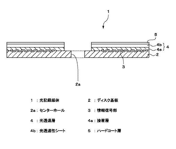
図1は、この発明の一実施形態による光記録媒体1の一構成例を示す断面図である。図1に示すように、この光記録媒体1は、ディスク基板2と、このディスク基板2の一主面に形成された情報信号部3と、この情報信号部3上に形成された光透過層4と、この光透過層4上に形成されたハードコート層5とを備える。
FIG. 1 is a cross-sectional view showing a configuration example of an
この一実施形態による光記録媒体1では、光透過層4の側からレーザ光を情報信号部3に照射することにより、情報信号の記録および/または再生が行われる。例えば、400nm以上410nm以下の範囲の波長を有するレーザ光を、0.84以上0.86以下の範囲の開口数を有する対物レンズにより集光し、光透過層4の側から情報信号部3に照射することにより、情報信号の記録および/または再生が行われる。このような光記録媒体1としては、例えばBlu−ray Disc(登録商標)が挙げられる。なお、以下では、情報信号の記録および/または再生を行うためのレーザ光を照射する側の面を信号面と称する。
In the
ディスク基板2は、中央にセンターホール2aが形成された円環形状を有する。このディスク基板2の情報信号部3が形成される側の一主面には、情報信号の記録および/または再生を行う際に光学スポットを導くための案内溝となる凹凸部が形成されている。この溝を案内としてレーザ光が光記録媒体1上の任意の位置へと移動できる。この溝の形状としては、スパイラル状、同心円状、ピット列等、各種の形状が挙げられる。ディスク基板2の直径は、例えば120mmに選ばれる。ディスク基板2の厚さは、剛性を考慮して選ばれ、好ましくは0.3mm〜1.3mmから選ばれ、より好ましくは0.6mm〜1.3mmから選ばれ、例えば1.1mmに選ばれる。
The
ディスク基板2の材料としては、例えばポリカーボネート系樹脂、ポリオレフィン系樹脂、またはアクリル系樹脂などのプラスチック材料や、ガラスなどが用いられる。なお、コストを考慮した場合には、ディスク基板2の材料として、プラスチック材料を用いることが好ましい。
As a material of the
情報信号部3は、反射膜または記録膜である。反射膜の材料としては、例えば、金属元素、半金属元素、これらの化合物または混合物が挙げられ、より具体的には例えば、Al、Ag、Au、Ni、Cr、Ti、Pd、Co、Si、Ta、W、Mo、Geなどの単体、またはこれらの単体を主成分とする合金が挙げられる。そして、実用性の面を考慮すると、これらのうちのAl系、Ag系、Au系、Si系またはGe系の材料を用いることが好ましい。また、記録膜は、光記録媒体1が追記型または書換可能型であるかに応じて選ばれる。光記録媒体1が追記型の場合には、記録膜としては、例えば、反射膜、有機色素膜をディスク基板2上に順次積層して構成される記録膜が挙げられる。光記録媒体1が書換可能型である場合には、記録膜としては、例えば、反射膜、下層誘電体層、層変化記録膜、上層誘電体層をディスク基板2上に順次積層して構成される記録膜が挙げられる。
The
光透過層4は、平面円環形状を有する光透過性シート(フィルム)4bと、この光透過性シート4bを情報信号部3が形成されたディスク基板2に対して貼り合わせるための接着層4aとから構成される。接着層4aは、例えば紫外線硬化樹脂または感圧性粘着剤(PSA:Pressure Sensitive Adhesive)からなる。光透過層4の厚さは、赤色レーザから青色レーザまで対応することを考慮すると、10μm〜177μmの範囲に設定することが好ましい。
The
光透過性シート4bは、記録および/または再生に用いられるレーザ光に対して、吸収能が低い材料からなることが好ましく、具体的には透過率90パーセント以上の材料からなることが好ましい。光透過性シート4bの材料としては、例えばポリカーボネート樹脂材料、ポリオレフィン系樹脂(例えばゼオネックス(登録商標))が挙げられる。
The
また、この光透過性シート4bの厚さは、好ましくは0.3mm以下に選ばれ、より好ましくは3〜177μmの範囲内から選ばれる。例えば、光透過性シート4bの厚さは、この光透過製シート4bと接着層4aとの合計の厚さが例えば100μmになるように選ばれる。このような薄い光透過層4と、0.85程度の高NA化された対物レンズとを組み合わせることによって、高密度記録を実現することができる。
Further, the thickness of the
ハードコート層5は、光透過層4を保護するための保護層であり、ハードコート剤を硬化してなる。ハードコート剤としては、例えば感光性樹脂を使用できる。感光性樹脂としては、例えば紫外線硬化樹脂、より具体的には溶剤型の紫外線硬化樹脂を使用できる。また、硬度を高めるために有機物により被覆されたコロイダルシリカを含有する紫外線硬化樹脂、または帯電防止性を改善した紫外線硬化樹脂などを用いてもよい。
The
紫外線硬化樹脂は、例えば、単官能または多感能モノマー、重合開始剤および溶剤を少なくとも含有する。なお、必要とする紫外線硬化樹脂の特性に応じて、添加剤、オリゴマーなどを添加するようにしてもよい。 The ultraviolet curable resin contains, for example, at least a monofunctional or multifunctional monomer, a polymerization initiator, and a solvent. In addition, you may make it add an additive, an oligomer, etc. according to the characteristic of the ultraviolet curable resin to require.
モノマーとしては、例えばアクリルモノマー、メタクリルモノマー、スチレン系モノマー、ビニルモノマーなどが挙げられる。重合開始剤としは、例えばケトン系、ベンゾイン系、チオキサン系などの光重合開始剤が挙げられる。ケトン系としたは、例えばアセトフェノン、ベンゾフェノンなどが挙げられる。ベンゾイン系としては、例えばベンゾイン、ベンゾインメチルエーテルなどが挙げられる。チオキサン系としは、例えばチオキサン、2−メチルチオキサンなどが挙げられる。 Examples of the monomer include acrylic monomers, methacrylic monomers, styrene monomers, vinyl monomers, and the like. Examples of the polymerization initiator include ketone-based, benzoin-based, and thioxan-based photopolymerization initiators. Examples of the ketone type include acetophenone and benzophenone. Examples of the benzoin system include benzoin and benzoin methyl ether. Examples of the thioxan series include thioxan and 2-methylthioxan.
アクリルモノマーとしては、例えば以下のものを挙げることができる。側鎖に官能基なしのタイプとしては、例えば、アクリル酸メチル、アクリル酸エチル、アクリル酸ブチル、アクリル酸イソブチル、アクリル酸t−ブチル、アクリル酸ベンジル、シクロヘキシルアクリレート、アクリル酸2−エチルヘキシル、アクリル酸セチル、アクリル酸ラウリル、アクリル酸n−ステアリル、アクリル酸イソボルニル、アクリル酸2−メトキシエチル、アクリル酸3−メトキシブチル、エトキシジエチレングリコールアクリレート、カプロラクトン変性テトラヒドロフルフリルアクリレート、カプロラクトン変性ヒドロキシピバリン酸ネオペンチルグリコールエステルジアクリレート、テトラヒドロフルフリルアクリレート等を挙げることができる。 Examples of the acrylic monomer include the following. Examples of types having no functional group in the side chain include methyl acrylate, ethyl acrylate, butyl acrylate, isobutyl acrylate, t-butyl acrylate, benzyl acrylate, cyclohexyl acrylate, 2-ethylhexyl acrylate, and acrylic acid. Cetyl, lauryl acrylate, n-stearyl acrylate, isobornyl acrylate, 2-methoxyethyl acrylate, 3-methoxybutyl acrylate, ethoxydiethylene glycol acrylate, caprolactone-modified tetrahydrofurfuryl acrylate, caprolactone-modified hydroxypivalic acid neopentyl glycol ester Examples include diacrylate and tetrahydrofurfuryl acrylate.
一分子中に二重結合を複数持つタイプとしては、例えば、エチレングリコールジアクリレート、ジエチレングリコールジアクリレート、1,4−ブタンジオールジアクリレート、1,6−ヘキサンジオールジアクリレート、トリプロピレングリコールジアクリレート、トリメチロールプロパントリアクリレート、トリメチロールプロパンEO変性トリアクリレート、ペンタエリスリトールトリアクリレート、ネオペンチルグリコールヒドロキシピバリン酸エステルジアクリレート、1,9−ノナンジオールアクリレート、ジペンタエリスリトールペンタアクリレート、ジペンタエリスリトールヘキサアクリレート、アクリル変性ジペンタエリスリトールのアクリレート、EO変性ビスフェノールAジアクリレート、ε−カプロラクトン変性ジペンタエリスリトールのアクリレート、2−プロペノイックアシッド[2≡〔1,1−ジメチル−2−〔(1−オキソ−2−プロペニル)オキシ〕エチル〕−5−エチル−1,3−ジオキサン−5−イル]メチルエステル等を挙げることができる。 Examples of the type having a plurality of double bonds in one molecule include ethylene glycol diacrylate, diethylene glycol diacrylate, 1,4-butanediol diacrylate, 1,6-hexanediol diacrylate, tripropylene glycol diacrylate, tripropylene glycol, and the like. Methylolpropane triacrylate, trimethylolpropane EO modified triacrylate, pentaerythritol triacrylate, neopentyl glycol hydroxypivalate ester diacrylate, 1,9-nonanediol acrylate, dipentaerythritol pentaacrylate, dipentaerythritol hexaacrylate, acrylic modification Dipentaerythritol acrylate, EO modified bisphenol A diacrylate, ε-caprolactone modified di Intererythritol acrylate, 2-propenoic acid [2≡ [1,1-dimethyl-2-[(1-oxo-2-propenyl) oxy] ethyl] -5-ethyl-1,3-dioxane-5 Yl] methyl ester and the like.
側鎖に水酸基を有するタイプとしては、例えば、2−ヒドロキシエチルアクリレート、2−ヒドロキシプロピルアクリレート、アクリル酸4−ヒドロキシブチル等を挙げることができる。 Examples of the type having a hydroxyl group in the side chain include 2-hydroxyethyl acrylate, 2-hydroxypropyl acrylate, 4-hydroxybutyl acrylate, and the like.
側鎖に酸性の基を有するタイプとしては、例えば、無水フタル酸−アクリル酸2−ヒドロキシプロピル付加物等を挙げることができる。 Examples of the type having an acidic group in the side chain include phthalic anhydride-acrylic acid 2-hydroxypropyl adduct and the like.
側鎖に塩基性の基を有するタイプとしては、例えば、2−ジメチルアミノエチルアクリレート、2−ジエチルアミノエチルアクリレート等を挙げることができる。 Examples of the type having a basic group in the side chain include 2-dimethylaminoethyl acrylate and 2-diethylaminoethyl acrylate.
側鎖にエポキシ基を有するタイプとしては、例えば、グリシジルアクリレート等を挙げることができる。 Examples of the type having an epoxy group in the side chain include glycidyl acrylate.
側鎖にイオン性の基を有するタイプとしては、例えば、N,N,N−トリメチル−N−(2−ヒドロキシ−3−アクリロイルオキシプロピル)アンモニウムクロライド等を挙げることができる。 Examples of the type having an ionic group in the side chain include N, N, N-trimethyl-N- (2-hydroxy-3-acryloyloxypropyl) ammonium chloride.
アクリルモノマーは、上述の例に限られるものではなく、例えば、N,N−ジメチルアクリルアミド、アクリロニトリル、アクリルアミド、ジメチルアミノプロピルメタアクリルアミド、ダイアセトンアクリルアミド、N,N−ジメチルアミノプロピルアクリルアミド、N,N≡ジメチルアクリルアミドを用いることができる。 The acrylic monomer is not limited to the above-mentioned examples. For example, N, N-dimethylacrylamide, acrylonitrile, acrylamide, dimethylaminopropylmethacrylamide, diacetoneacrylamide, N, N-dimethylaminopropylacrylamide, N, N≡ Dimethylacrylamide can be used.
メタクリルモノマーとしては、例えば、上記アクリルモノマーのアクリル基をメタクリル基に置き換えたものを用いることができる。 As a methacryl monomer, what replaced the acrylic group of the said acrylic monomer with the methacryl group can be used, for example.
スチレン系モノマーとしては、例えば、スチレン、ジビニルベンゼン、p−t−ブトキシスチレン、p−アセトキシスチレン、p−(1−エトキシ)スチレン、2−t−ブトキシ−6−ビニルナフタレン、p−クロロスチレン、p−スチレンスルホン酸ソーダを用いることができる。 Examples of the styrenic monomer include styrene, divinylbenzene, pt-butoxystyrene, p-acetoxystyrene, p- (1-ethoxy) styrene, 2-t-butoxy-6-vinylnaphthalene, p-chlorostyrene, p-Styrene sulfonic acid soda can be used.
また、酢酸ビニル、塩化ビニル、4−ヒドロキシブチルビニルエーテル、ジエチンエチレングリコールモノビニルエーテル、N−ビニル−2−ピロリドンなどを使用することも可能である。 Moreover, it is also possible to use vinyl acetate, vinyl chloride, 4-hydroxybutyl vinyl ether, dietine ethylene glycol monovinyl ether, N-vinyl-2-pyrrolidone, and the like.
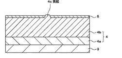
図2は、光透過層4表面に突起4cを有する光記録媒体1の模式的断面図である。このハードコート層5の厚さは、光透過層4の信号面にある突起4cの高さ以下であり、好ましくは突起高さの4割以下である。実際には、光透過層4の表面には無数の微小突起4cがあるため、ハードコート層5の厚さは例えば以下のようにして規定する。
FIG. 2 is a schematic cross-sectional view of the
まず、複数の光記録媒体1について、光透過層4にある突起4cを予め測定し、この測定結果に基づき、突起4cの高さの平均値を算出する。そして、この平均値に基づき、ハードコート層5の厚さを規定する。すなわち、ハードコート層5の厚さを、突起4cの高さの平均値以下、好ましくはこの平均値の4割以下に規定する。ハードコート層5の厚さを突起4cの高さの平均値以下にすることにより、記録再生時のエラーの発生を低減することができる。さらに、ハードコート層5の厚さを平均値の4割以下にすることにより、記録再生時のエラーの発生をより低減することができる。
First, with respect to the plurality of
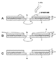
次に、この発明の一実施形態による光記録媒体1の製造方法の一例について説明する。図3および図4は、この一実施形態による光記録媒体1の製造方法を説明するための断面図である。
Next, an example of a method for manufacturing the
まず、図3Aに示すように、例えば射出成形法により、一主面に凹凸が形成されたディスク基板2を作製する。次に、図3Bに示すように、ディスク基板2の凹凸が形成された一主面に、情報信号部3を形成する。具体的には、例えば、最終製品としての光記録媒体1が再生専用型である場合には、ディスク基板2の凹凸が形成された一主面に、例えば真空蒸着法あるいはスパッタリング法などにより、Al、Al合金またはAg合金などからなる反射層を成膜する。
First, as shown in FIG. 3A, a
次に、ディスク基板2の情報信号部3が形成された一主面に、接着層4aを介して光透過性シート4bを貼り合わせる。これにより、図3cに示すように、ディスク基板2の情報信号部3が形成された一主面に、光透過層4が形成される。
Next, a
次に、光透過層4が上になるようにして、スピンコータ(図示省略)上に光記録媒体1を載置する。この際、光記録媒体1のセンターホール2aを、スピンコータのセンターピンに嵌め合わせるようにする。
Next, the
次に、図4Aに示すように、例えば100〜200rpmの範囲の回転数で光記録媒体を穏やかに回転させた状態で、光記録媒体1の内周部から外周部に向かって、信号面の上方に位置するノズル7から紫外線硬化樹脂6を滴下する。例えば、内周部から外周部に向かって2/3程度の領域に、紫外線硬化樹脂6を塗布する。
Next, as shown in FIG. 4A, in a state where the optical recording medium is gently rotated at a rotational speed in the range of, for example, 100 to 200 rpm, the signal surface of the
次に、図4Bに示すように、例えば3000〜5000rpmの範囲の回転数で、1〜3秒間、光記録媒体1を高速に回転させて、紫外線硬化樹脂6を光記録媒体1全面に均一に行き渡せるようにして、余分な紫外線硬化樹脂6を振り切る。
Next, as shown in FIG. 4B, the
その後、光記録媒体1の信号面に紫外線を照射して紫外線硬化樹脂6を硬化させる。紫外線の光源としては、例えば紫外線ランプ(UVランプ)を使用できる。以上により、図4Cに示すように、ハードコート層5を信号面に有する光記録媒体1を得ることができる。
Thereafter, the ultraviolet
なお、ハードコート層5の厚さは、例えば、回転数、振り切り時間、紫外線硬化樹脂の固形分の濃度を適宜制御することにより調整できる。具体的には、例えば、回転数、振り切り時間を一定として、紫外線硬化樹脂の固形分の濃度を適宜調整することにより、所望とするハードコート層5の厚さを得ることができる。
In addition, the thickness of the
この発明の一実施形態によれば以下の効果を得ることができる。
ハードコート層5の厚さを信号面に形成された突起4cの高さ以下とするので、突起4cをエンハンスすることなく、ハードコート層5を信号面に形成できる。よって、信号面の突起4cを埋め込むようにハードコート層5を厚く形成することなく、ハードコート層5の形成に伴うエラーレートの増加を抑制することができる。
According to one embodiment of the present invention, the following effects can be obtained.
Since the thickness of the
以下、実施例により本発明を具体的に説明するが、本発明はこれらの実施例のみに限定されるものではない。 EXAMPLES Hereinafter, although an Example demonstrates this invention concretely, this invention is not limited only to these Examples.
(1)突起の平均高さの算出
まず、複数のサンプルを作製して光透過層4の表面に形成された突起4cの高さの平均値を算出した。
(1) Calculation of Average Height of Protrusions First, a plurality of samples were prepared, and the average height of the protrusions 4c formed on the surface of the
サンプル1〜8
まず、射出成形法により、一主面に凹凸が形成されたディスク基板2を作製した。次に、ディスク基板2の凹凸が形成された一主面に、情報信号部3を形成した。次に、流延法により作製された帯状の光透過性シートを打ち抜いて円盤状の光透過性シート4bを作製した。次に、ディスク基板2の情報信号部3が形成された一主面に、接着層4aを介して光透過性シート4bを貼り合わせた。以上により、サンプル1が得られた。
そして、サンプル1とすべて同様にしてサンプル2〜8を得た。
Samples 1-8
First, a
次に、上述のようにして作製されたサンプル1〜8の光透過層4の表面にある突起4cの高さを、段差・表面粗さ・微細形状測定装置(ケーエルエー・テンコール(KLA−Tencor)社)を用いて以下のようにして測定した。すなわち、各サンプルにつき、突起1個を特性し、突起のトップ(頂点)が入る範囲、縦、横、200μmの範囲を5μmピッチで操作させ、そこで得られたデータのうち、最も高い高さを各サンプルの測定高さとした。
Next, the height of the protrusion 4c on the surface of the
そして、測定された突起4cの高さに基づきサンプル1〜8の突起4cの高さの平均値を算出した。なお、平均値の算出は、サンプル1〜8の突起4cの高さを加算し、サンプル数で割ることにより算出した。表1に、サンプル1〜8における突起4cの高さの測定値および突起4cの高さの平均値を示す。
And the average value of the height of the processus | protrusion 4c of the samples 1-8 was computed based on the measured height of the processus | protrusion 4c. The average value was calculated by adding the heights of the protrusions 4c of the
(2)バーストエラー個数の検討
次に、上述のようにして算出された突起4cの高さの平均値に基づき、実施例1〜3および比較例1〜5の光記録媒体1を作製した。表2に、実施例1〜3および比較例1〜5のハードコート層5の膜厚と、固形分の含有率とを示す。
(2) Examination of the number of burst errors Next, the
実施例1
まず、光透過層4を形成するまでの工程はサンプル1とすべて同様にして光記録媒体1を得た。そして、光記録媒体1全面のエラーレートを測定した。
Example 1
First, the
次に、図示を省略したスピンコータの所定位置に、上述のようにして得られた光記録媒体1を載置した。そして、回転数200rpmで光記録媒体1を穏やかに回転させた状態で、光記録媒体1の内周部から外周部に向かって、信号面の上方に位置するノズル7から紫外線硬化樹脂を滴下した。
Next, the
ここで、紫外線硬化樹脂としては、固形分の含有率が3重量%となるように、市販の紫外線硬化樹脂を溶剤により希釈したものを用いた。なお、市販の紫外線硬化樹脂は、固形分40重量%と、溶剤60重量%とからなり、この固形分は、高分子原材料であるアクリルモノマーを主成分とする。 Here, as the ultraviolet curable resin, a commercially available ultraviolet curable resin diluted with a solvent was used so that the solid content was 3% by weight. The commercially available ultraviolet curable resin comprises a solid content of 40% by weight and a solvent of 60% by weight, and the solid content is mainly composed of an acrylic monomer as a polymer raw material.
次に、回転数3000rpmで1秒間、光記録媒体1を高速で回転させて、紫外線硬化樹脂を光記録媒体1全面に均一に行き渡らせるようにして、余分な紫外線硬化樹脂を振り切った。これにより、光透過層4上に紫外線硬化樹脂が均一に塗布された。
Next, the
次に、紫外線を照射して紫外線硬化樹脂を硬化させて、厚さ0.15um有するハードコート層5を形成した。そして、光記録媒体1全面のエラーレートを測定した。その後、ハードコート層5の形成前に比べてエラーレートが増加している箇所の個数を光記録媒体1全面において求めた。
Next, the
実施例2
固形分の含有率が10重量%となるように市販の紫外線硬化樹脂を希釈して、0.4umのハードコート層5を形成する以外はすべて実施例1と同様にして光記録媒体1を得た。また、実施例1と同様にして、ハードコート層5の形成前後において光記録媒体1全面のエラーレートを測定した。そして、実施例1と同様にして、ハードコート層5の形成前に比べてエラーレートが増加している箇所の個数を光記録媒体1全面において求めた。
Example 2
An
実施例3
固形分の含有率が20重量%となるように市販の紫外線硬化樹脂を希釈して、0.63umのハードコート層5を形成する以外はすべて実施例1と同様にして光記録媒体1を得た。また、実施例1と同様にして、ハードコート層5の形成前後において光記録媒体1全面のエラーレートを測定した。そして、実施例1と同様にして、ハードコート層5の形成前に比べてエラーレートが増加している箇所の個数を光記録媒体1全面において求めた。
Example 3
An
比較例1
固形分の含有率が40重量%となるように市販の紫外線硬化樹脂を希釈して、1.5umのハードコート層5を形成する以外はすべて実施例1と同様にして光記録媒体1を得た。また、実施例1と同様にして、ハードコート層5の形成前後において光記録媒体1全面のエラーレートを測定した。そして、実施例1と同様にして、ハードコート層5の形成前に比べてエラーレートが増加している箇所の個数を光記録媒体1全面において求めた。
Comparative Example 1
An
比較例2
固形分の含有率が60重量%となるように市販の紫外線硬化樹脂を希釈して、2.0umのハードコート層5を形成する以外はすべて実施例1と同様にして光記録媒体1を得た。また、実施例1と同様にして、ハードコート層5の形成前後において光記録媒体1全面のエラーレートを測定した。そして、実施例1と同様にして、ハードコート層5の形成前に比べてエラーレートが増加している箇所の個数を光記録媒体1全面において求めた。
Comparative Example 2
An
比較例3
固形分の含有率が40重量%となるように市販の紫外線硬化樹脂を希釈して、4.1umのハードコート層5を形成する以外はすべて実施例1と同様にして光記録媒体1を得た。また、実施例1と同様にして、ハードコート層5の形成前後において光記録媒体1全面のエラーレートを測定した。そして、実施例1と同様にして、ハードコート層5の形成前に比べてエラーレートが増加している箇所の個数を光記録媒体1全面において求めた。なお、市販の紫外線硬化樹脂としては、実施例1と異なるものを用いた。
Comparative Example 3
An
比較例4
固形分の含有率が50重量%となるように市販の紫外線硬化樹脂を希釈して、5.6umのハードコート層5を形成する以外はすべて実施例1と同様にして光記録媒体1を得た。また、実施例1と同様にして、ハードコート層5の形成前後において光記録媒体1全面のエラーレートを測定した。そして、比較例3と同様にして、ハードコート層5の形成前に比べてエラーレートが増加している箇所の個数を光記録媒体1全面において求めた。
Comparative Example 4
An
比較例5
固形分の含有率が60重量%となるように市販の紫外線硬化樹脂を希釈して、6.1umのハードコート層5を形成する以外はすべて実施例1と同様にして光記録媒体1を得た。また、実施例1と同様にして、ハードコート層5の形成前後において光記録媒体1全面のエラーレートを測定した。そして、比較例3と同様にして、ハードコート層5の形成前に比べてエラーレートが増加している箇所の個数を光記録媒体1全面において求めた。
Comparative Example 5
An
なお、実施例1〜3および比較例1〜5においてハードコート層5の膜厚の測定は、以下のようにして行った。すなわち、キーエース(株)レーザフォーカス変位計(コントローラLT−8100、ヘッドLT−8010、カメラユニットLT−V201)を使用して、ディスク半径22〜56mmの範囲を、細かくサンプリングしたデータの平均値(具体的には、ディスク半径22〜56mmについて2mmステップで3度おきにサンプリングしたデータの平均値)を膜厚とした。
In Examples 1 to 3 and Comparative Examples 1 to 5, the thickness of the
図5は、実施例1〜3および比較例1〜5のハードコート層5の厚みとバーストエラーの個数との関係を示すグラフである。なお、光透過層4の表面にて突起4cがハードコート層5によりエンハンスされてしまった箇所ではエラーレートが増加するため、エラーレートが増加する箇所で生じるエラーをバーストエラーとしてカウントした。
FIG. 5 is a graph showing the relationship between the thickness of the
図5から以下のことが分かる。すなわち、ハードコート層5の厚さを、突起4cの平均高さ以下、すなわち1.1um以下にすることにより、バーストエラー個数を低減できることが分かる。また、ハードコート層5の厚さを、突起4cの平均高さの4割以下にすることにより、バーストエラー個数をほぼゼロにできることが分かる。また、固形分の含有率を、3〜10重量%、すなわち10重量%以下にすることにより、バーストエラー個数をほぼゼロにできることが分かる。
The following can be seen from FIG. That is, it can be seen that the number of burst errors can be reduced by setting the thickness of the
(3)反り変化量の検討
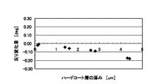
次に、ハードコート層形成前後における光記録媒体1の反り変化量を検討した。表3に、実施例4,5および比較例6〜11のハードコート層5の膜厚と、固形分の含有率とを示す。
(3) Examination of warpage change amount Next, the warpage change amount of the
実施例4
まず、光透過層4を形成するまでの工程は実施例1とすべて同様にして光記録媒体1を得た。そして、光記録媒体1の反り量を、変化量の一番大きい外周部において測定した。
Example 4
First, the
次に、実施例1と同様にして、固形分の含有率が3重量%となるように市販の紫外線硬化樹脂を希釈して、0.15umのハードコート層5を有する光記録媒体1を得た。そして、光記録媒体1の反り量を、変化量の一番大きい外周部において測定した。その後、上述のようにして測定された反り量に基づき、ハードコート層形成前後における反りの変化量を算出した。
Next, in the same manner as in Example 1, a commercially available ultraviolet curable resin was diluted so that the solid content was 3% by weight to obtain an
実施例5
実施例4とすべて同様にして光記録媒体1を得た。また、実施例4と同様にして、ハードコート層5形成前後における反りの変化量を測定した。
Example 5
The
比較例6
固形分の含有率が40重量%となるように市販の紫外線硬化樹脂を希釈して、1.4umのハードコート層5を形成する以外はすべて実施例1と同様にして光記録媒体1を得た。また、実施例4と同様にして、ハードコート層5形成前後における反りの変化量を測定した。
Comparative Example 6
An
比較例7
固形分の含有率が40重量%となるように市販の紫外線硬化樹脂を希釈して、1.6umのハードコート層5を形成する以外はすべて実施例1と同様にして光記録媒体1を得た。また、実施例4と同様にして、ハードコート層5形成前後における光記録媒体1の反りを測定した。
Comparative Example 7
An
比較例8
固形分の含有率が30重量%となるように市販の紫外線硬化樹脂を希釈して、2.6umのハードコート層5を形成する以外はすべて比較例3と同様にして光記録媒体1を得た。また、実施例4と同様にして、ハードコート層5形成前後における光記録媒体1の反りを測定した。
Comparative Example 8
An
比較例9
固形分の含有率が30重量%となるように市販の紫外線硬化樹脂を希釈して、2.8umのハードコート層5を形成する以外はすべて比較例3と同様にして光記録媒体1を得た。また、実施例4と同様にして、ハードコート層5形成前後における光記録媒体1の反りを測定した。
Comparative Example 9
An
比較例10
固形分の含有率が40重量%となるように市販の紫外線硬化樹脂を希釈して、4.3umのハードコート層5を形成する以外はすべて比較例3と同様にして光記録媒体1を得た。また、実施例4と同様にして、ハードコート層5形成前後における光記録媒体1の反りを測定した。
Comparative Example 10
An
比較例11
固形分の含有率が40重量%となるように市販の紫外線硬化樹脂を希釈して、4.4umのハードコート層5を形成する以外はすべて比較例3と同様にして光記録媒体1を得た。また、実施例4と同様にして、ハードコート層5形成前後における光記録媒体1の反りを測定した。
Comparative Example 11
The
なお、実施例4,5および比較例6〜11におけるハードコート層5の膜厚の測定は、上述の実施例1〜3および比較例1〜5と同様にして行った。
In addition, the measurement of the film thickness of the hard-
図6は、実施例4,5および比較例6〜11のハードコート層形成前後における反りの変化量を示すグラフである。図6から以下のことが分かる。すなわち、ハードコート層5の厚さを、突起4cの高さの平均値以下、すなわち1.1umにすることにより、ハードコート層5形成前後における光記録媒体1の反りの変化量を抑制でき、反りの変化量をほぼゼロの抑えることができることが分かる。
FIG. 6 is a graph showing the amount of change in warpage before and after the hard coat layer formation in Examples 4 and 5 and Comparative Examples 6 to 11. The following can be seen from FIG. That is, by setting the thickness of the
(4)外部衝撃試験
次に、光記録媒体1に対して外部衝撃を与える試験を行った。まず、以下に示すようにして、外部衝撃試験をするための実施例6および比較例12の光記録媒体1を作製した。
(4) External Impact Test Next, a test for applying an external impact to the
実施例6
固形分の含有率が3重量%となるように市販の紫外線硬化樹脂を希釈して、0.15umのハードコート層5を形成する以外はすべて実施例1と同様にして光記録媒体1を得た。
Example 6
An
比較例12
ハードコート層5の形成を省略する以外はすべて実施例1と同様にして光記録媒体1を得た。
Comparative Example 12
An
次に、上述のようにして得られた実施例6および比較例12光記録媒体1に対して以下の外部衝撃試験を行った。まず、光記録媒体1をポータブル型のドライブに装着した状態でドライブを転倒させ、ピックアップ部を故意に光記録媒体1の表面に衝突させた。そして、光記録媒体1の表面を目視し、表面に付着物および傷があるか否かを観察した。表4に、実施例6および比較例12の目視による観察結果を示す。
Next, the following external impact test was performed on the
実施例6では、表面に傷・付着物は観察されなかった。これに対して、ハードコート層5を表面に形成していない比較例12では、表面に傷や付着物が観察された。したがって、実施例6の光記録媒体1は、外部からの衝撃に強く、傷が付きにくいことが分かる。
In Example 6, no scratches or deposits were observed on the surface. In contrast, in Comparative Example 12 in which the
(5)クリーニング性の評価
次に、光記録媒体1の信号面におけるクリーニング性を評価した。まず、以下に示すようにして、クリーニング性を評価するための実施例7および比較例13を作製した。
(5) Evaluation of cleaning property Next, the cleaning property on the signal surface of the
実施例7
固形分の含有率が3重量%となるように市販の紫外線硬化樹脂を希釈して、0.15umのハードコート層5を形成する以外はすべて実施例1と同様にして光記録媒体1を得た。
Example 7
An
比較例13
ハードコート層5の形成を省略する以外はすべて実施例1と同様にして光記録媒体1を得た。
Comparative Example 13
An
次に、上述のようにして得られた実施例7および比較例13の光記録媒体1の表面のクリーニング前後での所定箇所のエラーを測定してその増加分を算出した。なお、クリーニングは、エタノールをしみ込ませた綿棒で200回前後拭いて行った。クリーニング領域は、およそ30mm×5mmとした。表5に、クリーニング性の確認結果を示す。
Next, the error at a predetermined location before and after cleaning the surface of the
実施例7では、エラー増加箇所が極めて少なく、データの読み書きに問題がないのに対して、比較例13では、細かい傷が表面に沢山付き、エラー箇所が大きく増加し、データの読み書きは困難であった。 In Example 7, there are very few error increasing parts and there is no problem in reading and writing data. In Comparative Example 13, many fine scratches are on the surface, the number of error parts is greatly increased, and reading and writing of data is difficult. there were.
塵埃試験
次に、光記録媒体1の記録面に対する塵や埃などの付着し易さを評価するための塵埃試験を行った。まず、以下のようにして、塵埃試験をするための実施例8および比較例14の光記録媒体1を作製した。
Dust Test Next, a dust test was performed to evaluate the ease of adhesion of dust and dirt to the recording surface of the
実施例8
固形分の含有率が3重量%となるように市販の紫外線硬化樹脂を希釈して、0.15umのハードコート層5を形成する以外はすべて実施例1と同様にして光記録媒体1を得た。
Example 8
An
比較例14
ハードコート層5の形成を省略する以外はすべて実施例1と同様にして光記録媒体1を得た。
Comparative Example 14
An
次に、実施例8および比較例14の光記録媒体1を塵埃試験機に投入し、光記録媒体1の表面に付着したダストの量を目視にて確認した。なお、この試験は、通常環境のダスト状態に比べてかなり加速された厳しい条件で行ったものである。表6に、実施例8および比較例14の光記録媒体1の塵埃試験の結果を示す。
Next, the
実施例8では、表面へのダスト付着量が比較例14に比べて明らかに少ないことが分かった。すなわち、実施例8では、比較例14に比べて埃やダストが付着しにくいことが分かった。 In Example 8, it was found that the amount of dust attached to the surface was clearly smaller than that in Comparative Example 14. That is, in Example 8, it turned out that dust and dust do not adhere easily compared with Comparative Example 14.
以上、この発明の一実施形態について具体的に説明したが、この発明は、上述の一実施形態に限定されるものではなく、この発明の技術的思想に基づく各種の変形が可能である。 The embodiment of the present invention has been specifically described above, but the present invention is not limited to the above-described embodiment, and various modifications based on the technical idea of the present invention are possible.
例えば、上述の一実施形態において挙げた数値はあくまでも例に過ぎず、必要に応じてこれと異なる数値を用いてもよい。 For example, the numerical values given in the above-described embodiment are merely examples, and different numerical values may be used as necessary.
また、上述の一実施形態では、光透過層4側から光を照射して情報信号の記録および/または再生が行われる光記録媒体1に対してこの発明を適用した例について示したが、この発明はこのような構成を有する光記録媒体に限定されるものではない。例えば、基板が光透過性を有し、基板側から光を照射して情報信号の記録および/または再生が行われる光記録媒体(例えば、CD(Compact Disc))、基板を貼り合わせて構成される光記録媒体(例えば、DVD(Digital Versatile Disc))などにも、本発明は適用可能である。
In the above-described embodiment, the example in which the present invention is applied to the
また、上述の一実施形態では、1層の情報信号部3を有する光記録媒体1に対してこの発明を適用した例について示したが、2層以上の情報信号部3を有する光記録媒体1に対してこの発明を適用してもよい。
In the above-described embodiment, the example in which the present invention is applied to the
また、上述の一実施形態では、光透過層4が、接着層4aと光透過性シート4bとから構成される場合を例として示したが、光透過層4を紫外線硬化樹脂のみを用いて構成するようにしてもよい。この場合の光透過層4の形成方法としては、例えばスピンコート法が挙げられる。
Further, in the above-described embodiment, the case where the
また、上述の一実施形態では、ハードコート層5を光記録媒体1上に形成する例について示したが、ハードコート層5を形成する対象はこれに限られるものではない。ハードコート層5を形成する対象としては、例えば、光学レンズ、光学フィルタ、反射防止膜、液晶ディスプレー、プラズマディスプレー、タッチパネルなどが挙げられる。
In the above-described embodiment, an example in which the
1・・・光記録媒体、2・・・ディスク基板、3・・・情報信号部、4a・・・接着層、4b・・・光透過製シート、5・・・ハードコート層
DESCRIPTION OF
Claims (10)
上記ハードコート層の厚さが、上記信号面にある突起の高さ以下であることを特徴とする光記録媒体。 In an optical recording medium provided with a hard coat layer on a signal surface irradiated with light for recording and / or reproducing information signals,
An optical recording medium, wherein the thickness of the hard coat layer is equal to or less than the height of the protrusion on the signal surface.
情報信号の記録および/または再生をするための光が上記光透過層側から上記情報信号部に照射されることを特徴とする請求項1記載の光記録媒体。 An information signal part and a light transmission layer are sequentially laminated on the disk substrate,
2. The optical recording medium according to claim 1, wherein light for recording and / or reproducing information signals is applied to the information signal portion from the light transmission layer side.
上記信号面に塗布された樹脂を硬化してハードコート層を形成する工程と
を備えた光記録媒体の製造方法において、
上記ハードコート層の厚さが上記信号面にある突起の高さ以下となるように、上記樹脂を上記信号面に塗布することを特徴とする光記録媒体の製造方法。 Applying a resin to a signal surface irradiated with light for recording and / or reproducing information signals;
A method of manufacturing an optical recording medium comprising: a step of curing a resin applied to the signal surface to form a hard coat layer;
A method for producing an optical recording medium, wherein the resin is applied to the signal surface such that the thickness of the hard coat layer is equal to or less than the height of the protrusion on the signal surface.
Priority Applications (1)
| Application Number | Priority Date | Filing Date | Title |
|---|---|---|---|
| JP2004109425A JP2005293757A (en) | 2004-04-01 | 2004-04-01 | Optical recording medium and manufacturing method thereof |
Applications Claiming Priority (1)
| Application Number | Priority Date | Filing Date | Title |
|---|---|---|---|
| JP2004109425A JP2005293757A (en) | 2004-04-01 | 2004-04-01 | Optical recording medium and manufacturing method thereof |
Publications (1)
| Publication Number | Publication Date |
|---|---|
| JP2005293757A true JP2005293757A (en) | 2005-10-20 |
Family
ID=35326518
Family Applications (1)
| Application Number | Title | Priority Date | Filing Date |
|---|---|---|---|
| JP2004109425A Pending JP2005293757A (en) | 2004-04-01 | 2004-04-01 | Optical recording medium and manufacturing method thereof |
Country Status (1)
| Country | Link |
|---|---|
| JP (1) | JP2005293757A (en) |
-
2004
- 2004-04-01 JP JP2004109425A patent/JP2005293757A/en active Pending
Similar Documents
| Publication | Publication Date | Title |
|---|---|---|
| JP4618326B2 (en) | Optical information medium and recording or reproducing method thereof | |
| JP2005112900A (en) | Hard coating composition and light information medium using the same | |
| US7851018B2 (en) | Method of manufacturing optical information recording medium | |
| CN1656548A (en) | Method of manufacturing an optical storage medium and optical storage medium | |
| JP4496766B2 (en) | Method for forming protective layer and method for manufacturing optical information medium | |
| US20100255347A1 (en) | Information recording medium and method for manufacturing same | |
| JP2005293757A (en) | Optical recording medium and manufacturing method thereof | |
| JP4150514B2 (en) | Optical information medium | |
| JP3955867B2 (en) | Manufacturing method of optical information recording medium | |
| WO2008041526A1 (en) | Method and apparatus for manufacturing optical recording medium | |
| CN1331137C (en) | Optical disk and method for manufacturing the same | |
| US8426004B2 (en) | Multilayer information recording medium manufacturing method, multilayer information recording medium manufacturing apparatus, and multilayer information recording medium | |
| JP2008287883A (en) | Optical information medium | |
| JP4715657B2 (en) | Optical disk medium and optical disk medium manufacturing method | |
| JP2000339761A (en) | Optical information medium and method for manufacturing the same | |
| JP4185496B2 (en) | Manufacturing method of optical information medium | |
| WO2007058309A2 (en) | Method and apparatus for producing optical recording medium | |
| JP4656013B2 (en) | Manufacturing method of optical disk medium | |
| JP4794116B2 (en) | Optical information medium | |
| JP2002260276A (en) | Optical information media | |
| WO2004079733A1 (en) | Method of testing optical information medium | |
| JP2007512653A (en) | Equipment for optical disk spin coating | |
| JP2000195102A (en) | Optical information carrier | |
| KR20010069012A (en) | optical disk and method for protecting scratch of the same | |
| KR20040008113A (en) | Optical storage medium |
Legal Events
| Date | Code | Title | Description |
|---|---|---|---|
| RD04 | Notification of resignation of power of attorney |
Free format text: JAPANESE INTERMEDIATE CODE: A7424 Effective date: 20060208 |