JP2005293719A - Disk unit - Google Patents
Disk unit Download PDFInfo
- Publication number
- JP2005293719A JP2005293719A JP2004107649A JP2004107649A JP2005293719A JP 2005293719 A JP2005293719 A JP 2005293719A JP 2004107649 A JP2004107649 A JP 2004107649A JP 2004107649 A JP2004107649 A JP 2004107649A JP 2005293719 A JP2005293719 A JP 2005293719A
- Authority
- JP
- Japan
- Prior art keywords
- voice coil
- head actuator
- support frame
- outer peripheral
- peripheral portion
- Prior art date
- Legal status (The legal status is an assumption and is not a legal conclusion. Google has not performed a legal analysis and makes no representation as to the accuracy of the status listed.)
- Withdrawn
Links
Images
Classifications
-
- G—PHYSICS
- G11—INFORMATION STORAGE
- G11B—INFORMATION STORAGE BASED ON RELATIVE MOVEMENT BETWEEN RECORD CARRIER AND TRANSDUCER
- G11B5/00—Recording by magnetisation or demagnetisation of a record carrier; Reproducing by magnetic means; Record carriers therefor
- G11B5/48—Disposition or mounting of heads or head supports relative to record carriers ; arrangements of heads, e.g. for scanning the record carrier to increase the relative speed
- G11B5/54—Disposition or mounting of heads or head supports relative to record carriers ; arrangements of heads, e.g. for scanning the record carrier to increase the relative speed with provision for moving the head into or out of its operative position or across tracks
- G11B5/55—Track change, selection or acquisition by displacement of the head
- G11B5/5521—Track change, selection or acquisition by displacement of the head across disk tracks
- G11B5/5569—Track change, selection or acquisition by displacement of the head across disk tracks details of specially adapted mobile parts, e.g. electromechanical control devices
-
- G—PHYSICS
- G11—INFORMATION STORAGE
- G11B—INFORMATION STORAGE BASED ON RELATIVE MOVEMENT BETWEEN RECORD CARRIER AND TRANSDUCER
- G11B5/00—Recording by magnetisation or demagnetisation of a record carrier; Reproducing by magnetic means; Record carriers therefor
- G11B5/48—Disposition or mounting of heads or head supports relative to record carriers ; arrangements of heads, e.g. for scanning the record carrier to increase the relative speed
- G11B5/4806—Disposition or mounting of heads or head supports relative to record carriers ; arrangements of heads, e.g. for scanning the record carrier to increase the relative speed specially adapted for disk drive assemblies, e.g. assembly prior to operation, hard or flexible disk drives
- G11B5/4813—Mounting or aligning of arm assemblies, e.g. actuator arm supported by bearings, multiple arm assemblies, arm stacks or multiple heads on single arm
Landscapes
- Moving Of Heads (AREA)
Abstract
【課題】製造が容易であるとともに、剛性が高くかつアクチュエータを効率良く駆動することが可能なディスク装置を提供する。
【解決手段】 ディスク装置のヘッドアクチュエータは、軸受部から延出しているとともに金属で形成された支持フレームを有している。ボイスコイルモータのボイスコイル36は、ヘッドアクチュエータの回転軸とほぼ平行に延びた巻回中心軸を有し、支持フレーム間に配置されている。ボイスコイルの外周部は、支持フレームに対向した対向外周部36aと、軸受部に対して最外周に位置しているとともに外部に露出した露出外周部36bとを有している。ボイスコイルは、対向外周部と支持フレームと間にモールド成形された樹脂45により支持フレームに固定されて、ボイスコイルのリード線46は、モールド成形された樹脂48により覆われヘッドアクチュエータの所定位置に固定されている。
【選択図】 図5A disk device that is easy to manufacture, has high rigidity, and can efficiently drive an actuator.
A head actuator of a disk device has a support frame that extends from a bearing portion and is made of metal. The voice coil 36 of the voice coil motor has a winding center axis extending substantially parallel to the rotation axis of the head actuator, and is disposed between the support frames. The outer peripheral portion of the voice coil has an opposing outer peripheral portion 36a facing the support frame, and an exposed outer peripheral portion 36b that is located on the outermost periphery with respect to the bearing portion and exposed to the outside. The voice coil is fixed to the support frame by a resin 45 molded between the opposed outer peripheral portion and the support frame, and the lead wire 46 of the voice coil is covered by the molded resin 48 and is placed at a predetermined position of the head actuator. It is fixed.
[Selection] Figure 5
Description
この発明は、ディスク状の記録媒体を備えたディスク装置に関する。 The present invention relates to a disk device provided with a disk-shaped recording medium.
近年、コンピュータの外部記録装置や画像記録装置として磁気ディスク装置、光ディスク装置などのディスク装置が広く用いられている。
ディスク装置として、例えば、磁気ディスク装置は、一般に、上面の開口した矩形箱状のケースと、複数のねじによりケースにねじ止めされてケースの上面開口を閉塞したトップカバーと、を有している。ケース内には、磁気記録媒体としての磁気ディスク、この磁気ディスクを支持および回転させる駆動手段としてのスピンドルモータ、磁気ディスクに対して情報の書き込み、読み出しを行なう複数の磁気ヘッド、これらの磁気ヘッドを磁気ディスクに対して移動自在に支持したヘッドアクチュエータ、ヘッドアクチュエータを回動および位置決めするボイスコイルモータ、ヘッドIC等を有する基板ユニット等が収納されている。
In recent years, disk devices such as magnetic disk devices and optical disk devices have been widely used as external recording devices and image recording devices for computers.
As a disk device, for example, a magnetic disk device generally has a rectangular box-shaped case with an open top surface, and a top cover that is screwed to the case with a plurality of screws to close the top surface opening of the case. . The case includes a magnetic disk as a magnetic recording medium, a spindle motor as a driving means for supporting and rotating the magnetic disk, a plurality of magnetic heads for writing and reading information on the magnetic disk, and these magnetic heads. A head actuator movably supported with respect to the magnetic disk, a voice coil motor for rotating and positioning the head actuator, a substrate unit having a head IC, and the like are accommodated.
ボイスコイルモータは、ヘッドアクチュエータの端部に設けられたボイスコイルと、ケースに固定されボイスコイルと対向した磁石およびヨークを有している。そして、ボイスコイルに通電することにより発生した磁界と磁石との磁界との相互作用により回転力を発生し、ヘッドアクチュエータを回動させる。 The voice coil motor has a voice coil provided at the end of the head actuator, and a magnet and a yoke fixed to the case and facing the voice coil. Then, a rotational force is generated by the interaction between the magnetic field generated by energizing the voice coil and the magnetic field of the magnet, and the head actuator is rotated.
ヘッドアクチュエータに対するボイスコイルの固定構造としては、ヘッドアクチュエータから延出した金属フレームに接着剤によってボイルコイルを固定した構造(例えば、特許文献1)、およびボイスコイル全体を樹脂モールドにより覆い、アクチュエータと一体的に形成した構造(例えば、特許文献2)が提供されている。
上述した前者の接着剤による固定構造では、ボイスコイル接着表面の形状のバラツキに起因して、接着強度がバラツキ易い。従って、ボイスコイルの接着強度を一定に保つために、接着剤の充填量や粘度等を非常に気をつける必要がある。また、アクチュエータ組立時、コイル端子をアクチュエータ側の端子へ接続する際、ボイスコイルの接続用ワイヤーをフォーミングする必要がある。更に、この際、接続用ワイヤーの動きを抑える目的で、接続ワイヤーにも接着剤を塗布する場合がある。従って、前者の固定構造は、組立作用が面倒であり、製造効率を上げることが難しい。 In the above-described fixing structure using the adhesive, the adhesive strength tends to vary due to variations in the shape of the voice coil bonding surface. Therefore, in order to keep the adhesive strength of the voice coil constant, it is necessary to pay close attention to the filling amount and viscosity of the adhesive. In addition, when connecting the coil terminal to the terminal on the actuator side when assembling the actuator, it is necessary to form a connection wire for the voice coil. Furthermore, in this case, an adhesive may be applied to the connection wire for the purpose of suppressing the movement of the connection wire. Therefore, the former fixing structure is troublesome in assembling operation, and it is difficult to increase the manufacturing efficiency.
一方、後者の固定構造の場合、接着剤の管理やコイルワイヤーのフォーミングは、モールドの成形時に完了しているため必要としない。しかし、その構造上、モールドがコイル外周全体を一律に覆う形となるため、前者の接着構造と比較して、そのモールドの厚み分だけボイスコイル有効線長が短くなってしまう。更に、ボイスコイルを保持する部分は樹脂で形成されているため、前者の金属フレームを用いた構造に比較して、コイルアッセンブリ全体の剛性が低くなってしまう。近年の高容量HDDにおいては、サーボサンプリング周波数が高くなってきており、コイルアッセンブリの共振周波数を上昇させる必要がある。しかし、上記のようにコイルアッセンブリ全体の剛性が低い場合には、共振周波数を充分に上げることが難しい。 On the other hand, in the case of the latter fixing structure, the management of the adhesive and the forming of the coil wire are not necessary because they are completed when the mold is formed. However, because of the structure, the mold uniformly covers the entire outer periphery of the coil, so that the effective length of the voice coil is reduced by the thickness of the mold as compared with the former adhesive structure. Furthermore, since the portion for holding the voice coil is formed of resin, the rigidity of the entire coil assembly is reduced as compared with the former structure using a metal frame. In recent high-capacity HDDs, the servo sampling frequency has increased, and the resonance frequency of the coil assembly needs to be increased. However, when the rigidity of the entire coil assembly is low as described above, it is difficult to sufficiently increase the resonance frequency.
この発明は以上の点に鑑みなされたもので、その目的は、製造が容易であるとともに、剛性が高くかつアクチュエータを効率良く駆動することが可能なディスク装置を提供することにある。 The present invention has been made in view of the above points, and an object thereof is to provide a disk device that is easy to manufacture, has high rigidity, and can drive an actuator efficiently.
上記目的を達成するため、この発明の態様に係るディスク装置は、ディスク状の記録媒体と、前記記録媒体を支持しているとともに回転するモータと、前記記録媒体に対して情報処理を行うヘッドと、軸受部の回りで回動自在に設けられ、前記ヘッドを前記記録媒体に対して移動可能に支持したヘッドアクチュエータと、前記ヘッドアクチュエータを前記軸受部の周りで回動させるボイスコイルモータと、を備え、
前記ヘッドアクチュエータは、前記軸受部から延出しているとともに金属で形成された支持フレームを有し、
前記ボイスコイルモータは、前記ヘッドアクチュエータの回転軸とほぼ平行に延びた巻回中心軸を有し前記支持フレーム間に配置されたボイスコイルと、前記ボイスコイルから延出しているとともに接続端を有したリード線とを備え、
前記ボイスコイルの外周部は、前記支持フレームに対向した対向外周部と、前記軸受部に対して最外周に位置しているとともに外部に露出した露出外周部とを有し、このボイスコイルは、前記対向外周部と前記支持フレームと間にモールド成形された樹脂により前記支持フレームに固定されて、前記リード線は、モールド成形された樹脂により覆われ前記ヘッドアクチュエータの所定位置に固定されている。
To achieve the above object, a disk device according to an aspect of the present invention includes a disk-shaped recording medium, a motor that supports and rotates the recording medium, and a head that performs information processing on the recording medium. A head actuator that is rotatably provided around a bearing portion and supports the head movably with respect to the recording medium; and a voice coil motor that rotates the head actuator around the bearing portion. Prepared,
The head actuator has a support frame extending from the bearing portion and formed of metal,
The voice coil motor has a winding center axis extending substantially parallel to the rotation axis of the head actuator, a voice coil disposed between the support frames, and extending from the voice coil and having a connection end. Lead wire,
The outer peripheral portion of the voice coil has an opposing outer peripheral portion facing the support frame, and an exposed outer peripheral portion that is located on the outermost periphery with respect to the bearing portion and exposed to the outside. The lead wire is covered with the molded resin and fixed at a predetermined position of the head actuator. The resin is molded between the opposed outer peripheral portion and the support frame.
この発明によれば、製造が容易であるとともに、剛性が高くかつアクチュエータを効率良く駆動することが可能なディスク装置を提供することができる。 According to the present invention, it is possible to provide a disk device that is easy to manufacture, has high rigidity, and can efficiently drive an actuator.
以下図面を参照しながら、この発明をディスク装置としてのハードディスクドライブ(以下HDDと称する)に適用した実施の形態について詳細に説明する。 An embodiment in which the present invention is applied to a hard disk drive (hereinafter referred to as HDD) as a disk device will be described in detail below with reference to the drawings.
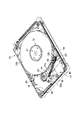
図1および図2に示すように、HDDは、上面の開口した矩形箱状のケース10と、複数のねじによりケースにねじ止めされてケースの上端開口を閉塞する図示しないトップカバーと、を有している。
As shown in FIG. 1 and FIG. 2, the HDD has a rectangular box-
ケース10内には、記録媒体としての2枚の磁気ディスク12a、12b、これらの磁気ディスクを支持および回転させるスピンドルモータ13、磁気ディスクに対して情報の記録、再生を行なう複数の磁気ヘッド、これらの磁気ヘッドを磁気ディスク12a、12bに対して移動自在に支持したヘッドアクチュエータ14、ヘッドアクチュエータを回動および位置決めするボイスコイルモータ(以下VCMと称する)16、磁気ヘッドが磁気ディスクの最外周に移動した際、磁気ヘッドを磁気ディスクから離間した位置に保持するランプロード機構18、ヘッドクチュエータを退避位置に保持するイナーシャラッチ機構20、およびプリアンプ等の回路部品が実装されたフレキシブルプリント回路基板ユニット(以下、FPCユニットと称する)17が収納されている。
In the
ケース10の底壁外面には、FPCユニット17を介してスピンドルモータ13、VCM16、および磁気ヘッドの動作を制御する図示しないプリント回路基板がねじ止めされ、ケースの底壁と対向して位置している。
A printed circuit board (not shown) that controls the operation of the
各磁気ディスク12a、12bは、例えば、直径65mm(2.5インチ)に形成され、上面および下面に磁気記録層を有している。2枚の磁気ディスク12a、12bは、スピンドルモータ13の図示しないハブに互いに同軸的に嵌合されているとともにクランプばね21によりクランプされ、ハブの軸方向に沿って所定の間隔をおいて積層されている。そして、磁気ディスク12a、12bは、駆動部としてのスピンドルモータ13により所定の速度で回転駆動される。
Each of the
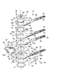
図1ないし図3に示すように、ヘッドアクチュエータ14は、ケース10の底壁上に固定された軸受組立体24を備えている。軸受部として機能する軸受組立体24は、ケース10の底壁に立設された枢軸23と、枢軸に一対の軸受を介して回転自在に支持された円筒形状のハブ26と、を有している。ハブ26の上端には環状のフランジ29が形成され、下端部外周にはねじ部26bが形成されている。
As shown in FIGS. 1 to 3, the
ヘッドアクチュエータ14は、ハブ26に取り付けられた4本のアーム27a、27b、27c、27d、それぞれのアームから延出した4本のサスペンション32、サスペンションの延出端に支持された磁気ヘッド33、および3つのスペーサリング28a、28b、28cを備えている。
The
アーム27aないし27dの各々は、例えば、SUS304等のステンレス系の材料により、板厚250μm程度の薄い平板状に形成され、その一端、つまり、基端には円形の透孔31が形成されている。また、各アーム27aないし27dは、その基端から突出した突部を有し、この突部には位置決め孔35が形成されている。
Each of the
各サスペンション32は、板厚60〜70μmの細長い板ばねにより構成され、その基端がスポット溶接あるいは接着によりアーム27aないし27dの先端に固定され、アームから延出している。なお、サスペンションおよびアームは、同一材料で一体に形成してもよい。
Each
各磁気ヘッド33は、図示しないほぼ矩形状のスライダとこのスライダに形成された記録再生用のMR(磁気抵抗)ヘッドとを有し、サスペンション32の先端部に形成されたジンバル部に固定されている。また、各磁気ヘッド33は、図示しない4つの電極を有している。
Each
一方、図2に示すように、ヘッドアクチュエータ14の各磁気ヘッド33は、それぞれ中継フレキシブルプリント回路基板(以下、中継FPCと称する)62を介して後述するメインFPC42に電気的に接続されている。中継FPC62は、ヘッドアクチュエータ14の各アームおよびサスペンション32の表面に貼り付け固定され、サスペンションの先端からアームの基端に亘って延びている。中継FPC62は、全体として細長い帯状に形成され、その先端は磁気ヘッド33に電気的に接続されているとともに、その基端部はアームの基端から外側に延出し、複数の接続パッドを有した接続部64を構成している。
On the other hand, as shown in FIG. 2, each
図2および図3に示すように、4本のアーム27a、27b、27c、27dは、透孔31にハブ26を挿通することにより、ハブ26の軸方向に沿ってフランジ29上に積層された状態でハブの外周に嵌合されている。スペーサリング28aは、アーム27a、27b間、スペーサリング28bは、アーム27c、27d間、スペーサリング28cは、後述するナット41とアーム27dとの間にそれぞれ挟まれた状態でハブ26の外周に嵌合されている。スペーサリング28aないし28cの各々は外側に突部を有し、この突部に固定用ねじを取り付けるためのねじ取り付け孔39が形成されている。
As shown in FIGS. 2 and 3, the four
ハブ26の外周に嵌合された4本のアーム27aないし27d、およびスペーサリング28a、28b、28cは、ハブ26のねじ部26bに螺合されたナット41とフランジ29との間に挟持され、ハブ26の外周上に固定保持されている。また、アーム27aないし27dに設けられた位置決め孔35、およびスペーサリング28aないし28cに設けられたねじ取り付け孔39には、上方から位置決め用のねじ41が挿通され、最下端のスペーサリング28cのねじ取り付け孔にねじ込まれている。これにより、アーム27aないし27d、およびスペーサリング28aないし28cは、ハブ26の円周方向に対して、互いに所定位置に位置決めされている。そして、4本のアーム27aないし27dはハブ26から同一の方向へ延出し、これらのアームおよびサスペンション32は、ハブ26と一体的に回動可能となっている。
The four
アーム27aおよび27bは所定の間隔を置いて互いに平行に位置し、これらのアームに取り付けられたサスペンション32および磁気ヘッド33は互いに向かい合って位置している。また、アーム27cおよび27dは所定の間隔を置いて互いに平行に位置し、これらのアームに取り付けられたサスペンション32および磁気ヘッド33は互いに向かい合って位置している。
The
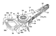
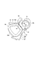
図2ないし図5に示すように、スペーサリング28bは、アーム27aないし27dと反対方向へ延出した一対の支持アーム34を有し、アルミニウム、ステンレス等の金属により一体に形成されている。一対の支持アーム34は、枢軸23に対してほぼ放射方向に延出しているとともに互いに離間して位置し、スペーサリング28bとともにほぼU字形状の支持フレーム37を構成している。
As shown in FIGS. 2 to 5, the
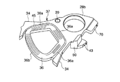
支持フレーム37には、VCM16の一部を構成するボイスコイル36が固定されている。ボイスコイル36は、軸受組立体24の枢軸23とほぼ平行に延びた巻回軸を有し、ほぼ矩形枠状に巻回されている。ボイスコイル36ボイスコイルの外周部は、支持フレーム37に隣接対向した3辺の対向外周部36aと、枢軸23に対して最外周に位置しているとともに外部に露出した1つの露出外周部36bとを有している。
A
そして、ボイスコイル36は、対向外周部36aと支持フレーム37との隙間にインサート成形によりモールドされた樹脂45により支持フレームに固定されている。但し、ボイスコイル36の露出外周部36bは、樹脂によって覆われることなく外部に露出している。ボイスコイル36から延出したリード線46は、スペーサリング28bの表面上に引き回され、モールド成形された樹脂48より覆われた状態でスペーサリングに固定されている。リード線46先端の接続端は、スペーサリング28bの側縁部にモールド成形されたコネクタ50内に埋め込まれている。リード線46の接続端は、コネクタ50内に埋め込まれた接続端子43に接続されている。
The
スペーサリング28bは、アーム27c、27dの一側縁とほぼ面一となる位置まで突出した突出部70を一体に備え、この突出部には、後述するメインFPCの接続端部42aをねじ止めするためのねじ孔72が形成されている。
The
図1からよくわかるように、上記のように構成されたヘッドアクチュエータ14をケース10に組み込んだ状態において、磁気ディスク12aはアーム27a、27b間に位置し、また、磁気ディスク12bはアーム27c、27d間に位置する。
As can be seen from FIG. 1, in the state where the
HDDの動作時、アーム27a、27bに取り付けられた磁気ヘッド33は、磁気ディスク12aの上面および下面にそれぞれ対向し、磁気ディスク12aを両面側から挟持する。同様に、アーム27c、27dに取り付けられた磁気ヘッド33は、磁気ディスク12bの上面および下面にそれぞれ対向し、磁気ディスク12bを両面側から挟持する。
During the operation of the HDD, the
ヘッドアクチュエータ14をケース10に組み込んだ状態において、支持フレーム37に固定されたボイスコイル36は、ケース10上に固定された一対のヨーク38間に位置する。ボイスコイル36は、これらのヨーク38および一方のヨークに固定された図示しない磁石とともにVCM16を構成している。ボイスコイル36に通電することにより、ヘッドアクチュエータ14が回動し、磁気ヘッド33は磁気ディスク12a、12bの所望のトラック上に移動および位置決めされる。
In a state where the
図1に示すように、FPCユニット17は、フレキシブルプリント回路基板をほぼ矩形状に折り曲げて形成されたベース部40と、ベース部から延出した細長い帯状のメインフレキシブルプリント回路基板(以下、メインFPCと称する)42と、を有し、共通のフレキシブルプリント回路基板により一体的に形成されている。メインFPC42の延出端部は接続端部42aを構成している。図2に示すように、接続端部42aの一方の表面には多数の接続パッド44が形成され、各接続パッドはメインFPC42の図示しない導体配線を通してベース部40側に電気的に接続されている。接続端部42aの他方の表面には、ほぼ矩形板状の補強板51が固定されている。接続端部42aおよび補強板51には、透孔58が貫通形成されている。そして、接続端部42aは、固定ねじ74を、透孔58を通してスペーサリング28bのねじ孔72にねじ込むことにより、ヘッドアクチュエータ14の基端部にねじ止めされている。
As shown in FIG. 1, the
図2および図3に示すように、アーム27aないし27bから延出している中継FPC62の接続部64は、メインFPC42の接続端部42a上に位置決め配置されている。各接続部64の接続パッドは接続端部42a側の対応する接続パッド44にハンダ付けされている。これにより、メインFPC42と4つの中継FPC62とが電気的かつ機械的に接続されている。言い換えると、ヘッドアクチュエータ14とFPCユニット17とが電気的かつ機械的に接続され、ヘッドアクチュエータユニットが形成されている。
As shown in FIGS. 2 and 3, the
上記のように構成されたHDDによれば、ボイスコイル36は、支持フレーム37に対して、モールド成形された樹脂45により固定されている。また、ボイスコイル36のリード線46は、モールド成形された樹脂48により覆われ、所定の形状に成形された状態でスペーサリング28bに固定されている。従って、インサート成形により、ボイスコイル36の固定とリード線46のフォーミングとを同時に行うことができ、製造工程を低減しヘッドアクチュエータを効率良く製造することができる。
According to the HDD configured as described above, the
同時に、ボイスコイル36の支持部として、金属等の剛性の高い材料で形成された支持フレーム37を用い、インサート成形された樹脂によって固定することにより、ボイスコイルの保持力が強固となり、共振周波数を上げることができる。この際、ボイスコイル36の最外周に位置した露出外周部36bは樹脂で覆われることなく露出していることから、ヘッドアクチュエータの寸法を共通とした場合、コイル有効線長を最大限に延ばすことができる。
At the same time, by using a
コイル端子の処理も必要な部分にのみ配置させることができ、不用意に本来あるべき箇所でないところでワイヤーを切断してしまったり、リード線の浮きが発生することを防止することが出来る。 The coil terminal can be disposed only in a necessary portion, and it is possible to prevent the wire from being inadvertently cut at a place where it should not be, or the lead wire from being lifted.
具体的に言うと、本発明の構造によれば、リード線は、その導体部は樹脂内に納まり、露出する部分は、FPCに接合される部分そのものであるために、従来のリード線剥き出しに比べ、リード線の配置を手作業で整えるフォーミング等作業が不要になり、この作業中に発生するリード線の断線や、取り付け時のリード線の浮きの発生を避けられる。 More specifically, according to the structure of the present invention, the lead wire has its conductor portion housed in the resin, and the exposed portion is the portion that is joined to the FPC itself. In comparison, it is not necessary to perform a work such as forming to manually arrange the lead wires, and it is possible to avoid the disconnection of the lead wires that occur during this operation and the occurrence of floating of the lead wires during the installation.
なお、本発明は上記実施形態そのままに限定されるものではなく、実施段階ではその要旨を逸脱しない範囲で構成要素を変形して具体化できる。また、上記実施形態に開示されている複数の構成要素の適宜な組み合わせにより、種々の発明を形成できる。例えば、実施形態に示される全構成要素から幾つかの構成要素を削除してもよい。さらに、異なる実施形態にわたる構成要素を適宜組み合わせてもよい。 Note that the present invention is not limited to the above-described embodiment as it is, and can be embodied by modifying the constituent elements without departing from the scope of the invention in the implementation stage. In addition, various inventions can be formed by appropriately combining a plurality of components disclosed in the embodiment. For example, some components may be deleted from all the components shown in the embodiment. Furthermore, constituent elements over different embodiments may be appropriately combined.
例えば、HDDにおいて、磁気ディスクの枚数は1枚に限らず、必要に応じて増加可能である。この発明は、磁気ディスク装置に限らず、光ディスク装置等の他のディスク装置にも適用することができる。 For example, in the HDD, the number of magnetic disks is not limited to one, and can be increased as necessary. The present invention can be applied not only to the magnetic disk device but also to other disk devices such as an optical disk device.
10…ベース、 11…底壁、 12a、12b…磁気ディスク、
13…スピンドルモータ、 16…VCM、 34…支持アーム、
36…ボイスコイル、 36a…対向外周部、 36b…露出外周部、
45、48…樹脂、 46…リード線、 50…コネクタ
10 ... Base, 11 ... Bottom wall, 12a, 12b ... Magnetic disk,
13 ... Spindle motor, 16 ... VCM, 34 ... Support arm,
36 ... Voice coil, 36a ... Opposing outer periphery, 36b ... Exposed outer periphery,
45, 48 ... Resin, 46 ... Lead wire, 50 ... Connector
Claims (3)
前記ヘッドアクチュエータは、前記軸受部から延出しているとともに金属で形成された支持フレームを有し、
前記ボイスコイルモータは、前記ヘッドアクチュエータの回転軸とほぼ平行に延びた巻回中心軸を有し前記支持フレーム間に配置されたボイスコイルと、前記ボイスコイルから延出しているとともに接続端を有したリード線とを備え、
前記ボイスコイルの外周部は、前記支持フレームに対向した対向外周部と、前記軸受部に対して最外周に位置しているとともに外部に露出した露出外周部とを有し、このボイスコイルは、前記対向外周部と前記支持フレームと間にモールド成形された樹脂により前記支持フレームに固定されて、前記リード線は、モールド成形された樹脂により覆われ前記ヘッドアクチュエータの所定位置に固定されているディスク装置。 A disk-shaped recording medium, a motor that supports and rotates the recording medium, a head that performs information processing on the recording medium, and a bearing that is pivotable around a bearing portion; A head actuator supported so as to be movable with respect to a recording medium, and a voice coil motor that rotates the head actuator around the bearing portion,
The head actuator has a support frame extending from the bearing portion and formed of metal,
The voice coil motor has a winding center axis extending substantially parallel to the rotation axis of the head actuator, a voice coil disposed between the support frames, and extending from the voice coil and having a connection end. Lead wire,
The outer peripheral portion of the voice coil has an opposing outer peripheral portion facing the support frame, and an exposed outer peripheral portion that is located on the outermost periphery with respect to the bearing portion and exposed to the outside. A disk that is fixed to the support frame by a resin molded between the opposed outer peripheral portion and the support frame, and the lead wire is covered with the molded resin and fixed to a predetermined position of the head actuator. apparatus.
Priority Applications (4)
| Application Number | Priority Date | Filing Date | Title |
|---|---|---|---|
| JP2004107649A JP2005293719A (en) | 2004-03-31 | 2004-03-31 | Disk unit |
| SG200502257A SG115834A1 (en) | 2004-03-31 | 2005-03-10 | Disk device |
| US11/087,700 US20050219761A1 (en) | 2004-03-31 | 2005-03-24 | Disk device |
| CN200510059167.6A CN1677548A (en) | 2004-03-31 | 2005-03-24 | Disk device |
Applications Claiming Priority (1)
| Application Number | Priority Date | Filing Date | Title |
|---|---|---|---|
| JP2004107649A JP2005293719A (en) | 2004-03-31 | 2004-03-31 | Disk unit |
Publications (1)
| Publication Number | Publication Date |
|---|---|
| JP2005293719A true JP2005293719A (en) | 2005-10-20 |
Family
ID=35049996
Family Applications (1)
| Application Number | Title | Priority Date | Filing Date |
|---|---|---|---|
| JP2004107649A Withdrawn JP2005293719A (en) | 2004-03-31 | 2004-03-31 | Disk unit |
Country Status (4)
| Country | Link |
|---|---|
| US (1) | US20050219761A1 (en) |
| JP (1) | JP2005293719A (en) |
| CN (1) | CN1677548A (en) |
| SG (1) | SG115834A1 (en) |
Families Citing this family (2)
| Publication number | Priority date | Publication date | Assignee | Title |
|---|---|---|---|---|
| JP4526400B2 (en) * | 2005-01-26 | 2010-08-18 | 京セラミタ株式会社 | Shaft joint and image forming apparatus having the same |
| JP2016110675A (en) * | 2014-12-09 | 2016-06-20 | 日本電産株式会社 | Spindle motor, disk drive device, and manufacturing method of base unit of spindle motor |
Family Cites Families (3)
| Publication number | Priority date | Publication date | Assignee | Title |
|---|---|---|---|---|
| US5734528A (en) * | 1992-08-04 | 1998-03-31 | Seagate Technology, Inc. | Disc drive actuator incorporating injection molding, flying leads, and locking flanges |
| US5621591A (en) * | 1996-04-05 | 1997-04-15 | Seagate Technology, Inc. | Dual coil voice coil motor |
| JPH1196526A (en) * | 1997-09-24 | 1999-04-09 | Internatl Business Mach Corp <Ibm> | Actuator arm assembly and disk memory device |
-
2004
- 2004-03-31 JP JP2004107649A patent/JP2005293719A/en not_active Withdrawn
-
2005
- 2005-03-10 SG SG200502257A patent/SG115834A1/en unknown
- 2005-03-24 US US11/087,700 patent/US20050219761A1/en not_active Abandoned
- 2005-03-24 CN CN200510059167.6A patent/CN1677548A/en active Pending
Also Published As
| Publication number | Publication date |
|---|---|
| US20050219761A1 (en) | 2005-10-06 |
| CN1677548A (en) | 2005-10-05 |
| SG115834A1 (en) | 2005-10-28 |
Similar Documents
| Publication | Publication Date | Title |
|---|---|---|
| CN111724819B (en) | Disk device | |
| US10475475B2 (en) | Disk apparatus and dual actuator assembly having a wiring board with a bent connection portion | |
| US20080307636A1 (en) | Method of manufacturing head actuator assembly and method of manufacturing disk device | |
| US11276425B2 (en) | Disk device and manufacturing method thereof | |
| JP2022125632A (en) | disk device | |
| US20140362467A1 (en) | Head suspension assembly and disk device with the assembly | |
| CN115602203A (en) | disk device | |
| JP3597822B2 (en) | Head support device and recording / reproducing device provided with the same | |
| JP2013125578A (en) | Base plate for hard disk drive and hard disk drive including the same | |
| US8254064B2 (en) | Head gimbal assembly and disk drive with the same | |
| CN111653293B (en) | Disk device | |
| US20050068682A1 (en) | Head actuator assembly and disk drive provided with the same | |
| CN1327439C (en) | Magnetic head actuator mechanism and manufacturing method thereof | |
| JP2005293719A (en) | Disk unit | |
| JP4869423B2 (en) | Head gimbal assembly and disk device provided with the same | |
| JP2008165880A (en) | Head actuator assembly and disk device having the same | |
| JP4309454B2 (en) | Head stack assembly and disk drive device having the same | |
| JP2012014794A (en) | Head gimbal assembly and disk device provided with the same | |
| JP2012014793A (en) | Head suspension assembly and disk device with the same | |
| JP2008135172A (en) | Manufacturing method of head actuator assembly and disk device | |
| JP4435247B2 (en) | Head stack assembly and disk drive device having the same | |
| JP3715434B2 (en) | Magnetic disk drive and assembly method thereof | |
| JP2003217249A (en) | Disk mounting mechanism and disk device having the same | |
| JP2006048764A (en) | Disk unit | |
| US20070064341A1 (en) | Hard disk drive |
Legal Events
| Date | Code | Title | Description |
|---|---|---|---|
| A621 | Written request for application examination |
Free format text: JAPANESE INTERMEDIATE CODE: A621 Effective date: 20060227 |
|
| A761 | Written withdrawal of application |
Free format text: JAPANESE INTERMEDIATE CODE: A761 Effective date: 20061002 |