JP2005293548A - Adapter for smoke sensor - Google Patents

Adapter for smoke sensor Download PDF

Info

Publication number
JP2005293548A
JP2005293548A JP2004306873A JP2004306873A JP2005293548A JP 2005293548 A JP2005293548 A JP 2005293548A JP 2004306873 A JP2004306873 A JP 2004306873A JP 2004306873 A JP2004306873 A JP 2004306873A JP 2005293548 A JP2005293548 A JP 2005293548A
Authority
JP
Japan
Prior art keywords
smoke
flow path
adapter
drain hole
smoke detector
Prior art date
Legal status (The legal status is an assumption and is not a legal conclusion. Google has not performed a legal analysis and makes no representation as to the accuracy of the status listed.)
Granted
Application number
JP2004306873A
Other languages
Japanese (ja)
Other versions
JP4258734B2 (en
Inventor
Daizo Matsuda
大造 松田
Current Assignee (The listed assignees may be inaccurate. Google has not performed a legal analysis and makes no representation or warranty as to the accuracy of the list.)
Nohmi Bosai Ltd
Original Assignee
Nohmi Bosai Ltd
Priority date (The priority date is an assumption and is not a legal conclusion. Google has not performed a legal analysis and makes no representation as to the accuracy of the date listed.)
Filing date
Publication date
Application filed by Nohmi Bosai Ltd filed Critical Nohmi Bosai Ltd
Priority to JP2004306873A priority Critical patent/JP4258734B2/en
Publication of JP2005293548A publication Critical patent/JP2005293548A/en
Application granted granted Critical
Publication of JP4258734B2 publication Critical patent/JP4258734B2/en
Expired - Fee Related legal-status Critical Current
Anticipated expiration legal-status Critical

Links

Images

Landscapes

  • Fire-Detection Mechanisms (AREA)

Abstract

<P>PROBLEM TO BE SOLVED: To easily prevent the existing smoke sensor from giving erroneous report by steam. <P>SOLUTION: In this adapter 1 of the smoke sensor to be installed in periphery of a smoke sensing part 31 of the smoke sensor, an outlet 7 oppositely provided in a smoke inlet 35 of the smoke sensor and an inlet 9 provided via the outlet 7 via a conduit 10 are formed in the adapter. A drain hole 15 opening downward is provided in the adapter and the drain hole and the conduit 10 are connected. The conduit 10 is formed by a horizontal conduit 11 extended from the inlet 9 to the inside, a down conduit 12 extended downward from the horizontal conduit to the drain hole 15 and an inclined conduit 13 which rises from the middle of the down conduit to the output 7 and in the flat shape with low height. <P>COPYRIGHT: (C)2006,JPO&NCIPI

Description

本発明は、煙感知器のアダプタに関するもので、例えば、既存の煙感知器に取り付けられ、湯気による誤報を防止するアダプタに関するものである。   The present invention relates to an adapter for a smoke detector, for example, an adapter that is attached to an existing smoke detector and prevents false alarms due to steam.

従来より火災を検知する火災感知器の一つとして火災時の煙を検出する煙感知器がある。煙感知器は、タバコの煙や湯沸かし器等から発生する湯気によって誤報を発する場合があった。このため、防虫網の開口率を変化させたり(例えば、特許文献1参照)、感知器本体の形状を工夫して(例えば、特許文献2参照)、誤報を防止する対策を施したものが提案されている。
特開2003−85664号公報 特開平9−153187号公報
Conventionally, there is a smoke detector that detects smoke during a fire as one of the fire detectors that detect a fire. Smoke detectors sometimes gave false alarms due to cigarette smoke or steam generated from a water heater. For this reason, changing the aperture ratio of the insect screen (for example, refer to Patent Document 1), devising the shape of the sensor body (for example, refer to Patent Document 2), and taking measures to prevent false alarms are proposed. Has been.
JP 2003-85664 A JP-A-9-153187

ところで、室内において、風呂場付近に設置された煙感知器は、寝室などに設置された煙感知器に比べ、湯気にさらされることが多く、湯気により誤報を起こす可能性が高い。このような湯気による誤報対策を施した煙感知器がいくつか提案されているが、既に設置された煙感知器に対して、交換することなく容易に湯気による誤報を防止することはできず、例えば、風呂場付近の煙感知器だけに湯気の誤報防止手段を設けるということができなかった。   By the way, smoke detectors installed in the vicinity of a bathroom in a room are often exposed to steam compared to smoke detectors installed in a bedroom or the like, and there is a high possibility of causing false alarms due to steam. Several smoke detectors have been proposed that take measures against false alarms due to steam, but it is not possible to easily prevent false alarms due to steam without having to replace smoke detectors already installed. For example, it was not possible to provide a means for preventing misreporting of steam only in a smoke detector near a bathroom.

そこで、本発明は、例えば既設の煙感知器に対しても、容易に湯気による誤報を防止できるようにした煙感知器のアダプタを提供すること目的としたものである。   Therefore, an object of the present invention is to provide an adapter for a smoke detector that can easily prevent erroneous reporting due to steam, for example, even for an existing smoke detector.

本発明は以上の課題を解決するためになされたもので、煙感知器の煙感知部の外周に取り付けられる煙感知器のアダプタであって、煙感知器の煙流入口に対向して設けられる流出口と、その流出口と流路を介して設けられる流入口とをアダプタに設けたことを特徴とするものである。また、アダプタに下方に開口した水抜き穴を設け、該水抜き穴と前記流路を連通したことを特徴とするものである。そして流路を、流入口から内側に延びた水平流路と、該水平流路から水抜き穴へ下方へ延びた下り流路と、該下り流路の途中から前記流出口へ上がる傾斜流路とから形成して、高さの低い偏平な形状にした。   The present invention has been made to solve the above problems, and is an adapter for a smoke detector that is attached to the outer periphery of the smoke detector of the smoke detector, and is provided opposite to the smoke inlet of the smoke detector. The adapter is provided with an outlet and an inlet provided through the outlet and the flow path. Further, the adapter is provided with a drain hole that opens downward, and the drain hole communicates with the flow path. The flow path includes a horizontal flow path extending inward from the inlet, a downward flow path extending downward from the horizontal flow path to the drain hole, and an inclined flow path rising from the middle of the downward flow path to the outlet. And formed into a flat shape with a low height.

本発明は、アダプタの内部に流路を形成し、そのアダプタを煙感知器の煙感知部の外周に取り付けたので、火災による煙は流路内をそのまま通過して煙感知部へと流入するが、湯気は流路の途中で水滴になり、湯気が煙感知部へ流入することはない。このため湯気による誤報を防止することができる。また流路内で湯気が水になると、その水滴は水抜き穴から排出されるので、流路に水滴が溜まることはない。   In the present invention, since the flow path is formed inside the adapter and the adapter is attached to the outer periphery of the smoke detector of the smoke detector, the smoke from the fire passes through the flow path as it is and flows into the smoke detector. However, the steam becomes water droplets in the middle of the flow path, and the steam does not flow into the smoke sensing unit. For this reason, misreporting by steam can be prevented. Further, when the steam becomes water in the flow path, the water droplets are discharged from the drain hole, so that water drops do not accumulate in the flow path.

[実施の形態1]
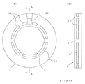
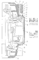
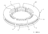
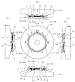
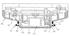
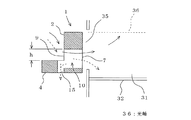
図1(a)は本発明の実施の形態1に係るアダプタの平面図、図1(b)はアダプタの側面図、図2はアダプタを煙感知器に取り付けた状態を示す断面図である。図3(a)は図1のA−A線の断面図で、図3(b)は図3(a)のB−Bの断面図、図4はアダプタを煙感知器取付側から見た平面図、図5はアダプタの斜視図である。なお、アダプタは、図2に示すように天井に取り付けた火災感知器としての煙感知器に取り付ける関係上、以下の説明では、煙感知器側を上側、アダプタの水抜き穴のある側を下側として上下方向を説明する。
[Embodiment 1]
1A is a plan view of an adapter according to Embodiment 1 of the present invention, FIG. 1B is a side view of the adapter, and FIG. 2 is a cross-sectional view showing a state where the adapter is attached to a smoke detector. 3A is a cross-sectional view taken along the line AA in FIG. 1, FIG. 3B is a cross-sectional view taken along the line BB in FIG. 3A, and FIG. 4 is a view of the adapter as viewed from the smoke detector mounting side. FIG. 5 is a perspective view of the adapter. Note that the adapter is attached to the smoke detector as a fire detector attached to the ceiling as shown in FIG. 2, so in the following description, the smoke detector side is on the upper side, and the side with the drain hole of the adapter is on the lower side. The vertical direction will be described as a side.

図において、1はアダプタで、煙感知器の湯気による誤報を防止するための器具である。アダプタ1は図2に示すように、煙感知器30の煙感知部31の外周に取り付けられる。煙感知部31は、一対の発光素子と受光素子とを有する光学室から構成され、光学室(煙感知部31)の外周には、防虫網33を介して煙流入口35が設けられている。37は火災時に点灯する確認灯である。なお、煙感知器30は、公知のもので、特に新規の部分はないので、本発明のアダプタ1の説明に関係する部分だけを説明する。   In the figure, reference numeral 1 denotes an adapter, which is an instrument for preventing false alarms caused by steam on the smoke detector. As shown in FIG. 2, the adapter 1 is attached to the outer periphery of the smoke detector 31 of the smoke detector 30. The smoke detection unit 31 includes an optical chamber having a pair of light emitting elements and light receiving elements, and a smoke inlet 35 is provided on the outer periphery of the optical chamber (smoke detection unit 31) via an insect screen 33. . Reference numeral 37 denotes a confirmation light that is turned on in the event of a fire. Note that the smoke detector 30 is a known one, and there is no particular novel part, so only the part related to the description of the adapter 1 of the present invention will be described.

アダプタ1は樹脂などで成型され、中央に嵌合穴3を有しており、ほぼドーナツ状に形成されている。中央の嵌合穴3は、その内径が煙感知部31の外径とほぼ同じ大きさに形成され、図2に示すように、嵌合穴3を煙感知器30のカバー32の下から挿入して、アダプタ1が保持されるようになっている。より詳しく説明すると、アダプタ1の嵌合穴3の内周縁部5の上部5cは、僅かに突出している。そして、煙感知器30にアダプタ1を取り付ける際、煙感知器30の煙流入口35の周りに設けられた、カバー32の開口内に、内周縁部5及びその上部5cが食い込んで、アダプタ1は外れにくくなっている。   The adapter 1 is molded of resin or the like, has a fitting hole 3 in the center, and is formed in a substantially donut shape. The inner fitting hole 3 has an inner diameter that is substantially the same as the outer diameter of the smoke detector 31, and the fitting hole 3 is inserted from below the cover 32 of the smoke detector 30 as shown in FIG. 2. Thus, the adapter 1 is held. If it demonstrates in detail, the upper part 5c of the inner peripheral part 5 of the fitting hole 3 of the adapter 1 will protrude slightly. When the adapter 1 is attached to the smoke detector 30, the inner peripheral edge portion 5 and the upper portion 5c thereof bite into the opening of the cover 32 provided around the smoke inlet 35 of the smoke detector 30, and the adapter 1 Is hard to come off.

アダプタ1には、流出口7、流入口9、流路10及び水抜き穴15が形成されている。流出口7は、内周縁部5の煙感知器30の煙流入口35に対向した位置に設けられており、また流入口9は、流出口7と流路10を介して連通し、アダプタ1の外周面6に開口している。そして流出口7は、流入口9よりも低い位置、つまり高さ方向において下側方向に設けられている。水抜き穴15は、アダプタ1の底面に下方に開口するように設けられ、流路10と連通している。   The adapter 1 has an outlet 7, an inlet 9, a flow path 10, and a drain hole 15. The outlet 7 is provided at a position facing the smoke inlet 35 of the smoke detector 30 on the inner peripheral edge 5, and the inlet 9 communicates with the outlet 7 via the flow path 10, and the adapter 1. The outer peripheral surface 6 is opened. The outflow port 7 is provided at a position lower than the inflow port 9, that is, in a lower direction in the height direction. The drain hole 15 is provided on the bottom surface of the adapter 1 so as to open downward, and communicates with the flow path 10.

図3(b)を用いて、流入口9などの形状について更に説明する。流入口9はアダプタ1の外周面6において放射状に設けられ、図では7つの横長の(スリット状の)流入口9が形成されている(図1(b)参照)。流入口9はその先端はテーパ状に形成されており、開口を大きくして煙が流入しやすくなっている。流入口9に連通する流路10はほぼ扇形状に形成され、内側にいくほど幅が狭くなり、嵌合穴3のある内周面に開口した流出口7と連通している。このため流出口7も横長のスリット形状になっている。   The shape of the inlet 9 will be further described with reference to FIG. The inflow ports 9 are provided radially on the outer peripheral surface 6 of the adapter 1, and in the figure, seven horizontally long (slit-shaped) inflow ports 9 are formed (see FIG. 1B). The tip of the inflow port 9 is formed in a tapered shape, and the opening is enlarged so that smoke can easily flow in. The flow path 10 communicating with the inflow port 9 is formed in a substantially fan shape, the width becomes narrower toward the inner side, and communicates with the outflow port 7 opened on the inner peripheral surface with the fitting hole 3. For this reason, the outflow port 7 also has a horizontally long slit shape.

再び図2に戻って、流路10について説明する。流路10は、水平流路11,下り流路12及び傾斜流路13とから形成されている。水平流路11は、流入口9から水平に内側に向かって延びた流路である。下り流路12は、その水平流路11から水抜き穴15に向かって下方へ延びた流路であり、この下り流路12と水平流路11でほぼ断面L字状に形成される。傾斜流路13は、下り流路12の途中から流出口7へ向かって上方に傾斜する流路である。なお、水平流路11は下方又は上方に傾斜した流路であってもよく、またL字状の流路を複数組み合わせて、流路を形成するようにしてもよい。   Returning to FIG. 2 again, the flow path 10 will be described. The flow path 10 is formed of a horizontal flow path 11, a downward flow path 12, and an inclined flow path 13. The horizontal flow path 11 is a flow path that extends horizontally inward from the inflow port 9. The down flow path 12 is a flow path extending downward from the horizontal flow path 11 toward the drain hole 15, and the down flow path 12 and the horizontal flow path 11 are formed in a substantially L-shaped cross section. The inclined channel 13 is a channel inclined upward from the middle of the downstream channel 12 toward the outlet 7. The horizontal channel 11 may be a channel inclined downward or upward, or a plurality of L-shaped channels may be combined to form a channel.

図4において、20は投光窓で、煙感知器30の確認灯37と対向した位置に形成されている。アダプタ1の底面側において、この投光窓20が形成される部分は切り欠かれており、火災時に確認灯37が点灯したことを外部から視認できる形状になっている(図1(a)、図2及び図5参照)。なお、図4において、21は放射状に形成された嵌合溝でアダプタ1の上面側に設けられる。この嵌合溝21は、煙感知器30のカバー32に設けた図示しないフィン(カバー32から立ち上がった複数本の壁)に嵌合する細長い溝である。このフィンは煙感知器30によって必要に応じて設けられるので、嵌合溝21は省略してもよい。   In FIG. 4, reference numeral 20 denotes a light projection window, which is formed at a position facing the confirmation lamp 37 of the smoke detector 30. On the bottom side of the adapter 1, the portion where the light projection window 20 is formed is cut out, and is shaped so that the confirmation lamp 37 can be seen from the outside during a fire (FIG. 1A). 2 and 5). In FIG. 4, reference numeral 21 denotes a fitting groove formed radially and provided on the upper surface side of the adapter 1. The fitting groove 21 is an elongated groove that fits into fins (not shown) provided on the cover 32 of the smoke detector 30 (a plurality of walls rising from the cover 32). Since the fin is provided as necessary by the smoke sensor 30, the fitting groove 21 may be omitted.

次に、本実施形態のアダプタ1の作用につき、まず煙感知器30の近辺で火災が発生し、煙が生じた場合について説明する。火災時の煙は図示しない天井面に到達すると、天井下面に沿って水平方向に流れ、その一部は流入口9から流入し、流路10の水平流路11を通って下り流路12へと流れる。煙は上昇するように流れるから、下り流路12を通る際、水抜き穴15からほとんど流出せずに、傾斜流路13側へ流れる。そして傾斜流路13から流出口7及び煙流入口35を通って煙感知部31に到達し、所定濃度の煙が検知されると、確認灯37が点灯する。なお、傾斜流路13の幅(径)を下り流路12の幅よりも広くすれば、又は水抜き穴15の径を小さくすれば、それだけ煙は流出口7側へ流れやすくなり、水抜き穴15から流出する煙量を減らすことが可能になる。   Next, the operation of the adapter 1 according to the present embodiment will be described in the case where a fire has occurred near the smoke detector 30 and smoke has been generated. When the fire smoke reaches a ceiling surface (not shown), the smoke flows in a horizontal direction along the lower surface of the ceiling. A part of the smoke flows in from the inlet 9 and passes through the horizontal flow path 11 of the flow path 10 to the down flow path 12. And flow. Since smoke flows so as to rise, when passing through the downward flow path 12, it hardly flows out of the drain hole 15 and flows toward the inclined flow path 13. When the smoke sensor 31 is reached from the inclined channel 13 through the outlet 7 and the smoke inlet 35 and smoke of a predetermined concentration is detected, the confirmation lamp 37 is turned on. Note that if the width (diameter) of the inclined flow path 13 is made wider than the width of the down flow path 12 or the diameter of the drain hole 15 is made smaller, the smoke easily flows to the outlet 7 side. It is possible to reduce the amount of smoke flowing out from the hole 15.

続いて、煙感知器30の近辺において、風呂場や湯沸かし器等から湯気が発生する場合について説明する。ここで湯気と煙との違いは、湯気の方が煙より粒子径が大きく、また粘性が高く、温度差がある点であり、この特性の違いを利用して湯気の煙感知部31への浸入を防止する。湯気が天井面に立ち上がると、煙と同様にアダプタ1の流入口9から流入する。流入口9に入った湯気は、流路10を通る際、流路10の壁面に付着して、その一部は水滴へと変化する。このように湯気は、低い温度のアダプタ1を通ることで、飽和量が下がるため水滴として現れる。   Next, a case where steam is generated from a bathroom, a water heater, or the like in the vicinity of the smoke detector 30 will be described. Here, the difference between steam and smoke is that steam has a larger particle diameter than smoke and has a higher viscosity and a temperature difference. Using this difference in characteristics, steam is sent to the smoke detector 31. Prevent intrusion. When steam rises on the ceiling surface, it flows from the inlet 9 of the adapter 1 like smoke. When the steam that has entered the inflow port 9 passes through the flow path 10, it adheres to the wall surface of the flow path 10, and a part thereof changes into water droplets. In this way, the steam appears as water droplets because the saturation amount decreases by passing through the adapter 1 having a low temperature.

ここで流路10について詳しく説明する。仮に流入口9から流出口7までを水平流路11だけで連通すると、流入口9から流入した湯気は、流路10の壁面に付着して流路10内で水滴となるが、それでも湯気の一部は、流出口7から直接煙流入口35へと流入してしまう。   Here, the flow path 10 will be described in detail. If the inlet 9 to the outlet 7 communicate with each other only through the horizontal flow path 11, the steam flowing in from the inlet 9 adheres to the wall surface of the flow path 10 and becomes water droplets in the flow path 10. A part flows into the smoke inlet 35 directly from the outlet 7.

そこで流入口9と流出口7との間に段差を設けて、つまり、本実施形態のように水平流路11を下り流路12という壁にぶつけて、更に傾斜流路13を介して流出口7へと導くことにより、流入口9から流出口7までの距離を長くできる。これにより上述した湯気の壁面への付着による水滴化を促進することができる。特に、水平流路11は、高さの低い偏平な形状を有しているため、湯気が水平流路11の壁面へ付着しやすくなっている。   Therefore, a step is provided between the inflow port 9 and the outflow port 7, that is, the horizontal flow path 11 hits the wall called the down flow path 12 as in the present embodiment, and the outflow port further passes through the inclined flow path 13. By guiding to 7, the distance from the inlet 9 to the outlet 7 can be increased. Thereby, formation of water droplets due to adhesion of the steam to the wall surface can be promoted. In particular, since the horizontal flow path 11 has a flat shape with a low height, steam is likely to adhere to the wall surface of the horizontal flow path 11.

また、流路10内で湯気が水滴になると、その水滴は下り流路12を通って水抜き穴15から排出されるので、流路10内に水が溜まることはない。そして下り流路12から流出口7へは上り傾斜の傾斜流路13となっているので、水滴となった水が煙流入口35へと浸入するのを防止できる。   Further, when the steam becomes water droplets in the flow path 10, the water drops are discharged from the drain hole 15 through the down flow path 12, so that water does not accumulate in the flow path 10. Since the inclined channel 13 is inclined upward from the downstream channel 12 to the outlet 7, it is possible to prevent water that has become water droplets from entering the smoke inlet 35.

このように流路10を有するアダプタ1を、煙感知器30の煙感知部31の外周に取り付けることで、火災による煙は流路10内をそのまま通過して、煙感知部31へと流入しやすいが、湯気は流路10の途中で水滴になり、煙感知部31に流入することはない。このため湯気による誤報を防止することができる。   By attaching the adapter 1 having the flow channel 10 to the outer periphery of the smoke detection unit 31 of the smoke detector 30 as described above, smoke from the fire passes through the flow channel 10 as it is and flows into the smoke detection unit 31. Although it is easy, the steam becomes water droplets in the middle of the flow path 10 and does not flow into the smoke detection unit 31. For this reason, misreporting by steam can be prevented.

次に、考えられる他の例について説明する。例えば、水抜き穴15の一部を覆うか又は塞ぐようにしてもよい。水抜き穴15はアダプタ1の底面16に形成されることから、ここから煙や湯気が流入して、傾斜流路13を介して煙流入口35へ流れる場合がある。このため、このような流れを少なくするために、水抜き穴15の一部をテープなどで覆うか、塞ぐようにして、水抜き穴15の開口面積を減らすことが望ましい。勿論、アダプタ1の成形時に、水抜き穴15の開口を小さくするように成形してもよい。こうして、水抜き穴15を通って煙感知部31へ流れ込む湯気を減らすことができる。なお、水抜き穴15の全ての開口面積は、流出口7の全開口面積よりも小さくすることが好ましい。   Next, another possible example will be described. For example, a part of the drain hole 15 may be covered or closed. Since the drain hole 15 is formed in the bottom surface 16 of the adapter 1, smoke or steam may flow from here and flow to the smoke inlet 35 via the inclined flow path 13. For this reason, in order to reduce such a flow, it is desirable to reduce the opening area of the drain hole 15 by covering or closing a part of the drain hole 15 with a tape or the like. Of course, you may shape | mold so that the opening of the drain hole 15 may be made small at the time of shaping | molding of the adapter 1. FIG. In this way, the steam flowing into the smoke detector 31 through the drain hole 15 can be reduced. In addition, it is preferable that the entire opening area of the drain hole 15 is smaller than the entire opening area of the outlet 7.

本実施の形態は、アダプタの内部に形成し、そのアダプタを煙感知器の煙感知部の外周に取り付けたので、火災による煙は流路内をそのまま通過して煙感知部へと流入するが、湯気は流路の途中に水滴のになり、湯気が煙感知部へ流入することはない。このため湯気による誤報を防止することができる。また、流路内で湯気が水滴になると、その水滴は水抜き穴から排出されるので、流路に溜まることはない。さらに、水抜き穴の一部を覆うか又は塞ぐことで、水抜き穴の開口面積を減らすことで、水抜き穴を通って煙感知部へ流れ込む湯気を減らすことができる。   In the present embodiment, the adapter is formed inside the adapter, and the adapter is attached to the outer periphery of the smoke detector of the smoke detector. Therefore, smoke from the fire passes through the flow path as it is and flows into the smoke detector. The steam becomes droplets in the middle of the flow path, and the steam does not flow into the smoke sensing unit. For this reason, misreporting by steam can be prevented. Further, when the steam becomes water droplets in the flow channel, the water droplets are discharged from the drain hole, so that they do not accumulate in the flow channel. Furthermore, by covering or closing a part of the drain hole, the opening area of the drain hole can be reduced, so that steam flowing into the smoke sensing unit through the drain hole can be reduced.

[実施の形態2]
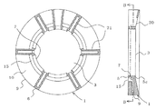
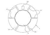
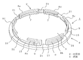
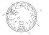
次に実施形態2について、図6乃至図10を用いて説明する。図6は本発明の実施の形態2に係る煙感知器のアダプタの斜視図、図7(a)は煙感知器にアダプタを取り付けた状態を示す平面図、図7(b)はその上面図、図7(c)は下面図、図7(d)は左側面図、図7(e)は右側面図である。図8は煙感知器にアダプタを取付けた状態を示す縦断面図である。図9は図8におけるアダプタ部分の一部拡大断面図である。図10は煙感知部の横断面図である。なお、実施の形態1と同じ部分又はほぼ同じ機能の部分にはこれと同じ符号を付し、一部の説明を省略する。この実施の形態2は、流出口と流入口を近接させ、両者の間に形成される流路の長さをほとんどなくした点が実施の形態1との違いの一つである。
[Embodiment 2]
Next, Embodiment 2 will be described with reference to FIGS. 6 is a perspective view of the adapter of the smoke detector according to the second embodiment of the present invention, FIG. 7A is a plan view showing a state where the adapter is attached to the smoke detector, and FIG. 7B is a top view thereof. 7C is a bottom view, FIG. 7D is a left side view, and FIG. 7E is a right side view. FIG. 8 is a longitudinal sectional view showing a state in which the adapter is attached to the smoke detector. FIG. 9 is a partially enlarged sectional view of the adapter portion in FIG. FIG. 10 is a cross-sectional view of the smoke detector. Note that portions that are the same as or substantially the same in function as those of the first embodiment are denoted by the same reference numerals, and a part of the description is omitted. The second embodiment is one of the differences from the first embodiment in that the outflow port and the inflow port are brought close to each other and the length of the flow path formed between the two is almost eliminated.

図において、1は樹脂などで成型されたアダプタで、円筒部2とその下端部外周に設けた鍔部4によりほぼドーナツ状に形成されており、円筒部2の内径(嵌合穴3の内径)は、煙感知部31の外径とほぼ等しい大きさに形成されている。
円筒部2には、煙感知器30のカバー32に設けたフィンFに対応して嵌合溝21が設けられ、複数(図には6個の場合を示してある)に分割されている。そして、分割された各円筒部8a〜8f(以下、分割縦壁という)には、それぞれ流入口9及び流出口7が開口している。アダプタ1の円筒部2に設けた嵌合溝21は、円筒部2の上端から下端(鍔部4)にわたって設けられ、フィンFに嵌合しうる幅に形成されている。この嵌合溝21により取付手段が構成される。このような取付手段を設けることで、既設の煙感知器に対して、アダプタ1を容易に取り付けることが可能となる。また、鍔部4には各分割縦壁8a〜8fの基部、したがって、各流入口9に沿ってスリット状の水抜き穴15が設けられており、図8に示すように、流入口9と水抜き穴15との間にはこれらに連通する流出口7が設けられて、これらにより短い流路10が形成されている。
In the figure, reference numeral 1 denotes an adapter molded of resin or the like, which is formed in a substantially donut shape by a cylindrical portion 2 and a flange 4 provided on the outer periphery of the lower end portion thereof. ) Is formed to have a size substantially equal to the outer diameter of the smoke sensing unit 31.
The cylindrical portion 2 is provided with fitting grooves 21 corresponding to the fins F provided on the cover 32 of the smoke detector 30, and is divided into a plurality (six cases are shown in the figure). And the inflow port 9 and the outflow port 7 are opening to each cylindrical part 8a-8f (henceforth a division | segmentation vertical wall) divided | segmented. The fitting groove 21 provided in the cylindrical portion 2 of the adapter 1 is provided from the upper end to the lower end (the flange portion 4) of the cylindrical portion 2 and is formed to have a width that can be fitted into the fin F. The fitting groove 21 constitutes an attaching means. By providing such attachment means, the adapter 1 can be easily attached to the existing smoke detector. Further, the flange 4 is provided with slit-like drain holes 15 along the bases of the respective divided vertical walls 8a to 8f, and hence along the respective inflow ports 9, and as shown in FIG. An outlet 7 communicating with these is provided between the drain hole 15 and a short flow path 10 is formed by these.

この流路10についてさらに説明する。流路10は実施の形態1で説明したように、湯気の流入の防止を考慮すると、高さの低い偏平な形状が望まれる。このため図7(e)に示す例えば分割縦壁8cの流入口9は、上下の幅が狭く(細く)形成されて開口面積が小さくなっている。湯気の流入の防止だけを考慮すれば、他の分割縦壁(例えば、8a,8b,8d〜8f)の流入口9も、分割縦壁8cの流入口9と同じ幅にしてもよいが、ここでは、煙感知部31内に360度どの方向からもほぼ均等に煙が流入するように、流入口9の形状及び嵌合溝21の幅をかえてある。即ち、分割縦壁8aと分割縦壁8fの間の嵌合溝21は非常に大きく形成し、それに続いて分割縦壁8cと分割縦壁8dの間にある嵌合溝21も比較的大きく形成してある。またそれ以外の嵌合溝21についてはフィンFとほぼ同じ幅に形成してある(図7参照)。これは以下のためである。   The flow path 10 will be further described. As described in Embodiment 1, the flow channel 10 is desired to have a flat shape with a low height in consideration of prevention of inflow of steam. For this reason, for example, the inlet 9 of the divided vertical wall 8c shown in FIG. 7 (e) has a narrow vertical width (thinner) and a small opening area. If only the prevention of steam inflow is considered, the inlet 9 of the other divided vertical walls (for example, 8a, 8b, 8d to 8f) may have the same width as the inlet 9 of the divided vertical wall 8c. Here, the shape of the inflow port 9 and the width of the fitting groove 21 are changed so that the smoke flows into the smoke detection unit 31 almost uniformly from any direction of 360 degrees. That is, the fitting groove 21 between the divided vertical wall 8a and the divided vertical wall 8f is formed very large, and subsequently, the fitting groove 21 between the divided vertical wall 8c and the divided vertical wall 8d is also formed relatively large. It is. The other fitting grooves 21 are formed to have substantially the same width as the fins F (see FIG. 7). This is for the following.

例えば、図10に示すように、煙感知部31において、発光素子、受光素子を収納した収納部45,46の背面(外周側)には縦壁が設けられて、他の箇所よりも煙が流入しにくい。このため、この収納部45,46の位置に対応する嵌合溝21の幅を他よりも広く形成することで、煙を流入し易くしてある(図6、図7(b),(c))。なお、各流出口7は、発光素子と受光素子を結ぶ光軸36(図9参照)より低い位置に設けられている。ここで、分割縦壁8a〜8fの形状について説明する。分割縦壁8b,8eは左右両端部に柱があり、両端部は閉じられているが、分割縦壁8a,8c,8d,8fは左右いずれかにのみ柱があり、片側が開いている形状になっている。なお、分割縦壁8a,8c,8d,8fには、流出口7のほぼ中間部に補強用の柱が設けられている。   For example, as shown in FIG. 10, in the smoke detection unit 31, vertical walls are provided on the back surfaces (outer peripheral sides) of the storage units 45 and 46 that store the light emitting element and the light receiving element, and smoke is emitted from other portions. Difficult to flow in. For this reason, by making the width of the fitting groove 21 corresponding to the positions of the storage portions 45 and 46 wider than the others, it is easy for smoke to flow in (FIGS. 6, 7B, and 6C). )). Each outlet 7 is provided at a position lower than the optical axis 36 (see FIG. 9) connecting the light emitting element and the light receiving element. Here, the shape of the divided vertical walls 8a to 8f will be described. The divided vertical walls 8b and 8e have columns at both left and right ends, and both ends are closed, but the divided vertical walls 8a, 8c, 8d, and 8f have columns only on either the left and right sides, and one side is open. It has become. The split vertical walls 8a, 8c, 8d, and 8f are provided with reinforcing columns substantially at the intermediate portion of the outlet 7.

次に、本実施の形態に係るアダプタ1の作用につき、まず、図9により、煙感知器30の近辺で火災が発生し、煙が生じた場合について説明する。火災時の煙(実線で示す)は、前述のように天井下面に沿って水平方向に流れ、その一部は流入口9から流入し流路10に流れる。煙は上昇するように流れるから流路10を通る際、水抜き穴15からほとんど流出することなく、大部分が流出口7及び煙流入口35を通って煙感知部31に到達することになる。   Next, the operation of the adapter 1 according to the present embodiment will be described with reference to FIG. 9 in the case where a fire is generated near the smoke detector 30 and smoke is generated. Smoke at the time of fire (shown by a solid line) flows in the horizontal direction along the lower surface of the ceiling as described above, and part of the smoke flows from the inlet 9 and flows into the flow path 10. Since smoke flows upward, when passing through the flow path 10, most of the smoke reaches the smoke detector 31 through the outlet 7 and the smoke inlet 35 with almost no outflow from the drain hole 15. .

次に、図9により、煙感知器30の近傍において、風呂場や湯沸かし器等から湯気が発生する場合について説明する。前述のように湯気(破線で示す)が天井面に立ち上ると、煙と同様にアダプタ1の流入口9から流入する。この時、アダプタ1の鍔部4が外側に突き出ており、また流入口9の高さhが低いことから、流入口9からほぼ水平に流入する湯気は、流路10を通る際、流路10の上方の壁面に付着して水滴となり、また流入口9から斜め下方に流れ込む湯気の一部は、流路10を通る際、流路の下方の壁面に付着して水滴となる。これら壁面に付着した水滴は、水抜き穴15から排出される。一方、斜め下方に流れ込んだ湯気の一部は、流出口7から煙感知部31に流入するが、湯気は煙粒子より粒子径が大きく、質量が大きいため、煙感知部31の内において上昇することなく、煙感知部31の底部に付着するか又は蒸発することになる。このように、アダプタ1において湯気が斜め上方に向って流入しないように、流入口9と流出口7の位置がきめられている。   Next, a case where steam is generated from a bathroom, a water heater or the like in the vicinity of the smoke detector 30 will be described with reference to FIG. As described above, when steam (shown by a broken line) rises on the ceiling surface, it flows from the inlet 9 of the adapter 1 like smoke. At this time, since the flange portion 4 of the adapter 1 protrudes outward and the height h of the inlet 9 is low, steam flowing in substantially horizontally from the inlet 9 A portion of the steam that adheres to the upper wall surface 10 and forms water droplets and flows obliquely downward from the inflow port 9 adheres to the lower wall surface of the flow channel and forms water droplets when passing through the flow channel 10. Water droplets adhering to these wall surfaces are discharged from the drain hole 15. On the other hand, a part of the steam that flows obliquely downward flows into the smoke sensing unit 31 from the outlet 7, but the steam rises in the smoke sensing unit 31 because the particle size and mass are larger than the smoke particles. Without adhering to the bottom of the smoke sensing part 31, it will evaporate. Thus, the positions of the inflow port 9 and the outflow port 7 are determined so that steam does not flow obliquely upward in the adapter 1.

本実施の形態においては、アダプタ1の流路10を短く形成したが、流出口7を発光素子の光軸(図9の36)より低い位置に設けてあり、また、湯気はほとんど上昇することがないので、煙感知部31内に湯気が浸入しても発光素子と受光素子を結ぶ光軸36に達する量が減り、湯気による誤報を防止することができる。   In the present embodiment, the flow path 10 of the adapter 1 is formed short, but the outlet 7 is provided at a position lower than the optical axis of the light emitting element (36 in FIG. 9), and the steam almost rises. Therefore, even if steam enters the smoke sensing unit 31, the amount reaching the optical axis 36 connecting the light emitting element and the light receiving element is reduced, and erroneous reporting due to steam can be prevented.

本実施の形態においても実施の形態1の場合とほぼ同様の効果を得ることができるが、さらに、アダプタ1に鍔部4を設けたので、流入口9への煙の流入を促進すると共に、湯気が鍔部4に当って水滴になるため、流入口9からの湯気の流入を低減することができる。また、流入口9と流出口7を連通する流路10を可及的に短くしたので、アダプタ1を小形化することができる。   In the present embodiment, it is possible to obtain substantially the same effect as in the case of the first embodiment, but furthermore, since the flange portion 4 is provided in the adapter 1, it facilitates the inflow of smoke into the inflow port 9, Since the steam hits the collar 4 to form water droplets, the inflow of steam from the inlet 9 can be reduced. Moreover, since the flow path 10 which connects the inflow port 9 and the outflow port 7 is made as short as possible, the adapter 1 can be reduced in size.

上記の説明では、本発明に係るアダプタ1を既設の煙感知器30に装着する場合について述べたが、新設の煙感知器30にも本発明に係るアダプタ1を装着しうることは言うまでもない。   In the above description, the case where the adapter 1 according to the present invention is attached to the existing smoke detector 30 has been described, but it goes without saying that the adapter 1 according to the present invention can also be attached to the new smoke detector 30.

(a)は本発明の実施の形態1に係るアダプタの平面図、(b)はアダプタの側面図である。(A) is a top view of the adapter which concerns on Embodiment 1 of this invention, (b) is a side view of an adapter. 図1のアダプタを煙感知器に取り付けた状態の縦断面図である。It is a longitudinal cross-sectional view of the state which attached the adapter of FIG. 1 to the smoke detector. (a)は図1のA−A断面図、(b)は図3(a)のB−B断面図である。(A) is AA sectional drawing of FIG. 1, (b) is BB sectional drawing of Fig.3 (a). アダプタを煙感知器取付側から見た平面図である。It is the top view which looked at the adapter from the smoke detector attachment side. アダプタの斜視図である。It is a perspective view of an adapter. 本発明の実施の形態2に係るアダプタの斜視図である。It is a perspective view of the adapter which concerns on Embodiment 2 of this invention. (a)は図6のアダプタを煙感知器に取り付けた状態を示す平面図、(b)はその上面図、(c)は下面図、(d)は左側面図、(e)は右側面図である。(A) is a plan view showing a state where the adapter of FIG. 6 is attached to the smoke detector, (b) is a top view thereof, (c) is a bottom view, (d) is a left side view, and (e) is a right side view. FIG. 図6のアダプタを煙感知器に取付けた状態の縦断面図である。It is a longitudinal cross-sectional view of the state which attached the adapter of FIG. 6 to the smoke detector. 実施の形態2のアダプタの作用説明図である。FIG. 10 is an operation explanatory diagram of the adapter of the second embodiment. 煙感知部の横断面図である。It is a cross-sectional view of a smoke detector.

符号の説明Explanation of symbols

1 アダプタ、2 円筒部、3 嵌合穴、4 鍔部、5 内周縁部、5c 上部、6 外周面、7 流出口、9 流入口、10 流路、11 水平流路、12 下り流路、13 傾斜流路、15 水抜き穴、16 底面、20 投光窓、21 嵌合溝、30 煙感知器、31 煙感知部、32 カバー、33 防虫網、35 煙流入口、36 光軸、37 確認灯。
DESCRIPTION OF SYMBOLS 1 Adapter, 2 cylindrical part, 3 fitting hole, 4 collar part, 5 inner peripheral part, 5c upper part, 6 outer peripheral surface, 7 outflow port, 9 inflow port, 10 flow path, 11 horizontal flow path, 12 downstream flow path, 13 Inclined channel, 15 Drain hole, 16 Bottom, 20 Floodlight window, 21 Fitting groove, 30 Smoke detector, 31 Smoke detector, 32 Cover, 33 Insect net, 35 Smoke inlet, 36 Optical axis, 37 Confirmation light.

Claims (8)

煙感知器の煙感知部の外周に取り付けられる煙感知器のアダプタであって、
前記煙感知器の煙流入口に対向して設けられる流出口と、前記流出口と流路を介して設けられる流入口とを前記アダプタに設けたことを特徴とする煙感知器のアダプタ。
A smoke detector adapter attached to the outer periphery of the smoke detector of the smoke detector,
An adapter for a smoke detector, wherein the adapter includes an outlet provided opposite to a smoke inlet of the smoke detector, and an inlet provided via the outlet and a flow path.
前記アダプタに下方に開口した水抜き穴を設け、該水抜き穴と前記流路を連通したことを特徴とする請求項1記載の煙感知器のアダプタ。   2. The smoke sensor adapter according to claim 1, wherein a water drain hole that opens downward is provided in the adapter, and the water drain hole communicates with the flow path. 前記流路を、高さの低い偏平な形状にしたことを特徴とする請求項1記載の煙感知器のアダプタ。   2. The smoke sensor adapter according to claim 1, wherein the flow path has a flat shape with a low height. 前記水抜き穴の一部を覆うか又は塞ぐことを特徴とする請求項2記載の煙感知器のアダプタ。   3. The smoke sensor adapter according to claim 2, wherein a part of the drain hole is covered or closed. 前記流路は、前記流入口から内側に延びた水平流路と、該水平流路から下方へ延びた下り流路と、該下り流路の途中から前記流出口へ上がる傾斜流路とから形成されることを特徴とする請求項1乃至請求項4のいずれかに記載の煙感知器のアダプタ。   The flow path is formed of a horizontal flow path extending inward from the inlet, a downward flow path extending downward from the horizontal flow path, and an inclined flow path rising from the middle of the downward flow path to the outlet. The smoke sensor adapter according to any one of claims 1 to 4, wherein the smoke sensor adapter is provided. 前記下り流路は、前記水平流路から前記水抜き穴へ向かって下方へ延びていることを特徴とする請求項5記載の煙感知器のアダプタ。   6. The smoke sensor adapter according to claim 5, wherein the down flow path extends downward from the horizontal flow path toward the drain hole. 前記煙感知部は、一対の発光素子及び受光素子を有し、前記流出口は、前記発光素子と受光素子をむすぶ光軸よりも低い位置に設けられることを特徴とする請求項1記載の煙感知器のアダプタ。   2. The smoke according to claim 1, wherein the smoke sensing unit has a pair of a light emitting element and a light receiving element, and the outlet is provided at a position lower than an optical axis extending between the light emitting element and the light receiving element. Sensor adapter. 前記煙感知器のカバーに複数本のフィンを設け、該フィンに嵌合する取付手段をアダプタに設けたことを特徴とする請求項1記載の煙感知器のアダプタ。
2. The smoke sensor adapter according to claim 1, wherein a plurality of fins are provided on the cover of the smoke sensor, and attachment means for fitting the fins is provided on the adapter.
JP2004306873A 2004-03-09 2004-10-21 Smoke detector adapter Expired - Fee Related JP4258734B2 (en)

Priority Applications (1)

Application Number Priority Date Filing Date Title
JP2004306873A JP4258734B2 (en) 2004-03-09 2004-10-21 Smoke detector adapter

Applications Claiming Priority (2)

Application Number Priority Date Filing Date Title
JP2004066442 2004-03-09
JP2004306873A JP4258734B2 (en) 2004-03-09 2004-10-21 Smoke detector adapter

Publications (2)

Publication Number Publication Date
JP2005293548A true JP2005293548A (en) 2005-10-20
JP4258734B2 JP4258734B2 (en) 2009-04-30

Family

ID=35326369

Family Applications (1)

Application Number Title Priority Date Filing Date
JP2004306873A Expired - Fee Related JP4258734B2 (en) 2004-03-09 2004-10-21 Smoke detector adapter

Country Status (1)

Country Link
JP (1) JP4258734B2 (en)

Cited By (3)

* Cited by examiner, † Cited by third party
Publication number Priority date Publication date Assignee Title
JP2010238087A (en) * 2009-03-31 2010-10-21 Nohmi Bosai Ltd Photoelectric smoke sensor
JP2011210213A (en) * 2010-03-31 2011-10-20 Nohmi Bosai Ltd Photoelectric smoke sensor
WO2021215460A1 (en) * 2020-04-21 2021-10-28 パナソニックIpマネジメント株式会社 Detector

Cited By (6)

* Cited by examiner, † Cited by third party
Publication number Priority date Publication date Assignee Title
JP2010238087A (en) * 2009-03-31 2010-10-21 Nohmi Bosai Ltd Photoelectric smoke sensor
JP2011210213A (en) * 2010-03-31 2011-10-20 Nohmi Bosai Ltd Photoelectric smoke sensor
WO2021215460A1 (en) * 2020-04-21 2021-10-28 パナソニックIpマネジメント株式会社 Detector
JPWO2021215460A1 (en) * 2020-04-21 2021-10-28
EP4141833A4 (en) * 2020-04-21 2023-10-11 Panasonic Intellectual Property Management Co., Ltd. Detector
JP7394360B2 (en) 2020-04-21 2023-12-08 パナソニックIpマネジメント株式会社 Detector and fire alarm system

Also Published As

Publication number Publication date
JP4258734B2 (en) 2009-04-30

Similar Documents

Publication Publication Date Title
US7697140B2 (en) Photoelectric smoke detector
JP4910179B2 (en) Flow sensor
JP4258734B2 (en) Smoke detector adapter
JP5191355B2 (en) Fire detector
JPH10154283A (en) Fire sensor
JP5036597B2 (en) smoke detector
CN110168322B (en) Photoelectric smoke detector with double-partition darkroom structure
JP2016099733A (en) Photoelectric smoke detector
AU2008264607B2 (en) Smoke sensor
JP4881676B2 (en) Thermal flow meter
JP6453048B2 (en) Detector
JP2005128871A (en) Fire detector
JP7237155B2 (en) physical quantity detector
JP4650455B2 (en) smoke detector
JP5325397B2 (en) smoke detector
JP2009211327A (en) Lighting device and smoke sensor
JP5490366B2 (en) smoke detector
JPH07245006A (en) Lamp for vehicle
US20160069060A1 (en) Urinal
JP5784956B2 (en) Alarm
JP5490367B2 (en) smoke detector
JP2009199518A (en) Smoke detector
JP2020071140A5 (en)
JP2002168474A (en) Drain water disposer of air conditioner
JPH0143636Y2 (en)

Legal Events

Date Code Title Description
A621 Written request for application examination

Free format text: JAPANESE INTERMEDIATE CODE: A621

Effective date: 20060926

A977 Report on retrieval

Free format text: JAPANESE INTERMEDIATE CODE: A971007

Effective date: 20080724

A131 Notification of reasons for refusal

Free format text: JAPANESE INTERMEDIATE CODE: A131

Effective date: 20080805

A521 Written amendment

Free format text: JAPANESE INTERMEDIATE CODE: A523

Effective date: 20081003

A131 Notification of reasons for refusal

Free format text: JAPANESE INTERMEDIATE CODE: A131

Effective date: 20081104

A521 Written amendment

Free format text: JAPANESE INTERMEDIATE CODE: A523

Effective date: 20081215

TRDD Decision of grant or rejection written
A01 Written decision to grant a patent or to grant a registration (utility model)

Free format text: JAPANESE INTERMEDIATE CODE: A01

Effective date: 20090120

A01 Written decision to grant a patent or to grant a registration (utility model)

Free format text: JAPANESE INTERMEDIATE CODE: A01

A61 First payment of annual fees (during grant procedure)

Free format text: JAPANESE INTERMEDIATE CODE: A61

Effective date: 20090128

FPAY Renewal fee payment (event date is renewal date of database)

Free format text: PAYMENT UNTIL: 20120220

Year of fee payment: 3

R150 Certificate of patent or registration of utility model

Ref document number: 4258734

Country of ref document: JP

Free format text: JAPANESE INTERMEDIATE CODE: R150

Free format text: JAPANESE INTERMEDIATE CODE: R150

FPAY Renewal fee payment (event date is renewal date of database)

Free format text: PAYMENT UNTIL: 20120220

Year of fee payment: 3

FPAY Renewal fee payment (event date is renewal date of database)

Free format text: PAYMENT UNTIL: 20130220

Year of fee payment: 4

FPAY Renewal fee payment (event date is renewal date of database)

Free format text: PAYMENT UNTIL: 20130220

Year of fee payment: 4

FPAY Renewal fee payment (event date is renewal date of database)

Free format text: PAYMENT UNTIL: 20140220

Year of fee payment: 5

LAPS Cancellation because of no payment of annual fees