JP2005293521A - Method and device for removing unnecessary part of image - Google Patents
Method and device for removing unnecessary part of image Download PDFInfo
- Publication number
- JP2005293521A JP2005293521A JP2004130439A JP2004130439A JP2005293521A JP 2005293521 A JP2005293521 A JP 2005293521A JP 2004130439 A JP2004130439 A JP 2004130439A JP 2004130439 A JP2004130439 A JP 2004130439A JP 2005293521 A JP2005293521 A JP 2005293521A
- Authority
- JP
- Japan
- Prior art keywords
- area
- unnecessary
- image
- search
- region
- Prior art date
- Legal status (The legal status is an assumption and is not a legal conclusion. Google has not performed a legal analysis and makes no representation as to the accuracy of the status listed.)
- Pending
Links
- 238000000034 method Methods 0.000 title claims description 39
- 238000004364 calculation method Methods 0.000 claims abstract description 21
- 239000010893 paper waste Substances 0.000 claims 1
- 238000012545 processing Methods 0.000 abstract description 75
- 238000010586 diagram Methods 0.000 description 11
- 239000000463 material Substances 0.000 description 8
- 230000015572 biosynthetic process Effects 0.000 description 3
- 238000006243 chemical reaction Methods 0.000 description 3
- 238000002360 preparation method Methods 0.000 description 3
- 230000000694 effects Effects 0.000 description 2
- 238000012805 post-processing Methods 0.000 description 2
- 230000032683 aging Effects 0.000 description 1
- 230000001419 dependent effect Effects 0.000 description 1
- 238000011156 evaluation Methods 0.000 description 1
- 230000006870 function Effects 0.000 description 1
- 238000004519 manufacturing process Methods 0.000 description 1
- 239000000203 mixture Substances 0.000 description 1
- 238000003672 processing method Methods 0.000 description 1
Images

Landscapes
- Image Processing (AREA)
Abstract
Description
本発明は、対象とする画像の撮影時に不要物が混在した場合に、後処理として不要物を除くための画像信号処理の方法および装置に関する。The present invention relates to an image signal processing method and apparatus for removing unnecessary objects as post-processing when unnecessary objects are mixed when a target image is captured.
従来より画像修復は貴重な写真か経年変化して劣化したものや、傷などで劣化したもの、撮影時の条件が悪くて不要物が対象物の前にあって、対象物を隠蔽している場合などに対して試みられて来たが、完全な修復は難しかった。Traditionally, image restoration is precious or has deteriorated due to aging, or has deteriorated due to scratches, etc., shooting conditions are bad and unnecessary objects are in front of the object, hiding the object Attempts have been made for cases, but complete restoration has been difficult.
特許文献1はディジタル画像からスクラッチまたはワイヤ雑音を除去する方式を開示している。修復又は雑音除去を必要とするスクラッチが判別されディジタル画像の他の部分からその判別されたスクラッチの場所を区別するバイナリマスクが生成されたディジタル画像から、スクラッチ又はワイヤノイズを除去する。スクラッチや他の雑音の修復を必要とするディジタル画像の場所を示すリペアサブイメージが定義される。サンプルイメージは、リペアイメージにできるだけ似るように選択される。しかし、類似度の探索を高速フーリエ変換領域で行っているため、周波数成分の一致性を重視する結果、輝度成分の不一致の問題がある。また、サンプルイメージの使用やソフトエッジ処理の導入により、原画像との乖離が進むという問題点もあった。また、全体の輝度又はリペアサブイメージとリペアサブイメージの輝度の低速変化はそれぞれ異なることがある。
非特許文献1は正方形状の不要物領域を高次の線形加算近似画像で近似する画像処理(FID法)を行い、正方形状の領域の不要物除去が行えることを示している。この方式では、不要物領域に対する修復領域の生成のために、高次の線形加算演算を反復的に行い、最も類似した修復領域を求める。
しかしながら、非特許文献2では不要物領域の修復に高次の線形加算演算FID法を反復的に行わなければならないため、演算処理量が膨大になり、実用的な時間内に演算処理を行うことは当面難しい状況になっている。高次の多大な未知数を含む線形結合関数の最適化を図るため、与える条件から最適解を求めることが難しくなる場合もある。However, in Non-Patent Document 2, since the high-order linear addition operation FID method must be repeatedly performed to repair the unnecessary region, the amount of operation processing becomes enormous, and the operation processing is performed within a practical time. The situation is difficult for the time being. In order to optimize a linear combination function including a large number of high-order unknowns, it may be difficult to obtain an optimal solution from given conditions.
そこで、本発明の第一の課題は、画像中に電線などの不要物が上書きされている時に、電線を除くとともに、違和感のない修復画像を求める実用化可能なアルゴリズムを与えることである。違和感のない修復画像で不要物領域周辺を置き換え、置き換えた小領域の修復画像の境界が目立つことなく自然なつながりのある修復画像を求めることが重要である。Therefore, a first problem of the present invention is to provide an algorithm that can be put into practical use for removing a wire and obtaining a repair image without a sense of incongruity when an unnecessary object such as a wire is overwritten in the image. It is important to replace the periphery of the unwanted object region with a repaired image that does not give a sense of incongruity, and to obtain a repaired image having a natural connection without making the boundary of the repaired image of the replaced small region noticeable.
本発明の第二の課題は、修復画像を求めるための演算時間を削減することにある。例えば、1枚の静止画像に対し、数分程度で修復画像を生成するための方式を提供することが重要である。このため、電線除去の修復画像特有のブロックパターンを形成し、演算の高速化を図る必要がある。A second problem of the present invention is to reduce the calculation time for obtaining a repaired image. For example, it is important to provide a method for generating a repair image in about several minutes for one still image. For this reason, it is necessary to form a block pattern peculiar to the repaired image for removing the electric wire to increase the calculation speed.
本発明の第三の課題は、不要物が直線状の単純な形状ではなく、曲がった曲線や、複数の曲線である場合に高速な処理時間で、視覚的にほぼ違和感のない修復画像を生成することである。The third problem of the present invention is to generate a repaired image that is visually inconspicuous in high-speed processing time when the unnecessary object is not a straight simple shape but a curved curve or a plurality of curves. It is to be.
上記課題を解決するため、本発明ではまず、入力画像の中から、不要物を特定した後不要物部分は、RGB式度値で(0,0,0)の黒色に置き換える処理を行なう。これに対応して、その他の部分に(0,0,0)の値の式度値が存在していた場合は、(1,0,0)などの別の値に変換しておく。これにより、不要物を示すマスク領域のデータを特許文献1のように、別途指定して用意する必要がなくなる。また,電線などの長く連続する不要物を除去するときには,非特許文献2のように,不要物を取り囲むように領域を形成することはできない。そこで、不要物を短い小領域に分割するとともに、横線状の場合ならば、上下に拡張した挟領域を形成し、左右は包み込まない形にすることによって、左右に連続した除去処理を継続していくことができる。不要物が長く伸びている場合は不要物を包み込む形に領域を設定することはできない。In order to solve the above-described problem, in the present invention, first, after an unnecessary object is specified from the input image, the unnecessary object portion is replaced with black of (0, 0, 0) with RGB degree values. Correspondingly, if there is an expression value of (0, 0, 0) in the other part, it is converted to another value such as (1, 0, 0). This eliminates the need to separately designate and prepare mask area data indicating an unnecessary object as in Japanese Patent Application Laid-Open No. 2004-133830. In addition, when removing unnecessary long continuous objects such as electric wires, a region cannot be formed so as to surround the unnecessary objects as in Non-Patent Document 2. Therefore, the unnecessary object is divided into short small areas, and in the case of a horizontal line, by forming a sandwiched area extending up and down and not wrapping the left and right, continuous removal processing on the left and right is continued. I can go. When an unnecessary object extends for a long time, the area cannot be set so as to wrap the unnecessary object.
また、画像の不要物の領域と修復画像を探索する際に、不要物を含む挟領域の形状は同一の形状である必要はなく、任意の形状で、また挟領域ごとに異なる形状になっていてもマスクデータを用意することなく、高速に探索をすすめることが出来る。マスク領域は、挟領域の黒値の画素か否かで判別でき、マスクデータを参照する手続きが省略できる。また、電線は、画面中に水平に延びているとは限らず、一般には斜め上方または斜め下方に延びている。そのため、不要物を含む挟領域は位置により同一の長方形で囲むことが出来るとは限らず、サイズの異なる長方形を場所ごとに設定する必要がある。このため、不要物を含む挟領域を黒色値で指定して、サイズの異なる長方形を場所ごとに設定することを行なう。In addition, when searching for an unnecessary object area and a repair image in an image, the shape of the sandwiched area including the unnecessary object does not need to be the same shape, and is an arbitrary shape and is different for each sandwiched area. However, the search can be performed at high speed without preparing mask data. The mask area can be determined based on whether or not it is a black value pixel in the sandwiched area, and the procedure for referring to the mask data can be omitted. Moreover, the electric wire does not necessarily extend horizontally in the screen, and generally extends obliquely upward or obliquely downward. For this reason, it is not always possible to enclose the sandwiched area including unnecessary objects with the same rectangle depending on the position, and it is necessary to set rectangles of different sizes for each location. For this reason, a sandwiching area including unnecessary objects is designated by a black value, and rectangles having different sizes are set for each location.
次に請求項2の課題を解決するため、まず、入力画像の中から、不要物を特定した後不要物部分は、RGB式度値で(0,0,0)の黒色に置き換える処理を行なう。電線などの不要物がある場合、電線は、画面中に水平に延びているとは限らず、一般には斜め上方または斜め下方に延びている。これに対応して不要物を含む挟領域は不要物の傾斜と−致した傾斜を持つ凸集合を用意する。ひとつの挟集合の探索を行なう時、探索の計算結果を保持し、次に例えば画面右側に挟領域をずらす場合、前記計算結果のうちずらして重なった部分の結果をそのまま使用し、新たに右から追加された部分のみ計算を追加する。一方、左側でずらして不要になった部分の計算結果は差し引いておく。ずらす画素数は1画素から挟領域の横幅野長さまで、任意に設定できる。Next, in order to solve the problem of claim 2, first, after an unnecessary object is specified from the input image, the unnecessary object portion is replaced with black of (0, 0, 0) with an RGB formula value. . When there is an unnecessary object such as an electric wire, the electric wire does not necessarily extend horizontally in the screen, and generally extends obliquely upward or obliquely downward. Correspondingly, a convex set having a slope that matches the slope of the unwanted object is prepared for the sandwiched area containing the unwanted object. When searching for one sandwiched set, hold the calculation result of the search, and then shift the sandwiched area to the right side of the screen, for example, use the result of the overlapped portion of the calculation result as it is, and add a new right Add calculation only for the part added from. On the other hand, the calculation result of the portion that is no longer necessary by shifting on the left side is subtracted. The number of pixels to be shifted can be arbitrarily set from 1 pixel to the horizontal width of the sandwiched area.
次に請求項3の課題を解決するため、不要物のマスク領域を処理する画像内に埋め込み黒値にすることにより、識別し、これを左から右、上から下に探索することにより、高速で、もれなく挟領域を連続的に形成できる。なお、探索の方向は右から左や下から上にしても同様な結果が得られるので、可能な方向は上記左から右、上から下だけではない。Next, in order to solve the problem of claim 3, an unnecessary object mask area is identified by embedding it in an image to be processed into a black value, and this is searched for from left to right and from top to bottom. Thus, the sandwiched area can be formed continuously without any leakage. Note that the same result can be obtained even if the search direction is from right to left or from bottom to top, so the possible directions are not limited to the above left to right and top to bottom.
また、これらの処理によりもともと存在していない不要物によって隠蔽されていた部分が復元され、違和感のない画像になるのは、自然画像の持つフラクタル性に依存している。フラクタル性のない画像においては、本手法は性能が劣化したり、除去が不十分であることもあるが、通常の風景画像などの自然画像では、本発明の処理に必要なフラクタル性を有している。In addition, it is dependent on the fractal nature of the natural image that the part concealed by the unnecessary object that does not exist is restored by these processes, and the image does not feel strange. For images that do not have fractal properties, the performance of this method may deteriorate or may be insufficiently removed, but natural images such as ordinary landscape images have the fractal properties necessary for the processing of the present invention. ing.
発明の実施形態:
以下、本発明の実施の諸形態について図面を参照して説明する。まず、図1等参照して、本発明の実施形態に係わる不要部分の除去方法及び除去装置について説明する。Embodiments of the invention:
Hereinafter, embodiments of the present invention will be described with reference to the drawings. First, with reference to FIG. 1 etc., the removal method and removal apparatus of the unnecessary part concerning embodiment of this invention are demonstrated.
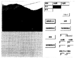
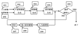
図1は、本発明の実施形態に係わる不要部分の除去装置の動作画面の例である。図2はその処理動作の構成を示すブロック図である。入力画像201は処理により修復される画像データで、参照画像202はその初期状態と同じ画像データで、以後の処理で変更されないデータである。不要物領域生成処理部203電線などの不要物領域部分が操作者のマウス操作などにより指示され、決定される。不要物領域生成データは挟領域生成処理部204に送られ、不要物を含む挟領域が生成される。FIG. 1 is an example of an operation screen of an unnecessary portion removing apparatus according to an embodiment of the present invention. FIG. 2 is a block diagram showing the configuration of the processing operation. The
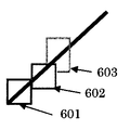
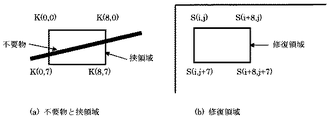
図4に挟領域の生成の詳細を示す。電線の場合、挟領域は、その傾きが0から45度の時、不要物である電線の上下に微小な画素を付加した領域が挟領域となる。また、不要物の傾斜が45から90度の時、不要物である電線の左右に微小な画素を付加した領域が挟領域となる。長い電線が、途中で曲がっている場合は、挟領域の形状は固定でなく、変化することもある。そこで、このように同一画面内の処理で、形状が変化する時、不要物領域に対しては、自由不要物領域、挟領域に対しては、自由挟領域と呼ぶことにする。自由小領域分割処理部402で一般には任意の小さい形状に分割する。分割上方に基づき挟領域生成処理部403で挟領域が清々さえる。挟領域の生成規則は、挟領域生成規則生成部404で生成された情報を基に形成され、使用される。挟領域は、長方形を使うことができるが、形状は任意でよく、凸多角形であれば、処理がし易い。FIG. 4 shows details of generation of the sandwiched area. In the case of an electric wire, when the inclination is 0 to 45 degrees, an area where minute pixels are added to the upper and lower sides of an unnecessary electric wire becomes the pinching area. When the inclination of the unwanted object is 45 to 90 degrees, the area where the minute pixels are added to the left and right of the unwanted wire is the sandwiched area. When a long electric wire is bent halfway, the shape of the sandwiched region is not fixed and may change. Thus, when the shape changes in the process within the same screen as described above, the unnecessary object area is referred to as a free unnecessary object area, and the sandwiched area is referred to as a free sandwiched area. In general, the free small area
挟領域データは探索領域生成処理部205に送られ、探索領域を生成する。探索領域は、少なくとも不要物の領域を含まないことが必要であり、これを除いたものが、基本の探索領域となる。図1の操作画面では、操作者が都合により探索範囲を縮小したい場合は、座標数値データやマウスの指示で、範囲を狭めることが出来るようになっている。これらの準備の後、ループ処理部206において挟領域ごとに探索を行い、全ての挟領域の処理が終了するまでは、NOのループを巡回し、全ての挟領域の処理が終了した後、YESの方へ処理が移り、終了となる。ループ内では、挟領域ごとに不要物領域を除いた部分の類似度が最も大きい領域を探索処理部207で探索範囲内から探し、誤差最小領域処理部208で誤差最小の領域を選択し、入力画像置換処理部209にて入力の置換を行なう。The sandwiched area data is sent to the search area
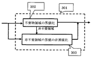
図3に不要物領域の生成の詳細を示す。不要物領域は別にマスク画像等を作ることなく、不要物を黒値(0,0,0)に変更する黒値化を不要物領域の黒値化処理部302で行なう。不要物領域部分を黒値化すると共に、それ以外の部分では黒値にならないようにするため、もし黒値のデータがあれば、非黒値に非不要領域の黒値の非黒値化処理部303で変更を行う。非黒値として、例えば、(1,0,0)を用いる。FIG. 3 shows details of the generation of the unwanted object region. The unnecessary value region black
本発明によれば、まず、従来の複雑な演算を簡易な差分方式で実現し、挟領域の形状を不要物を含み、かつ包み込まない形のより大きい挟領域とすることにより、傾いた直線や曲がった不要物に対しても現実的な処理時間内で処理が可能となった。また,包み込まない、挟領域を使うことによって細い線のような長い不要物に対しても連続的な処理が行なえる。不要物を回りから囲むことによって、挟領域が重なり、処理が不確定になるという問題を解決している。従来の不要物領域を示すマスク画像を別に作成し、参照していないため、マスク画像のメモリ容量、参照の手続き処理が不要となっている。実際本発明を実施した除去装置では、図8に示したように、不要物のうち指定した部分が完全に消去されたような画像が得られる。特許参考文献1のように周波数領域での処理は、ソフトエッジなどの処理が不要となる。According to the present invention, first, the conventional complicated calculation is realized by a simple difference method, and the shape of the sandwiched area is made into a larger sandwiched area that includes an unnecessary object and is not wrapped, Even bent unnecessary items can be processed within a realistic processing time. Moreover, continuous processing can be performed even for a long unnecessary object such as a thin line by using a sandwiched area that is not wrapped. By surrounding unnecessary objects from around, the problem that the sandwiched areas overlap and the processing becomes uncertain is solved. Since a conventional mask image indicating an unnecessary object area is separately created and not referenced, the memory capacity of the mask image and the reference procedure are not required. Actually, with the removing apparatus embodying the present invention, as shown in FIG. 8, an image is obtained in which the designated portion of the unnecessary object is completely erased. As in
また、第二の実施例においては、傾いた直線に対しても高速な連続的探索が行なえるため、処理時間が数十分の1に短縮できるという効果を実現した。このような演算を繰り返すことによって、探索の計算量が大幅に削減出来ることになる。これは主に直線状の不要物ないしは、区分的に直線状の不要物に対して有効である。Further, in the second embodiment, since a high-speed continuous search can be performed even with respect to an inclined straight line, an effect that the processing time can be shortened to 1 which is several tens of minutes has been realized. By repeating such calculation, the calculation amount of search can be greatly reduced. This is mainly effective for linear unnecessary objects or piecewise linear unnecessary objects.
また,第三の実施例においては、非直線上の曲がった不要物や複数の不要物が混在したものであっても除去が行なえる。Further, in the third embodiment, removal can be performed even for non-linearly bent unnecessary objects or a mixture of a plurality of unnecessary objects.
図1は、本発明の実施形態に係わる不要部分の除去装置の動作画面の例である。図8に処理前の画像(a)と処理後の結果の画像(b)を示す。図8(a)は建物の写真に人工的に黒筋をいれた画像で、図8(b)は本発明による方法にて、この黒筋を除去したものである。図2はその処理動作の構成を示すブロック図である。入力画像201は処理により修復される画像データで、参照画像202はその初期状態と同じ画像データで、以後の処理で変更されないデータである。不要物領域生成処理部203では電線などの不要物領域部分が操作者のマウス操作などにより指示され、決定される。FIG. 1 is an example of an operation screen of an unnecessary portion removing apparatus according to an embodiment of the present invention. FIG. 8 shows an image (a) before processing and an image (b) as a result after processing. FIG. 8A is an image in which black stripes are artificially added to a photograph of a building, and FIG. 8B is an image obtained by removing the black stripes by the method according to the present invention. FIG. 2 is a block diagram showing the configuration of the processing operation. The
図10(a)に不要物を3画素程度の固定の幅で指示した例を示す。不要物領域生成データは挟領域生成処理部204に送られ、不要物を含む挟領域が生成される。図10(a)に挟領域の例を示す。挟領域は任意の図形を用いることができるが、ここでは、横9画素、縦8画素の長方形を用いる場合について説明する。挟領域の長方形は、向かって左の辺の中央部に不要物の黒線が来るように設置する場合、傾きによって、下から1/3の位置に黒線が来るように設置する場合などがあるが、ここでは後者の例を示す。挟領域の画素配列をK(i,j)とし、ひとつの挟領域に対して、多数の修復候補領域を用いて探索を行なう。FIG. 10A shows an example in which an unnecessary object is designated with a fixed width of about 3 pixels. Unnecessary object region generation data is sent to the sandwiched region
図4に挟領域の生成の別の例の詳細を示す。電線の場合、挟領域は、その傾きが0から45度の時、不要物である電線の上下に微小な画素を付加した領域が挟領域となる。また、不要物の傾斜が45から90度の時、不要物である電線の左右に微小な画素を付加した領域が挟領域となる。長い電線が、途中で曲がっている場合は、挟領域の形状は固定でなく、変化することもある。そこで、このように同一画面内の処理で、形状が変化する時、不要物領域に対しては、自由不要物領域、挟領域に対しては、自由挟領域と呼ぶことにする。自由小領域分割処理部402で一般には任意の小さい形状に分割する。分割情報に基づき挟領域生成処理部403で挟領域が生成される。挟領域の生成規則は、挟領域生成規則生成部404で生成された情報を基に形成され、使用される。挟領域は、長方形を使うことができるが、形状は任意でよく、多角形等であれば、処理がし易い。FIG. 4 shows details of another example of generating the sandwiched area. In the case of an electric wire, when the inclination is 0 to 45 degrees, an area where minute pixels are added to the upper and lower sides of an unnecessary electric wire becomes the pinching area. When the inclination of the unwanted object is 45 to 90 degrees, the area where the minute pixels are added to the left and right of the unwanted wire is the sandwiched area. When a long electric wire is bent halfway, the shape of the sandwiched region is not fixed and may change. Thus, when the shape changes in the process within the same screen as described above, the unnecessary object area is referred to as a free unnecessary object area, and the sandwiched area is referred to as a free sandwiched area. In general, the free small area
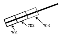
図6に長方形を主とした挟領域の例を示す。通常は電線の傾きは、小さいので、左から順に長方形で上下を挟んだ挟領域が形成されるが、この場合は傾きが45度以上あるため、不要物を上下からはさむ単純な長方形では、不要物領域を含む十分な挟領域の長方形は形成できない。そこで、ひとつ前の挟領域の境界に合せて、凹みのある6角形が用いられている。挟領域データは探索領域生成処理部205に送られ、探索領域を生成する。探索領域は、少なくとも不要物の領域を含まないことが必要であり、これを除いたものが、基本の探索領域となる。図1の操作画面では、操作者が都合により探索範囲を縮小したい場合は、座標数値データやマウスの指示で、範囲を指定することが出来るようになっている。これらの準備の後、ループ処理部206において挟領域ごとに修復領域の探索を行い、全ての挟領域の処理が終了するまでは、NOのループを巡回し、全ての挟領域の処理が終了した後、YESの方へ処理が移り、終了となる。ループ内では、挟領域ごとに不要物領域を除いた部分の修復領域で類似度が最も大きい修復領域を探索処理部207で探索範囲内から探し、誤差最小領域処理部208で誤差最小の領域を選択し、入力画像置換処理部209にて入力の置換を行なう。この時挟領域は探索された修復領域のデータに置き換えられる。類似度は、カラー画像のRGB3成分の値の差の絶対値または2乗和などを総和したものを用いれば良い。FIG. 6 shows an example of a sandwiching area mainly composed of rectangles. Normally, the inclination of the electric wire is small, so a sandwiched area is formed with a rectangle sandwiched from top to bottom in this order, but in this case the inclination is 45 degrees or more, so it is not necessary for a simple rectangle that sandwiches unwanted objects from above and below A rectangle with a sufficient sandwiching area including the object area cannot be formed. Therefore, a hexagon having a recess is used in accordance with the boundary of the previous sandwiched area. The sandwiched area data is sent to the search area
図3に不要物領域の生成の詳細を示す。不要物領域は別にマスク画像等を作ることなく、不要物を黒値(0,0,0)に変更する黒値化を不要物領域の黒値化処理部302で行なう。不要物領域部分を黒値化すると共に、それ以外の部分では黒値にならないようにするため、もし黒値のデータがあれば、非黒値に非不要領域の黒値の非黒値化処理部303で変更を行う。非黒値として、例えば、(1,0,0)を用いる。FIG. 3 shows details of the generation of the unwanted object region. The unnecessary value region black
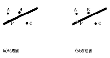
図5に黒値化と非黒値化の例を示す。図5(a)は黒値化処理前の説明図で、Pは不要物領域に含まれているが、黒値(0,0,0)でない、例えば(10,10,10)なる画素であり、黒値化によって、(0,0,0)に変更される。また、点A,B,Cは不要物領域外の周辺にある点で、いずれも黒値(0,0,0)になっている。これらの点は、不要物領域外である領域判定により、非黒値に変化する。非黒値の値として、例えば(1,0,0)や(0,1,0),(0,0,1)など用いることができる。これらの値は黒値ではないが、画像面では事実上、黒値に近いため、通常は黒値と区別することはできないと考えられる。FIG. 5 shows an example of blackening and non-blackening. FIG. 5A is an explanatory diagram before blackening processing, and P is included in an unnecessary object region, but is not a black value (0, 0, 0), for example, a pixel of (10, 10, 10). Yes, it is changed to (0, 0, 0) by blackening. Points A, B, and C are points outside the unnecessary object region, and all have black values (0, 0, 0). These points change to non-black values according to the area determination outside the unnecessary object area. As the non-black value, for example, (1, 0, 0), (0, 1, 0), (0, 0, 1) can be used. Although these values are not black values, they are practically close to black values on the image plane, and are usually considered indistinguishable from black values.
以下に探索の処理動作の各部分を簡易なプログラム言語で記述した例を示す。挟領域をH(i,j)、修復候補領域をS(i,j)、探索範囲を横10画素から590画素、縦10ラインから150ラインと縦300ラインから450ラインまでの2つの長方形とする。また、挟領域の長方形の開始点をis,js 処理終了点をie,jeとする。loop3は図2のループ206に対応するループ処理である。loop1とloop2はloop3内に含まれるループである。loop1はひとつの挟領域の類似度計算を行なう部分である。loop2はひとつの挟領域に対して探索範囲内の修復領域を探索し、誤差の最小値を選択する図2の探索処理部207の実行部で,loop3で図2の最小誤差領域208を決定している。An example in which each part of the search processing operation is described in a simple programming language is shown below. The sandwiched area is H (i, j), the restoration candidate area is S (i, j), the search range is 10 pixels to 590 pixels in the horizontal direction, two rectangles from 10 lines to 150 lines and 300 lines to 450 lines in length. To do. Further, the starting point of the rectangle of the sandwiched area is is, js The processing end point is ie, je. Loop3 is a loop process corresponding to the

![]()
![]()
loop1での ||H(i,j)−S(i+is,j+js)|| は距離のノルムで距離の定義を満たすものならば任意の定義を用いることができる。例えば、誤差の2乗和や誤差のn乗和、誤差の絶対値和などを用いることができる。修復領域S(i,j)は探索範囲の横10画素から590画素、縦10ラインから150ラインと縦300ラインから450ラインまでの2つの長方形内にある9x8画素の長方形全てが候補になり探索される。|| H (i, j) -S (i + is, j + js) || in
図1は、本発明の第二の実施例に係わる不要部分の除去装置の動作画面の例である。図8に処理前の画像(a)と処理後の結果の画像(b)を示す。図8(a)は建物の写真に人工的に黒筋をいれた画像で、図8(b)は本発明による方法にて、この黒筋を除去したものである。図2はその処理動作の構成を示すブロック図である。入力画像201は処理により修復される画像データで、参照画像202はその初期状態と同じ画像データで、以後の処理で変更されないデータである。不要物領域生成処理部203では電線などの不要物領域部分が操作者のマウス操作などにより指示され、決定される。不要物領域生成データは挟領域生成処理部204に送られ、不要物を含む挟領域が生成される。FIG. 1 is an example of an operation screen of the unnecessary portion removing apparatus according to the second embodiment of the present invention. FIG. 8 shows an image (a) before processing and an image (b) as a result after processing. FIG. 8A is an image in which black stripes are artificially added to a photograph of a building, and FIG. 8B is an image obtained by removing the black stripes by the method according to the present invention. FIG. 2 is a block diagram showing the configuration of the processing operation. The
図4に挟領域の生成の詳細を示す。実施例2においては電線の場合、その傾きは0度より大きく90度未満か、0度より小さく−90度より大きいものとする。不要物である電線に対し、図7に示すように電線の傾斜と平行な辺とそれと垂直な辺とから成る長方形の挟領域を形成する。傾きの絶対値が小さい場合、斜め方向に上下に微小な画素を付加した領域が挟領域となる。また、不要物の傾斜が大きい時も、不要物である電線の傾斜と平行な辺とそれと垂直な辺とから成る長方形の挟領域を形成する。第二の実施例においては、同一画面内の処理で、形状が変化するような、自由不要物領域や自由挟領域を作らず、すべて合同な長方形を形成していく。小領域分割処理部402で一般には任意の小さい形状に分割する。分割情報に基づき挟領域生成処理部403で挟領域が生成される。挟領域の生成規則は、挟領域生成規則生成部404で生成された情報を基に形成され、使用される。挟領域は、上記不要物の傾きに平行な長方形である。図7に上記不要物の傾きに平行な長方形の挟領域の例を示す。FIG. 4 shows details of generation of the sandwiched area. In Example 2, in the case of an electric wire, the inclination is greater than 0 degree and less than 90 degrees, or less than 0 degree and greater than -90 degrees. As shown in FIG. 7, a rectangular sandwiched area composed of a side parallel to the inclination of the wire and a side perpendicular to the wire is formed for the unnecessary wire. When the absolute value of the inclination is small, a region where minute pixels are added vertically in the diagonal direction becomes the sandwiching region. Further, even when the inclination of the unwanted object is large, a rectangular sandwiched area composed of a side parallel to the inclination of the unnecessary wire and a side perpendicular thereto is formed. In the second embodiment, all the congruent rectangles are formed without creating a free unnecessary object region or a free pinching region whose shape changes by processing in the same screen. In general, the small area
挟領域データは探索領域生成処理部205に送られ、探索領域を生成する。探索領域は、少なくとも不要物の領域を含まないことが必要であり、これを除いたものが、基本の探索領域となる。図1の操作画面では、操作者が都合により探索範囲を縮小したい場合は、座標数値データやマウスの指示で、範囲を狭めることが出来るようになっている。これらの準備の後、ループ処理部206において挟領域ごとに探索を行い、全ての挟領域の処理が終了するまでは、NOのループを巡回し、全ての挟領域の処理が終了した後、YESの方へ処理が移り、終了となる。ループ内では、挟領域ごとに不要物領域を除いた部分の類似度が最も大きい領域を探索処理部207で探索範囲内から探し、誤差最小領域処理部208で誤差最小の領域を選択し、入力画像置換処理部209にて入力の置換を行なう。The sandwiched area data is sent to the search area
類似度は、カラー画像のRGB3成分の値の差の絶対値または2乗和などを総和したものを用いることができる。参照画像の傾いた長方形の挟領域と、それに対する参照画像の探索範囲内の同じ傾きの長方形が順次探索される。後者の探索範囲内の挟領域は一定の画素ずつ左から右にずらしながら、行なわれる。そこで、ひとつの探索挟領域に対する、類似度差分演算結果を保持し、次の類似度差分演算を求める際にその結果の一部を使用する。1画素ずつずらす例で説明する。差分データは長方形の左右の長さ+1の配列に格納され、次の1画素ずれた類似度差分演算では、新たな1画素右側の差分演算のみを行い、その絶対値を総和に加えると共に、配列右端に格納する。総和から、配列左端の類似度差分結果を差し引くと、現在位置の類似度差分の絶対値の総和が求まる。次に配列の全体を左へ1画素分ずらし、次の演算に備える。なお、配列の全データを左にシフトする移動操作のかわりに、インデックスの方を右にずらし、リングバッファ状に扱うことも出来る。As the similarity, a sum of absolute values or sums of squares of differences in RGB three component values of a color image can be used. The rectangular sandwiched area of the reference image and the rectangle with the same inclination within the search range of the reference image relative to the sandwiched area are sequentially searched. The latter sandwiching area within the search range is performed while shifting from the left to the right by a certain number of pixels. Therefore, the similarity difference calculation result for one search pin area is held, and a part of the result is used when obtaining the next similarity difference calculation. An example of shifting pixel by pixel will be described. The difference data is stored in a rectangular array of lengths +1 on the left and right sides, and in the next similarity difference calculation shifted by one pixel, only a new one pixel right difference operation is performed, and the absolute value is added to the summation. Store at the right end. If the similarity difference result at the left end of the array is subtracted from the sum, the sum of the absolute values of the similarity differences at the current position is obtained. Next, the entire array is shifted to the left by one pixel to prepare for the next calculation. Note that instead of the move operation for shifting all the data in the array to the left, the index can be shifted to the right and handled as a ring buffer.
計算方法として、横に有限の探索範囲であることからまず第0から第8までの部分和s0,..,s8を計算し、上記配列に格納する。第一の修復領域に対する類似度の総和sumは第0から第8までの部分和s0,..,s8の総和sumになる。次に第9の部分和s9を計算したあと、sum+s9−s0を計算すれば、s1,...,s9の総和、つまり、第二の修復領域の類似度評価結果が得られう。以下このようにして、挟領域の傾斜にあわせて1画素ずつずらせた探索を行えば、横方向には、1/9の計算回数、縦方向には、8画素中不要物の画素幅が3画素とすると1/5の計算回数となるので、挟領域全体で、概算約45分の一の演算量の削減効果が期待できる。As a calculation method, since the search range is laterally limited, first, the partial sums s0,. . , S8 are calculated and stored in the above array. The sum sum of similarities with respect to the first repair region is a partial sum s0,. . , S8 is the sum sum. Next, after calculating the ninth partial sum s9, sum + s9-s0 is calculated. . . , S9, that is, a similarity evaluation result of the second repair region is obtained. In the following manner, if a search is performed by shifting one pixel at a time in accordance with the inclination of the sandwiched area, the number of times of calculation is 1/9 in the horizontal direction, and the pixel width of unnecessary pixels in 8 pixels is 3 in the vertical direction. Since the number of calculations is 1/5 for a pixel, the calculation effect can be expected to be reduced by approximately 1/45 of the entire sandwiched area.
図3に不要物領域の生成の詳細を示す。不要物領域は別にマスク画像等を作ることなく、不要物を黒値(0,0,0)に変更する黒値化を不要物領域の黒値化処理部302で行なう。不要物領域部分を黒値化すると共に、それ以外の部分では黒値にならないようにするため、もし黒値のデータがあれば、非黒値に非不要領域の黒値の非黒値化処理部303で変更を行う。非黒値として、例えば、(1,0,0)を用いる。図5に黒値化と非黒値化の例を示す。図5(a)は黒値化処理前の説明図で、Pは不要物領域に含まれているが、黒値(0,0,0)でない、例えば(10,10,10)なる画素であり、黒値化によって、(0,0,0)に変更される。また、点A,B,Cは不要物領域外の周辺にある点で、いずれも黒値(0,0,0)になっている。これらの点は、不要物領域外である領域判定により、非黒値に変化する。非黒値の値として、例えば(1,0,0)や(0,1,0),(0,0,1)など用いることができる。これらの値は黒値ではないが、画像面では事実上、黒値に近いため、通常は黒値と区別することはできないと考えられる。FIG. 3 shows details of the generation of the unwanted object region. The unnecessary value region black
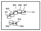
図9は、本発明の第三の実施例に係わる挟領域形成の説明図である。この例では、不要物911、912は電線のような直線状のものだけではなく、一般に自由な形状を想定している。この不要物領域911、912は実施例1、実施例2と同様に黒値(0,0,0)に置き換えられている。例えば左から順に不要物領域を含む挟領域を形成していく時、最上部の左端から、順次下方向へ、黒値の画素を探索し、黒値の画素が存在した場所で、挟領域を形成する。FIG. 9 is an explanatory diagram of the formation of the sandwiching area according to the third embodiment of the present invention. In this example, the
挟領域は、例えば黒値の画素を正方形の左端の辺の中央に合せ、右側に形成することで、実現できる。挟領域901はこのようにして、形成した第一の領域である。挟領域901を形成した時に、この挟領域901に含まれる不要物の黒値は非黒値に置き換えられる。この置き換えは、挟領域形成直後に行なっても良いが、また,挟領域に対する修復領域を探索し、置き換えることによって、非黒値にすることもできる。挟領域901の処理が終了後、次の不要物領域を含む挟領域の探索は同じく左から右へそして、各位置で、上から下に探索し、黒値の画素を探せば良い。図9の例では、不要物領域912を含む挟領域902が形成される。以下挟領域903、904、905、906、907の順で形成されていく。不要物の曲がり方が大きいときは、決定した正方形の挟領域の右側の辺ではなく、上部や下部の辺に出て行く形の領域の配置になる場合もある。その場合は、不要物は挟領域に含まれる途中までの部分しか除去されないが、以後の挟領域の探索で残った部分から新たな挟領域が形成されるため、除去処理が連続して進行していく。The sandwiched area can be realized, for example, by aligning the black value pixel with the center of the left edge of the square and forming it on the right side. The
本発明は、画像の修正、劣化画像の修復に広く使用することが出来、写真業界、広告業界、映画など画像を取り扱うあらゆる産業分野で、利用することが出来る。また、ディジタルカメラなどで撮影した画像の後処理として、画像の修復を行なうことが出来る。また、電線など不要物が存在して、取り除いて撮影できない場合は、その不要物を含めて撮影すれば、撮影後に修正を行なうことが出来る。The present invention can be widely used for correcting images and repairing deteriorated images, and can be used in all industrial fields that handle images such as the photographic industry, the advertising industry, and movies. Further, image restoration can be performed as post-processing of an image taken with a digital camera or the like. In addition, when unnecessary objects such as electric wires are present and cannot be taken for shooting, correction can be performed after shooting by shooting including the unnecessary objects.
201 入力画像
202 参照画像
203 不要物領域生成処理
204 挟領域生成処理
205 探索領域生成処理
206 探索終了のループと判定処理
207 探索処理
208 最小の誤差の領域を決定する処理
209 入力画像置き換え処理
301 不要物領域生成ブロック
302 不要物領域の黒値化処理
303 非不要領域の黒値の非黒値化処理
401 挟領域の生成ブロック
402 自由小領域の分割処理
403 挟領域生成処理
404 挟領域生成規則発生器
601−603 各種自由挟領域の生成
701−703 傾斜した扶養物領域に対応した挟領域
901−911 曲がった線状の不要物領域に対応した挟領域201
Claims (3)
Priority Applications (1)
| Application Number | Priority Date | Filing Date | Title |
|---|---|---|---|
| JP2004130439A JP2005293521A (en) | 2004-03-31 | 2004-03-31 | Method and device for removing unnecessary part of image |
Applications Claiming Priority (1)
| Application Number | Priority Date | Filing Date | Title |
|---|---|---|---|
| JP2004130439A JP2005293521A (en) | 2004-03-31 | 2004-03-31 | Method and device for removing unnecessary part of image |
Publications (1)
| Publication Number | Publication Date |
|---|---|
| JP2005293521A true JP2005293521A (en) | 2005-10-20 |
Family
ID=35326343
Family Applications (1)
| Application Number | Title | Priority Date | Filing Date |
|---|---|---|---|
| JP2004130439A Pending JP2005293521A (en) | 2004-03-31 | 2004-03-31 | Method and device for removing unnecessary part of image |
Country Status (1)
| Country | Link |
|---|---|
| JP (1) | JP2005293521A (en) |
Cited By (4)
| Publication number | Priority date | Publication date | Assignee | Title |
|---|---|---|---|---|
| WO2011089996A1 (en) * | 2010-01-20 | 2011-07-28 | 三洋電機株式会社 | Image processing device and electronic apparatus |
| JP2011170838A (en) * | 2010-01-20 | 2011-09-01 | Sanyo Electric Co Ltd | Image processing device and electronic apparatus |
| JP2020525940A (en) * | 2017-06-27 | 2020-08-27 | エヌイーシー ラボラトリーズ アメリカ インクNEC Laboratories America, Inc. | Reconstructor and controller for anomaly detection |
| KR20230001916A (en) * | 2021-06-29 | 2023-01-05 | 롯데정보통신 주식회사 | Freight classification method and device |
-
2004
- 2004-03-31 JP JP2004130439A patent/JP2005293521A/en active Pending
Cited By (6)
| Publication number | Priority date | Publication date | Assignee | Title |
|---|---|---|---|---|
| WO2011089996A1 (en) * | 2010-01-20 | 2011-07-28 | 三洋電機株式会社 | Image processing device and electronic apparatus |
| JP2011170838A (en) * | 2010-01-20 | 2011-09-01 | Sanyo Electric Co Ltd | Image processing device and electronic apparatus |
| CN102812490A (en) * | 2010-01-20 | 2012-12-05 | 三洋电机株式会社 | Image processing device and electronic equipment |
| JP2020525940A (en) * | 2017-06-27 | 2020-08-27 | エヌイーシー ラボラトリーズ アメリカ インクNEC Laboratories America, Inc. | Reconstructor and controller for anomaly detection |
| KR20230001916A (en) * | 2021-06-29 | 2023-01-05 | 롯데정보통신 주식회사 | Freight classification method and device |
| KR102547408B1 (en) | 2021-06-29 | 2023-06-22 | 롯데정보통신 주식회사 | Freight classification method and device |
Similar Documents
| Publication | Publication Date | Title |
|---|---|---|
| US8194974B1 (en) | Merge and removal in a planar map of an image | |
| EP1459259B1 (en) | Generating replacement data values for an image region | |
| JP4908440B2 (en) | Image processing apparatus and method | |
| JP5597096B2 (en) | Image processing apparatus, image processing method, and program | |
| US20150332435A1 (en) | Image processing apparatus, image processing method, and computer-readable recording medium | |
| JP4413971B2 (en) | Image interpolation apparatus, image interpolation method, and image interpolation program | |
| US7929755B1 (en) | Planar map to process a raster image | |
| JP2005528643A (en) | Video scaling | |
| WO2017096814A1 (en) | Image processing method and apparatus | |
| Patel et al. | Accelerated seam carving for image retargeting | |
| CN106251322A (en) | Image processing equipment, image processing method and image processing system | |
| Najgebauer et al. | Inertia‐based Fast Vectorization of Line Drawings | |
| Lieng et al. | Shading Curves: Vector‐Based Drawing With Explicit Gradient Control | |
| US9412188B2 (en) | Method and image processing system for removing a visual object from an image | |
| JP2005293521A (en) | Method and device for removing unnecessary part of image | |
| US9779528B2 (en) | Text realization | |
| JP7405370B2 (en) | Depth map super resolution device, depth map super resolution method, and depth map super resolution program | |
| JP6196517B2 (en) | Target image generation support apparatus, target image generation support method, and program | |
| US7734118B2 (en) | Automatic image feature embedding | |
| JP7592932B1 (en) | Iterative graph-based image enhancement with object separation | |
| US20140347399A1 (en) | Image scaling for images including low resolution text | |
| CN112927288B (en) | Image coordinate extraction method, image processing device and storage device | |
| JP6159211B2 (en) | Target image generation support apparatus, target image generation support method, and program | |
| Eng et al. | Numerical evaluation for solving Poisson image blending problem by four-point Egsor iterative method | |
| JP2009164897A (en) | Binarizing device and binarization processing program |