JP2005293510A - Disaster prevention system - Google Patents
Disaster prevention system Download PDFInfo
- Publication number
- JP2005293510A JP2005293510A JP2004111535A JP2004111535A JP2005293510A JP 2005293510 A JP2005293510 A JP 2005293510A JP 2004111535 A JP2004111535 A JP 2004111535A JP 2004111535 A JP2004111535 A JP 2004111535A JP 2005293510 A JP2005293510 A JP 2005293510A
- Authority
- JP
- Japan
- Prior art keywords
- control
- line
- voltage
- power
- smoke prevention
- Prior art date
- Legal status (The legal status is an assumption and is not a legal conclusion. Google has not performed a legal analysis and makes no representation as to the accuracy of the status listed.)
- Pending
Links
- 230000002265 prevention Effects 0.000 title claims abstract description 97
- 239000000779 smoke Substances 0.000 claims abstract description 79
- 238000001514 detection method Methods 0.000 claims abstract description 56
- 230000005856 abnormality Effects 0.000 claims abstract description 13
- 238000012544 monitoring process Methods 0.000 claims description 37
- 230000004913 activation Effects 0.000 claims description 17
- 230000003213 activating effect Effects 0.000 claims description 3
- 238000007599 discharging Methods 0.000 abstract 5
- 239000000203 mixture Substances 0.000 abstract 1
- 230000000630 rising effect Effects 0.000 description 10
- 238000003708 edge detection Methods 0.000 description 7
- 238000010586 diagram Methods 0.000 description 3
- 239000003990 capacitor Substances 0.000 description 1
- 238000012790 confirmation Methods 0.000 description 1
- 230000007274 generation of a signal involved in cell-cell signaling Effects 0.000 description 1
- 239000004065 semiconductor Substances 0.000 description 1
Images
Landscapes
- Fire Alarms (AREA)
Abstract
Description
この発明は、線路を介して火災受信機と防排煙端末との間を接続し、防排煙端末の制御と作動監視を行う防災システムに関する。 The present invention relates to a disaster prevention system in which a fire receiver and a smoke prevention terminal are connected via a track to control and monitor the operation of the smoke prevention terminal.
火災受信機と防火戸や排煙機などの防排煙端末とを3本又は2本の配線で接続し、防排煙端末の制御および作動確認を行う制御装置がある。 There is a control device that controls a fire prevention terminal and confirms its operation by connecting a fire receiver and a smoke prevention terminal such as a fire door or smoke exhauster with three or two wires.
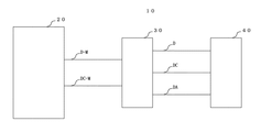
従来の防災システムとして特許文献1に開示されているシステム構成を図3に示す。防災システム10は火災受信機20と、火災受信機20と第1の制御線D−M、第1の共通線DC−Mの2線を介して接続されたアダプタ30、アダプタ30と第2の制御線D、第2の共通線DC、応答線DAで接続された防排煙端末40から構成される。ここで図示しない火災感知器などから火災信号を受信すると、火災受信機20は設定に基づいて防排煙端末40を起動する起動信号を制御線D−Mを介して出力する。防排煙端末40は起動信号により作動するとともに、応答線DAを介してアダプタ30及び火災受信機20に応答信号を出力する。応答信号を受信した火災受信機20は、図示しない応答回路により防排煙端末30が作動したことを確認する。
上記従来技術によれば、防排煙機端末の起動制御と作動監視を確実に行うことができたが、2線のみを使用して制御線の断線短絡信号と作動応答信号を確認するため、すなわち一対の制御線により防排煙端末への電力供給も行うので、定期的に制御出力を瞬断させて断線短絡の監視を行う必要があった。 According to the above prior art, it was possible to reliably perform start control and operation monitoring of the smoke evacuation terminal, but in order to confirm the disconnection short circuit signal and the operation response signal of the control line using only two wires, That is, since the power supply to the smoke-proof terminal is also performed by a pair of control lines, it is necessary to periodically disconnect the control output and monitor the disconnection short circuit.
しかし、上記従来技術を使用すると、例えば瞬断を起動信号と判断してしまう(制御信号の瞬断を許容しない)防排煙端末の接続が困難となる問題があった。 However, when the above-described conventional technology is used, there is a problem that it becomes difficult to connect a smoke prevention terminal that, for example, determines a momentary interruption as an activation signal (does not allow a momentary interruption of a control signal).
また制御線と電源線を同一にすると、火災受信機から制御信号と制御電流も防排煙端末に流しているため、配線を長くすると電圧降下が大きくなる。このため消費電力の大きい防排煙端末を前記システムに接続する場合には配線距離を制限しなければならい問題や、電圧によりアダプターを制御しているので大きい電圧降下が起こるとアダプターが正常動作できなくなるという問題もあった。 If the control line and the power line are the same, a control signal and a control current are also sent from the fire receiver to the smoke-proofing terminal. Therefore, if the wiring is lengthened, the voltage drop increases. For this reason, when connecting smoke-proof terminals with high power consumption to the above system, the adapter must be able to operate normally if there is a problem that the wiring distance must be limited, or the voltage is controlled because the adapter is controlled by voltage. There was also a problem of disappearing.
従って本発明は、上記課題を克服し、簡単な構成で火災受信機と防排煙端末とを接続する線路の状態および防排煙端末の作動状態がわかる防災システムを提供することを目的とする。 Accordingly, an object of the present invention is to overcome the above-described problems and provide a disaster prevention system in which the state of the line connecting the fire receiver and the smoke prevention terminal with a simple configuration and the operation state of the smoke prevention terminal can be understood. .
上記課題を解決するため、本発明の請求項1に記載の発明は、一対の制御線に接続されたアダプタと、一対以上の線路を介してアダプタと接続された防排煙端末とを有する防災システムにおいて、
アダプタは、
前記防排煙端末を起動または復帰させる電力を前記制御線と電気的に分離されて供給する一対の電源線に接続され、
前記制御線に印可された所定の電圧を監視し、
前記所定の電圧が所定の監視電圧よりも高くなると防排煙端末を起動させ、前記所定の監視電圧より高い状態が所定時間以上検出されなくなると防排煙端末を復帰させる制御信号検出手段を備え、
防排煙端末を起動または復帰させる電力を前記電源線から供給し、前記複数対の線路を介して防排煙端末に出力する
構成とした。
In order to solve the above-mentioned problems, the invention according to
Adapter is
Connected to a pair of power supply lines for supplying power for starting or returning the smoke-proof terminal to be electrically separated from the control line;
Monitoring a predetermined voltage applied to the control line;
Control signal detection means for starting the smoke prevention terminal when the predetermined voltage becomes higher than the predetermined monitoring voltage and returning the smoke prevention terminal when a state higher than the predetermined monitoring voltage is not detected for a predetermined time or more. ,
Electric power for starting or returning the smoke prevention terminal is supplied from the power line, and output to the smoke prevention terminal via the plurality of pairs of lines.
この請求項1に記載の発明によれば、防排煙端末を制御する防災システムにおいて、防排煙端末への電源供給を制御線と電気的に分離して行うので、防排煙端末へ瞬断されることなく電源供給ができる。また、配線間距離を伸ばすことが可能になる。 According to the first aspect of the present invention, in the disaster prevention system for controlling the smoke prevention terminal, the power supply to the smoke prevention terminal is electrically separated from the control line. Power can be supplied without interruption. In addition, the distance between wirings can be increased.
また、請求項2記載の発明は、請求項1に記載された防災システムにおいて、アダプタは、
前記制御信号検出手段で前記所定の監視電圧よりも高い所定の電圧を検出すると防排煙端末を起動させる起動制御信号を出力し、
前記起動制御信号出力後に、前記所定の監視電圧より低い所定の電圧を所定時間以内検出したときに前記起動制御信号の出力を継続し、
前記所定の監視電圧より低い所定の電圧を所定時間以上検出したときに防排煙端末を復帰させる復帰制御信号を出力し、
前記起動制御信号を入力すると前記電源線から電力を供給し、前記線路を介して防排煙端末を起動させる電力を出力する起動制御出力回路と、
前記復帰制御信号を入力すると前記電源線から電力を供給し、前記線路を介して防排煙端末を復帰させる電力を出力する復帰制御出力回路と
をさらに備えた構成とした。
The invention according to
When the control signal detecting means detects a predetermined voltage higher than the predetermined monitoring voltage, it outputs an activation control signal for activating the smoke prevention terminal,
After outputting the activation control signal, when the predetermined voltage lower than the predetermined monitoring voltage is detected within a predetermined time, the output of the activation control signal is continued.
When a predetermined voltage lower than the predetermined monitoring voltage is detected for a predetermined time or more, a return control signal for returning the smoke prevention terminal is output,
When the start control signal is input, power is supplied from the power line, and a start control output circuit that outputs power for starting the smoke prevention terminal via the line, and
When the return control signal is input, power is supplied from the power line, and a return control output circuit that outputs power for returning the smoke prevention terminal via the line is further provided.
この請求項2に記載の発明によれば、アダプタの制御信号検出手段で検出される制御線からの電圧について、瞬断信号と防排煙端末復帰制御信号の識別を可能とした。 According to the second aspect of the present invention, the instantaneous interruption signal and the smoke-proof terminal return control signal can be identified for the voltage from the control line detected by the control signal detection means of the adapter.
また、請求項3記載の発明は、請求項1乃至請求項2に記載された防災システムのアダプタに、
前記電源線の異常を検出すると前記制御線に前記所定の電圧よりも高い所定の異常検出電圧を出力する電源線異常検出手段
を備えた構成とした。
Moreover, invention of
When an abnormality is detected in the power supply line, power supply line abnormality detection means for outputting a predetermined abnormality detection voltage higher than the predetermined voltage to the control line is provided.
この請求項3の発明によれば、一対の制御線と電気的に分離された一対の電源線の異常を検出することを可能とした。 According to the third aspect of the present invention, it is possible to detect an abnormality in a pair of power supply lines that are electrically separated from the pair of control lines.
本発明によれば、防排煙端末を制御する防災システムにおいて、簡単な構成で防排煙端末の制御線と電源線との短絡を保護できるとともに防排煙端末を作動させる電源の瞬断が無くなり防排煙端末への確実な電源供給により起動・復帰制御を行うことができる。また火災受信機と電源線間の配線間距離を伸ばすことができるとともに制御線と電源線の異常検出ができる。 According to the present invention, in the disaster prevention system for controlling the smoke prevention terminal, the short circuit between the control line of the smoke prevention terminal and the power line can be protected with a simple configuration, and the power supply for operating the smoke prevention terminal can be instantaneously interrupted. The start-up / return control can be performed by the reliable power supply to the smoke-proof terminal. In addition, the distance between the wiring between the fire receiver and the power line can be increased, and an abnormality in the control line and the power line can be detected.
以下、図を参照して本発明の実施の形態について詳細に説明する。
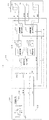
まず、防災システム10の構成を説明する。図1は防災システム10の簡単な回路構成を示す図である。
尚、図3と同様の機能及び名称を有するものについては同じ番号が記載されている。
Hereinafter, embodiments of the present invention will be described in detail with reference to the drawings.
First, the configuration of the
In addition, the same number is described about what has a function and a name similar to FIG.
防災システム10は、火災受信機20、制御線D−Mと第1の共通線DC−M(一対の制御線)、電源線P+と第2の共通線P−(一対の電源線)、制御線と電源線を介して接続されたアダプタ30、アダプタ30と起動制御線D、第2の共通線DC、応答線DA−M、第1の共通線DC−M、復帰制御線Df及び第2の共通線DCfを介して接続された防排煙端末40から構成される。なお、図1では1組のアダプタ30と防排煙端末40を示しているが、アダプタおよび防排煙端末の複数組が各組毎に一対の制御線と一対の電源線を介して火災受信機に接続されている構成でも良い。
The
火災受信機20は、ビルの防災センターや集合住宅の管理人室等に設置され、建物全体の監視を行うものである。図示しない火災感知器などから火災信号を受信すると、火災受信機20に設けられた図示されない操作パネルのスイッチ操作(手動)や自動制御を行い、連動設定等の各種設定に基づいて防排煙端末40を起動または復帰させる。
The
アダプタ30は、従来から用いられている3線式の防排煙端末や復帰機能を兼ね備えた防排煙端末40などを本発明の防災システム10に接続するために使用されるものである。
The
防排煙端末40は例えば防火戸、排煙機などであり、火災受信機20からの制御信号により所定の動作を行うとともに、応答線DAを介して作動応答信号を出力する。
The
火災受信機20には、防排煙端末40を作動させるときに閉じられる制御接点S1、制御接点S1と並列に接続された抵抗R1、電圧変化を検出する状態検出部21(状態検出手段)、アダプタ30及び防排煙端末40へ電力を供給するアイソレータ22が設けられている。
The
ここでアイソレータ22は、火災受信機20の電源を絶縁型DC−DCコンバータによって制御接点S1、抵抗R1、更には制御線D−M及び第1の共通線DC−M(一対の制御線)により構成される制御系統の各回路部(火災受信機20の制御接点S1や抵抗R1あるいはアダプタ30の制御電圧検出回路31等)と、電源線P+及び第2の共通線P−(一対の電源線)により構成される電源系統の各回路部(アダプタ30の起動制御出力回路36や防排煙端末40の復帰部42等)を電気的に分離している。
Here, the isolator 22 uses a control contact S1, a resistor R1, a control line DM, and a first common line DC-M (a pair of control lines) as a power source for the
アダプタ30には制御線D−Mと第1の共通線DC−M間の電圧(制御信号)を検出する制御電圧検出回路31、立上り検出回路32、立下り検出回路33、タイマ1(34)、タイマ2(35)、起動制御出力回路36、復帰制御出力回路37、応答線DA−Mと直列に接続された抵抗R2、制御線D−Mと第1の共通線DC−Mの間に接続された抵抗R3、抵抗R3と直列に接続された電源監視接点S3を備えた電源監視部(電源監視リレー)が設けられている。
The
防排煙端末40にはアダプタ30の起動制御部36から所定の作動電圧が印加され、一対の電源線から電力を供給して作動する駆動部41、駆動部41の作動により起動制御線D側の接点bから応答線DA−M側の接点aに切り換わる作動応答接点S2、復帰制御部37からの所定の作動電圧が印可され所定の作動電圧が印加され、一対の電源線から電力を供給して作動する復帰部42が設けられている。起動部41や復帰部42としては、例えばソレノイドなどが用いられる。
A predetermined operation voltage is applied to the
監視時と防排煙端末の制御時の動作についてそれぞれ説明する。
なお説明の都合上、防排煙端末40を作動させる所定の作動電圧(一対の電源線の電圧)をEv(V)とし、火災受信機20からアダプタ30へ出力される防排煙端末30の制御信号(制御電圧)をEs(V)とし、抵抗R1、抵抗R2、抵抗R3はそれぞれ同じ抵抗値とする。また後述するアダプタ30の制御電圧検出回路31は2/3Es(V)(所定の監視電圧)以上の電圧を検出したときにHighの信号(起動制御信号)を出力し、2/3Es(V)以下の電圧を検出するときはLowの信号(復帰制御信号)を出力するものとする(所定の監視電圧)。必ずしもこの電圧値2/3Es(V)に限られず、所定の監視電圧が検出できればよい。また後述する制御電圧検出回路31は、十分大きな入力抵抗を持ち、回路の動作に影響しないものとする。
The operation at the time of monitoring and at the time of controlling the smoke prevention terminal will be described.
For convenience of explanation, a predetermined operating voltage (a voltage of a pair of power supply lines) for operating the
監視時には火災受信機20の制御接点S1は開いた状態であり、アダプタ30の電源監視接点S3は閉じた状態である。状態検出部21(状態検出手段)で検出される正常監視時のA点の電圧(所定の電圧)は、抵抗R1と抵抗R3との合成抵抗でEsを分圧した電圧となるので、1/2Es(V)となる。
At the time of monitoring, the control contact S1 of the
もしここで制御線D−Mと第1の共通線DC−M(一対の制御線)に短絡が発生した場合にはA点の電圧が0(V)となる。また制御線D−Mと第1の共通線DC−M(一対の制御線)に断線が発生した場合にはA点の電圧はEs(V)となる。 If a short circuit occurs between the control line DM and the first common line DC-M (a pair of control lines), the voltage at the point A becomes 0 (V). Further, when a disconnection occurs in the control line DM and the first common line DC-M (a pair of control lines), the voltage at the point A becomes Es (V).
また、電源線P+と第2の共通線P−(一対の電源線)が断線した場合には、電源監視部の電源監視リレーのコイルに電源が供給されなくなり電源監視部の電源監視接点S3を開く。電源監視接点S3が開放されると、抵抗R3と第1の共通線DC−Mとの接続が断たれるので、制御線D−Mと第1の共通線(一対の制御線)が断線した状態と同じになり、A点の電圧はEs(V)となる。 When the power supply line P + and the second common line P- (a pair of power supply lines) are disconnected, power is not supplied to the coil of the power supply monitoring relay of the power supply monitoring unit, and the power supply monitoring contact S3 of the power supply monitoring unit is connected. open. When the power supply monitoring contact S3 is opened, the connection between the resistor R3 and the first common line DC-M is disconnected, so that the control line DM and the first common line (a pair of control lines) are disconnected. It becomes the same as the state, and the voltage at the point A becomes Es (V).
電源線P+と第2の共通線P−(一対の電源線)に短絡が発生した場合には電源監視部の電源監視リレーのコイルに電源が供給されなくなる。すなわち一対の電源線が断線した場合や一対の制御線が断線した場合と同じ状態になり、A点の電圧はEs(V)となる。
すなわち、電源監視部が本発明の電源線異常検出手段である。
When a short circuit occurs between the power supply line P + and the second common line P- (a pair of power supply lines), power is not supplied to the coil of the power supply monitoring relay of the power supply monitoring unit. That is, when the pair of power supply lines is disconnected or when the pair of control lines is disconnected, the voltage at the point A is Es (V).
That is, the power supply monitoring unit is the power line abnormality detection means of the present invention.
このように状態検出手段がA点の電圧を監視することにより、一対の制御線の正常、短絡、断線の状態や一対の電源線の正常、短絡又は断線の状態を検出することができる。状態検出部21としては電圧変化を検出できるもの、例えばコンパレーターやA/Dコンバータなどが使用される。なお、一対の制御線のいずれか一方と一対の電源線のいずれか一方との短絡は制御系と電源系を電気的に分離しているので発生しない。
As described above, the state detection means monitors the voltage at the point A, so that it is possible to detect the normal state, the short circuit state, and the disconnection state of the pair of control lines and the normal state, the short circuit state, or the disconnection state of the pair of power supply lines. As the
ついで防排煙端末の制御時の動作を説明する。
ここでアダプタ30の制御電圧検出回路31、立上り検出回路32、立下り検出回路33、タイマ1(34)及びタイマ2(35)は、一つのCPUで構成されており、火災受信機20からの制御電圧Es(V)をもとにCPU内で処理されるものとする。なお、アダプタ30の各回路部を抵抗、トランジスタ、リレー、フォトカプラ、コンデンサ等の半導体素子でアナログ回路構成することも容易に実現可能である。
Next, the operation at the time of controlling the smoke prevention terminal will be described.
Here, the control
またアダプタ30の制御電圧検出回路31は2/3Es(V)以上の電圧を検出したときに立上り検出回路32、立下り検出回路33へHighの信号(起動制御信号)を出力するので、2/3Es(V)以下の電圧を検出するときは立上り検出回路32、立下り検出回路33へLowの信号(復帰制御信号)を出力するものとする。
Further, the control
火災受信機20は防排煙端末40を作動させるために制御接点S1を閉じる。このときアダプタ30への入力電圧はEs(V)となる。また火災受信機20は、防排煙端末40の作動を確認するため、定期的(例えば数秒おき)に制御接点S1を開く制御も行っている。このときアダプタ30への入力電圧は正常監視時のA点の電圧(所定の電圧)と同じになり、すなわち、抵抗R1と抵抗R3との合成でEsを分圧した電圧1/2Es(V)となる。
The
従って制御接点S1が閉じられたときに制御電圧検出回路31は立上り検出回路32、立下り検出回路33へHighの信号(起動制御信号)を出力し、制御接点S1が定期的に開かれたときに瞬断信号として立上り検出回路32、立下り検出回路33へLowの信号(復帰制御信号)を出力する。
Therefore, when the control contact S1 is closed, the control
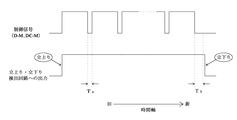
図2は一対の制御線を介してアダプタ30へ入力される制御信号(所定の電圧)とその制御信号に基づいて制御電圧監視手段31が後段の立上り検出回路32及び立下り検出回路33への出力する制御電圧(起動制御信号、駆動制御信号)を示した図である。
FIG. 2 shows a control signal (predetermined voltage) input to the
例えば、火災受信機20に設けられた図示されない防排煙制御用の操作パネルの防排煙作動スイッチを押すと制御接点S1が閉じてA点の電圧はEs(V)となるが、火災受信機20の制御により、定期的に制御接点S1が開放されて瞬断されるので、瞬断時はA点の電圧は1/2Es(V)になる。従って火災受信機20からは、図2のような定期的に時間Taの間1/2Es(V)となる電圧Es(V)の起動制御信号が制御電圧検出回路31に送出される。
For example, if the smoke prevention operation switch on the operation panel for smoke prevention control (not shown) provided in the
制御電圧検出回路31は、作動スイッチ押圧後、制御電圧Es(V)を検出すると、監視電圧2/3Es(V)以上であるので、立上り検出回路32および立下り検出回路33へHighの信号を出力する。しかしその後瞬断信号の1/2Es(V)の信号を時間Taの間検出するが、予め設定された時間Tb以上検出しない場合には、立上り検出回路32および立下り検出回路33へHighの信号を継続して出力する。
When the control
立上り検出回路32では、制御電圧検出回路31から出力されるHighの信号(起動制御信号)の立上りを検出すると、その時点からタイマ1(34)で計時を開始し、予め設定された時間(例えばt1秒間)だけ防排煙端末を起動制御する信号(起動制御信号)を起動制御出力回路36へ出力する。
In the rising edge detection circuit 32, when the rising edge of the High signal (startup control signal) output from the control
続いて起動制御出力回路36は、制御線と電気的に分離された一対の電源線より防排煙端末40の駆動部41へ電力をt1秒間供給して防排煙端末40を起動させる。ここで起動制御出力回路36内の一対の電源線への電力供給の制御はリレーやフォトカプラ等を使用すれば良く、制御系統と電源系統の電気的接続が発生しないものであれば良い。
Subsequently, the activation
次に防排煙端末40の作動応答確認について説明する。
防排煙端末40が起動して作動が完了すると、作動応答接点S2が起動制御線D側のbの位置から応答線DA−M側のaの位置に切り替わり、抵抗R2が応答線DA−Mと第1の共通線DC−Mを介して抵抗R3と並列接続される。すなわち抵抗R2は応答信号発生手段である。なお、作動応答接点S2は、制御系統と電源系統が電気的に分離された状態で接点の切り替えを行うものとする。
Next, the operation response confirmation of the
When the
制御接点S1を開くことによりアダプタ30への入力電圧が2/3Es(V)以下となり、このときのA点の電圧は抵抗R1の抵抗値と、抵抗R2と抵抗R3の合成でEs(V)を分圧した電圧となるので、1/3Es(V)となる。
By opening the control contact S1, the input voltage to the
すなわちA点の電圧が1/3Es(V)になったことを状態検出部21が検出すると、火災受信機20が防排煙端末40の作動を確認したこととなる。
That is, when the
なお作動確認時に状態検出部21で所定の端末作動応答電圧が検出されない場合(A点の電圧が1/3Es(V)以外)には何らかの異常が発生していることが分かる。もし防排煙端末40が作動していない場合、A点で検出される電圧は抵抗R1と抵抗R3でEs(V)を分圧した電圧となるので、1/2Es(V)となる。作動スイッチ押圧後、時間Taを経過してもこの端末作動応答電圧1/3Es(V)を状態検出部21で検出しなければ、防排煙端末40が不作動だったことが分かる。なお、この状態検出部21で作動スイッチ押圧後に時間Ta以上経過しても端末応答作動電圧を検出したか否かの判断は、火災受信機20で判断することができる。
In addition, when a predetermined terminal operation response voltage is not detected by the
このように火災受信機20が状態検出手段がA点の電圧を監視することにより、防排煙端末30の作動状態を確認することができる。
As described above, the
防排煙を復帰させる場合は、火災受信機20の図示されない防排煙制御用の操作パネルの防排煙を作動させる為の作動スイッチを解除すると火災受信機20から制御接点S1が開かれた状態になる。すなわち図2のような制御信号、すなわち予め定められた時間Tb以上の間、1/2Es(V)となる信号が制御電圧検出回路31に送出される(時間Tb以上の間、Es(V)である信号が制御電圧検出回路31に送出されなくなる)。
When returning smoke prevention, the control contact S1 is opened from the
制御電圧検出回路31は、時間Tbの間、電圧1/2Es(V)の検出を継続すると、立上り検出回路32および立下り検出回路33へLowの信号(復帰制御信号)を出力する。
The control
立下り検出回路33では、制御電圧検出回路31から出力されるHighの信号(起動制御信号)からLowの信号(復帰制御信号)の切り替わり、すなわち立下りを検出すると、その時点からタイマ2(35)で計時を開始し、予め設定された時間(例えばt2秒間)だけ防排煙端末を復帰制御する信号(復帰制御信号)を復帰制御出力回路37へ出力する。
In the fall detection circuit 33, when a high signal (startup control signal) output from the control
続いて復帰制御出力回路37は、制御線と電気的に分離された一対の電源線より防排煙端末40の復帰部42へ電力をt2秒間供給して防排煙端末40を復帰させる。ここで復帰制御出力回路37内の一対の電源線への電力供給の制御はリレーやフォトカプラ等を使用すれば良く、制御系統と電源系統の電気的接続が発生しないものであれば良い。
Subsequently, the return control output circuit 37 supplies power to the
このように本発明は、応答信号線を省略して制御信号の送出を行うとともに防排煙端末の作動を監視する防災システムにおいて、一対の制御線からの電力供給を行わずに新たに一対の電力線を設け、電源監視部を設けることによりこれら2組の接続線を電気的に分離して互いの短絡を回避するとともに電源線および制御線の異常を検出できるようなる。 As described above, the present invention provides a new pair of control signals without sending the power from the pair of control lines in the disaster prevention system that transmits the control signal while omitting the response signal line and monitors the operation of the smoke prevention terminal. By providing a power line and a power supply monitoring unit, it is possible to electrically separate these two sets of connection lines to avoid mutual short circuit and to detect abnormality of the power supply line and the control line.
なお、本発明において本発明を逸脱しない範囲で適宜変更可能である。
例えば、アダプタ30を防排煙端末40と別体とせず、駆動信号検出手段と応答信号発生手段を防排煙端末40内に組み込み、火災受信機20と防排煙端末40を互いに電気的に分離された制御線及び電源線を介して接続するようにしてもよい。
Note that the present invention can be modified as appropriate without departing from the scope of the present invention.
For example, the
また本実施例において防排煙端末への制御操作(起動・復帰)は、火災受信機側20の図示されない操作パネルの起動スイッチ操作(押圧・解除)により行ったが、起動スイッチと復帰スイッチを別に設けても良い。
In this embodiment, the control operation (start / return) to the smoke prevention terminal is performed by the start switch operation (press / release) of the operation panel (not shown) on the
また本実施例においては防排煙端末制御信号を制御線へ出力し、アダプタからの出力信号を検出して判断する状態検出部を備えた火災受信機について説明したが、これに限定されず、防災システムの上記制御機能を備えるものであれば良い(防災盤、連動制御盤等)。 In the present embodiment, the smoke receiver terminal control signal is output to the control line, and the fire receiver including the state detection unit that detects and determines the output signal from the adapter has been described. What is necessary is just to be provided with the said control function of a disaster prevention system (a disaster prevention panel, an interlocking control panel, etc.).
また制御系統(制御線D−M及び第1の共通線DC−M)と電源系統(電源線P+、第2の共通線P−)を電気的に分離する手段として絶縁型DC−DCコンバータを使用したが、電気的に分離できれば他のアイソレータを使用したり、あるいは他の手段を使用したりしても良い。なお、本実施例では、全ての配線を一対にして記載したが、本発明のように電源線の共通線、起動制御線の共通線および復帰制御線の共通線が電気的に接続(同電位)されているときは一つの共通線でアダプタと防排煙端末を接続しても良い。 Also, an insulating DC-DC converter is used as means for electrically separating the control system (control line DM and first common line DC-M) and the power supply system (power supply line P +, second common line P-). Although used, other isolators or other means may be used as long as they can be electrically separated. In this embodiment, all the wirings are described as a pair. However, as in the present invention, the common line of the power supply line, the common line of the start control line, and the common line of the return control line are electrically connected (the same potential). ), The adapter and smoke-proof terminal may be connected with a single common line.
例えば火災受信機の電源とは別の電源を各アダプタの近傍に設置して一対の制御線と電気的に分離して、電源線P+及び第2の共通線P−を介して防排煙端末へ作動用の電力を供給するようにしても本発明は実施可能である。またはアダプタと防排煙端末の各組をグループに分けて各アダプタ間を渡り配線で接続してグループ毎の近傍に別電源を各々設置して電源線P+及び第2の共通線P−を介して防排煙端末へ作動用の電力を供給するようにしても良い。これらの場合には火災受信機と防排煙端末間の配線間距離を大幅に延長することが容易に実現できる。 For example, a power source different from the power source of the fire receiver is installed in the vicinity of each adapter and electrically separated from the pair of control lines, and the smoke-proof terminal via the power line P + and the second common line P- The present invention can be implemented even if power for operation is supplied. Alternatively, each pair of adapter and smoke-proof terminal is divided into groups and connected between each adapter by connecting wires, and a separate power source is installed in the vicinity of each group, via the power line P + and the second common line P- Then, the operation power may be supplied to the smoke prevention terminal. In these cases, it is possible to easily extend the distance between the wires between the fire receiver and the smoke prevention terminal.
10 防災システム
20 火災受信機
21 状態検出部(状態検出手段)
22 アイソレータ(絶縁型DC/DCコンバータ)
30 アダプタ
31 制御電圧検出回路(制御信号検出手段)
32、33 立上り・立下り検出回路
34、35 タイマ
36、37 起動・復帰制御出力回路
40 防排煙端末
41 駆動部
42 復帰部
S1 制御接点
S2 作動応答接点
S3 電源監視接点
D−M 制御線
DC−M 第1の共通線
D 起動制御線
DC 第2の共通線
Df 復帰制御線
DCf 第2の共通線
P+ 電源線
P− 第2の共通線
DA−M 応答線
10
22 Isolator (Insulated DC / DC Converter)
30
32, 33 Rising / falling
Claims (3)
前記アダプタは、
前記防排煙端末を起動または復帰させる電力を前記制御線と電気的に分離されて供給する一対の電源線に接続され、
前記制御線に印可された所定の電圧を監視し、
前記所定の電圧が所定の監視電圧よりも高くなると防排煙端末を起動させ、前記所定の監視電圧より高い状態が所定時間以上検出されなくなると防排煙端末を復帰させる制御信号検出手段を備え、
防排煙端末を起動または復帰させる電力を前記電源線から供給し、前記複数対の線路を介して防排煙端末に出力する
ことを特徴とする防災システム。 In a disaster prevention system having an adapter connected to a pair of control lines and a smoke prevention terminal connected to the adapter via a pair of lines or more,
The adapter is
Connected to a pair of power lines for supplying power for starting or returning the smoke-proof terminal to be electrically separated from the control line;
Monitoring a predetermined voltage applied to the control line;
Control signal detecting means for starting the smoke prevention terminal when the predetermined voltage becomes higher than the predetermined monitoring voltage and returning the smoke prevention terminal when a state higher than the predetermined monitoring voltage is not detected for a predetermined time or more. ,
A disaster prevention system, wherein power for starting or returning a smoke prevention terminal is supplied from the power supply line and output to the smoke prevention terminal via the plurality of pairs of lines.
前記制御信号検出手段で前記所定の監視電圧よりも高い所定の電圧を検出すると防排煙端末を起動させる起動制御信号を出力し、
前記起動制御信号出力後に、前記所定の監視電圧より低い所定の電圧を所定時間以内検出したときに前記起動制御信号の出力を継続し、
前記所定の監視電圧より低い所定の電圧を所定時間以上検出したときに防排煙端末を復帰させる復帰制御信号を出力し、
前記起動制御信号を入力すると前記電源線から電力を供給し、前記線路を介して防排煙端末を起動させる電力を出力する起動制御出力回路と、
前記復帰制御信号を入力すると前記電源線から電力を供給し、前記線路を介して防排煙端末を復帰させる電力を出力する復帰制御出力回路と
をさらに備えたことを特徴とする請求項1に記載の防災システム。 The adapter is
When the control signal detecting means detects a predetermined voltage higher than the predetermined monitoring voltage, it outputs an activation control signal for activating the smoke prevention terminal,
After outputting the activation control signal, when the predetermined voltage lower than the predetermined monitoring voltage is detected within a predetermined time, the output of the activation control signal is continued.
When a predetermined voltage lower than the predetermined monitoring voltage is detected for a predetermined time or more, a return control signal for returning the smoke prevention terminal is output,
When the start control signal is input, power is supplied from the power line, and a start control output circuit that outputs power for starting the smoke prevention terminal via the line, and
The power supply line further supplies power from the power supply line when the return control signal is input, and further includes a return control output circuit that outputs power for returning the smoke prevention terminal via the line. The described disaster prevention system.
Priority Applications (1)
| Application Number | Priority Date | Filing Date | Title |
|---|---|---|---|
| JP2004111535A JP2005293510A (en) | 2004-04-05 | 2004-04-05 | Disaster prevention system |
Applications Claiming Priority (1)
| Application Number | Priority Date | Filing Date | Title |
|---|---|---|---|
| JP2004111535A JP2005293510A (en) | 2004-04-05 | 2004-04-05 | Disaster prevention system |
Publications (1)
| Publication Number | Publication Date |
|---|---|
| JP2005293510A true JP2005293510A (en) | 2005-10-20 |
Family
ID=35326334
Family Applications (1)
| Application Number | Title | Priority Date | Filing Date |
|---|---|---|---|
| JP2004111535A Pending JP2005293510A (en) | 2004-04-05 | 2004-04-05 | Disaster prevention system |
Country Status (1)
| Country | Link |
|---|---|
| JP (1) | JP2005293510A (en) |
Cited By (1)
| Publication number | Priority date | Publication date | Assignee | Title |
|---|---|---|---|---|
| JP2018206013A (en) * | 2017-06-02 | 2018-12-27 | ニッタン株式会社 | Fireproof system, control device, and control method |
-
2004
- 2004-04-05 JP JP2004111535A patent/JP2005293510A/en active Pending
Cited By (1)
| Publication number | Priority date | Publication date | Assignee | Title |
|---|---|---|---|---|
| JP2018206013A (en) * | 2017-06-02 | 2018-12-27 | ニッタン株式会社 | Fireproof system, control device, and control method |
Similar Documents
| Publication | Publication Date | Title |
|---|---|---|
| USRE43177E1 (en) | Apparatus and method for preventing an electrical backfeed | |
| JP2009022158A6 (en) | Group protection module for switchgear device and switchgear device having such group protection module | |
| JP4762300B2 (en) | Traffic light control system | |
| JP4752775B2 (en) | Power line carrier communication system | |
| US6778371B2 (en) | Device for supplying electrical power to detectors, control devices and signaling devices | |
| JP4866283B2 (en) | Apartment house trunk line current control system with operation guarantee function | |
| JP7746356B2 (en) | booster | |
| CN110021917B (en) | Fault isolation positioning system | |
| JP5924069B2 (en) | Monitoring system | |
| JP4589750B2 (en) | Data terminal equipment for feeding hub | |
| JP2006235782A (en) | Fire alarm system for residence | |
| US11501631B2 (en) | Fire alarm system and booster | |
| JP6579769B2 (en) | Relay device and alarm system | |
| JP2775063B2 (en) | Fire monitoring method and system using multiplex transmission | |
| JP2000244373A (en) | Repeater and network using the same | |
| JP6676803B2 (en) | First device power supply device and alarm system | |
| CN113071322B (en) | Control method and device of alternating current leakage detection device and railway vehicle | |
| US20080232613A1 (en) | Method and apparatus for providing volume control with dc supervision | |
| JP2004206317A (en) | Disaster prevention system | |
| JP2001338361A (en) | Device for detecting disconnection/short circuit of smoke protection and discharge line in smoke protection and discharge interlocking system | |
| JP2000253585A (en) | Distributed power supply system | |
| JP2007174812A (en) | Power feeding device and system and terminating device | |
| JP2003006763A (en) | Repeater for fire alarm system and fire alarm system using the repeater | |
| JP5013614B2 (en) | Dwelling unit monitoring system | |
| JP2024172213A (en) | Monitoring event determination circuit and monitoring system |
Legal Events
| Date | Code | Title | Description |
|---|---|---|---|
| A621 | Written request for application examination |
Free format text: JAPANESE INTERMEDIATE CODE: A621 Effective date: 20070129 |
|
| A131 | Notification of reasons for refusal |
Free format text: JAPANESE INTERMEDIATE CODE: A131 Effective date: 20090612 |
|
| A02 | Decision of refusal |
Free format text: JAPANESE INTERMEDIATE CODE: A02 Effective date: 20091106 |