JP2005293467A - Hidden line processing method - Google Patents
Hidden line processing method Download PDFInfo
- Publication number
- JP2005293467A JP2005293467A JP2004110994A JP2004110994A JP2005293467A JP 2005293467 A JP2005293467 A JP 2005293467A JP 2004110994 A JP2004110994 A JP 2004110994A JP 2004110994 A JP2004110994 A JP 2004110994A JP 2005293467 A JP2005293467 A JP 2005293467A
- Authority
- JP
- Japan
- Prior art keywords
- hidden line
- memory
- line processing
- extracted
- upper limit
- Prior art date
- Legal status (The legal status is an assumption and is not a legal conclusion. Google has not performed a legal analysis and makes no representation as to the accuracy of the status listed.)
- Granted
Links
Images


Classifications
-
- G—PHYSICS
- G06—COMPUTING OR CALCULATING; COUNTING
- G06T—IMAGE DATA PROCESSING OR GENERATION, IN GENERAL
- G06T15/00—3D [Three Dimensional] image rendering
- G06T15/10—Geometric effects
- G06T15/40—Hidden part removal
Landscapes
- Physics & Mathematics (AREA)
- Engineering & Computer Science (AREA)
- Geometry (AREA)
- Computer Graphics (AREA)
- General Physics & Mathematics (AREA)
- Theoretical Computer Science (AREA)
- Image Generation (AREA)
Abstract
【課題】 メモリ使用状況やメモリ搭載量に応じて、陰線処理に要するメモリ消費量を柔軟に変更し、スワップ発生による処理速度の低下を防ぐ。
【解決手段】 予め、メモリの容量のうち陰線処理に利用する容量の上限値を設定して、2次元平面を複数の領域に分割したとき、投影された前記3次元モデルのうち領域に含まれる部分のポリゴンをそれぞれの領域で抽出し、抽出されたポリゴンに基づき各領域で消費されるメモリ消費量を算出し、算出された領域毎のメモリ消費量の最大値が上限値以上の場合、2次元平面を更に分割して分割後の領域に投影された3次元モデルに含まれるポリゴンの抽出を行い、抽出されたポリゴンに基づくメモリ消費量の算出を繰り返し、算出された領域毎のメモリ消費量の最大値が上限値を下回る場合、各領域において、抽出されたポリゴンに対し陰線処理を行い、領域毎の陰線処理データを作成した後、複数の領域の陰線処理データを結合する。
【選択図】 図3PROBLEM TO BE SOLVED: To flexibly change a memory consumption required for hidden line processing according to a memory usage state and a memory mounting amount, and prevent a decrease in processing speed due to occurrence of a swap.
When a two-dimensional plane is divided into a plurality of areas by setting an upper limit value of a capacity used for hidden line processing out of memory capacity in advance, it is included in the area of the projected three-dimensional model. If a polygon of a part is extracted in each area, a memory consumption consumed in each area is calculated based on the extracted polygon, and the maximum value of the memory consumption for each calculated area is greater than or equal to the upper limit value, 2 The polygon plane contained in the three-dimensional model projected onto the divided area is further divided, and the calculation of the memory consumption based on the extracted polygon is repeated. The memory consumption for each calculated area If the maximum value is lower than the upper limit value, hidden line processing is performed on the extracted polygons in each region to create hidden line processing data for each region, and then the hidden line processing data of a plurality of regions are combined.
[Selection] Figure 3
Description
本発明は、複数のポリゴンから構成される3次元モデルを2次元平面に投影する際の陰線を消去する、いわゆる陰線処理に関し、特にメモリ消費量を最適化して処理を行う陰線処理方法に関する。 The present invention relates to so-called hidden line processing that eliminates hidden lines when a three-dimensional model composed of a plurality of polygons is projected onto a two-dimensional plane, and more particularly to a hidden line processing method that performs processing while optimizing memory consumption.
コンピュータグラフィックスによる3次元形状を紙に印刷したり、ディスプレイに表示する際、3次元形状から稜線や輪郭線を抽出し、それを2次元平面に投影した画像が生成される。このとき、視点から3次元形状を見た場合、他の図形に隠れて実際には見ることのない稜線や輪郭線を消去、または線の種類を点線にするなどの処理、いわゆる陰線処理や陰面処理が行われている。 When a three-dimensional shape based on computer graphics is printed on paper or displayed on a display, an edge line or contour line is extracted from the three-dimensional shape, and an image is generated by projecting the ridge line or contour line onto the two-dimensional plane. At this time, when viewing the three-dimensional shape from the viewpoint, processing such as erasing ridgelines and contours that are hidden behind other graphics and not actually seen, or making the type of line a dotted line, so-called hidden line processing or hidden surface Processing is in progress.
陰線(面)処理としては、3次元形状がポリゴンの集合体として構成されていた場合、各ポリゴンについて奥行き値(Z値)を計算し、Z値の順にソートして描画するZソート法と画素単位でZ値のより小さな図形(手前側の図形)をフレームバッファに描画するZバッファ法が知られている。他にも、画面を複数の矩形ブロックに分割し陰面消去したブロック画像の生成を繰り返すことにより、陰面消去した画像の生成を高速に行えるようにする方法(特許文献1参照)や、Z値に応じて複数のブロックに分割しブロックでのソートを行うと共に、各ブロック内でのソートも行うことで高精度の描画処理を実現する方法(特許文献2参照)、空間領域を直方体に分割し、さらに各直方体を四面体に分割し、等関数値曲面を近似により求めることで高速に奥行順の決定や陰面消去を行う方法(特許文献3参照)や、稜線や輪郭線とポリゴンとの交差判定を数学的に解き、データを高精度で処理する方法等が提案されている。
しかしながら、上述した従来の方法では、陰線処理としてどの方法を採用するかによってメモリの使用量が固定的に決定されてしまうため、陰線処理を行う計算機に搭載されたメモリが少ない旧型のノートPCにて処理を行う場合や、計算機に搭載されたメモリが他の処理に使用された結果、陰線処理に使用可能なメモリが不足している場合に、メモリの内容をハードディスク上のスワップファイル等に一時的に退避させ、必要に応じてメモリに書き戻す動作(スワップ)が頻繁に発生する。一般的に、メモリへのアクセス速度に比べ、ハードディスクへのアクセス速度は遅いため、スワップが発生すると計算機の処理速度は低下してしまう問題があった。 However, in the conventional method described above, the amount of memory used is fixedly determined depending on which method is used for the hidden line processing, so that the old notebook PC with a small amount of memory mounted on the computer that performs the hidden line processing is used. If there is not enough memory available for hidden line processing as a result of using the memory installed in the computer for other processing, the memory contents are temporarily stored in a swap file on the hard disk. Thus, an operation (swap) frequently occurs to be saved and written back to the memory as necessary. Generally, since the access speed to the hard disk is slower than the access speed to the memory, there is a problem that the processing speed of the computer is reduced when a swap occurs.
また、メモリの使用状況や搭載量に応じて、陰線処理に要するメモリの消費量を変更することができないため、例えば、マルチタスクOS(Operating System)でバッチ処理的に陰線処理を実行する際、メモリの使用状況に余裕がない場合やメモリ搭載量の少ないマシンにおいては、他の処理を行うためのメモリを確保するため陰線処理に使用するメモリの消費量を抑えるが、メモリの使用状況に余裕がある場合やメモリを増設した場合には、メモリ消費量を気にせず処理速度を優先させるような陰線処理を行うことができないでいた。 Also, since the memory consumption required for hidden line processing cannot be changed according to the memory usage status and installed amount, for example, when executing hidden line processing in batch processing with multitasking OS (Operating System), If there is not enough memory usage or a machine with a small amount of memory, the memory used for hidden line processing is reduced to secure memory for other processing, but there is room for memory usage. When there is memory or when memory is added, it is impossible to perform hidden line processing that gives priority to processing speed without worrying about memory consumption.
そこで本発明の目的は、メモリの使用状況やメモリの搭載量に応じて、陰線処理に要するメモリ消費量を最適化し、スワップの発生を防止する陰線処理方法を提供する。 SUMMARY OF THE INVENTION Accordingly, an object of the present invention is to provide a hidden line processing method that optimizes the memory consumption required for the hidden line processing in accordance with the use state of the memory and the amount of memory mounted, and prevents the occurrence of swapping.
上記目的は、本発明の第一の態様として、画像処理装置において実行され、複数のポリゴンから構成される3次元モデルを2次元平面に投影する際に、前記ポリゴンに隠される線分の投影を回避する陰線処理方法であって、前記画像処理装置は、前記陰線処理に関するデータと前記陰線処理以外の処理に関するデータを格納するメモリを有しており、予め、前記メモリの容量のうち前記陰線処理に利用する容量の上限値が設定されており、前記2次元平面を複数の領域に分割したとき、前記投影された前記3次元モデルのうち前記領域に含まれる部分の前記ポリゴンをそれぞれの領域で抽出し、前記抽出されたポリゴンに基づき各領域で消費されるメモリ消費量を算出し、前記算出された領域毎のメモリ消費量の最大値が前記上限値以上の場合、前記2次元平面を更に分割して分割後の領域に投影された前記3次元モデルに含まれる前記ポリゴンの抽出を行い、該抽出されたポリゴンに基づく前記メモリ消費量の算出を繰り返し、前記算出された領域毎のメモリ消費量の最大値が前記上限値を下回る場合、前記各領域において、前記抽出されたポリゴンに対し陰線処理を行い、領域毎の陰線処理データを作成した後、前記複数の領域の陰線処理データを結合することを特徴とする陰線処理方法を提供することにより達成される。 The above object is executed in an image processing apparatus as a first aspect of the present invention, and when projecting a three-dimensional model composed of a plurality of polygons onto a two-dimensional plane, projection of line segments hidden by the polygons is performed. A hidden line processing method to be avoided, wherein the image processing apparatus includes a memory for storing data related to the hidden line process and data related to a process other than the hidden line process, and the hidden line process is previously included in the capacity of the memory. When the two-dimensional plane is divided into a plurality of regions, the polygons included in the regions of the projected three-dimensional model are divided into the regions. And calculating the memory consumption consumed in each area based on the extracted polygon, and if the calculated maximum memory consumption for each area is greater than or equal to the upper limit value. , Further dividing the two-dimensional plane, extracting the polygon included in the three-dimensional model projected onto the divided area, repeating the calculation of the memory consumption based on the extracted polygon, and calculating the calculation When the maximum value of the memory consumption for each area is less than the upper limit value, the extracted polygon is subjected to hidden line processing in each area, and the hidden line processing data for each area is created. This is accomplished by providing a hidden line processing method characterized by combining the hidden line processing data of regions.
また、上記目的は、第二の態様として、第一の態様において、前記上限値は、前記ポリゴンの抽出前の前記メモリの空き容量に基づき設定されることを特徴とする陰線処理方法を提供することにより達成される。 According to a second aspect of the present invention, there is provided a hidden line processing method according to the first aspect, wherein the upper limit value is set based on a free space of the memory before the polygon is extracted. Is achieved.
また、上記目的は、第三の態様として、第一の態様において、予め、更に、メモリ消費量と処理時間に関する優先度が設定され、前記処理時間の優先度が前記メモリ消費量の優先度より高い場合、前記上限値は、前記ポリゴンの抽出前の前記メモリの空き容量に基づき設定され、前記処理時間の優先度が前記メモリ消費量の優先度より低い場合、前記上限値は、前記ポリゴンの抽出前の前記メモリの空き容量より少ない容量が設定されることを特徴とする陰線処理方法を提供することにより達成される。 In addition, in the first aspect, the above-described object is to further set a priority regarding the memory consumption and the processing time in advance, and the priority of the processing time is higher than the priority of the memory consumption. If it is higher, the upper limit is set based on the free space of the memory before the polygon is extracted, and if the priority of the processing time is lower than the priority of the memory consumption, the upper limit is This is achieved by providing a hidden line processing method characterized in that a capacity smaller than the free capacity of the memory before extraction is set.
また、上記目的は、第四の態様として、画像処理装置において、複数のポリゴンから構成される3次元モデルを2次元平面に投影する際に、前記ポリゴンに隠される線分の投影を回避する陰線処理を実行するプログラムであって、前記画像処理装置は、前記陰線処理に関するデータと前記陰線処理以外の処理に関するデータを格納するメモリを有しており、予め、前記メモリの容量のうち前記陰線処理に利用する容量の上限値が設定されており、前記画像処理装置に、前記2次元平面を複数の領域に分割したとき、前記投影された前記3次元モデルのうち前記領域に含まれる部分の前記ポリゴンをそれぞれの領域で抽出させ、前記抽出されたポリゴンに基づき各領域で消費されるメモリ消費量を算出させ、前記算出された領域毎のメモリ消費量の最大値が前記上限値以上の場合、前記2次元平面を更に分割して分割後の領域に投影された前記3次元モデルに含まれる前記ポリゴンの抽出を行い、該抽出されたポリゴンに基づく前記メモリ消費量の算出を繰り返させ、前記算出された領域毎のメモリ消費量の最大値が前記上限値を下回る場合、前記各領域において、前記抽出されたポリゴンに対し陰線処理を行い、領域毎の陰線処理データを作成した後、前記複数の領域の陰線処理データを結合させることを特徴とするプログラムを提供することにより達成される。 In addition, as a fourth aspect, the object described above is a hidden line that avoids projection of a line segment hidden by the polygon when a three-dimensional model composed of a plurality of polygons is projected onto a two-dimensional plane in the image processing apparatus. A program for executing processing, wherein the image processing apparatus includes a memory that stores data relating to the hidden line processing and data relating to processing other than the hidden line processing, and the hidden line processing is included in advance in the capacity of the memory. An upper limit value of the capacity to be used is set, and when the two-dimensional plane is divided into a plurality of regions in the image processing device, the portion of the projected three-dimensional model included in the region Polygons are extracted in each area, memory consumption consumed in each area is calculated based on the extracted polygons, and memory consumption for each calculated area is calculated. When the maximum value is equal to or greater than the upper limit value, the two-dimensional plane is further divided to extract the polygon included in the three-dimensional model projected on the divided area, and the polygon based on the extracted polygon When the calculation of the memory consumption is repeated, and the maximum value of the calculated memory consumption for each area is lower than the upper limit value, hidden line processing is performed on the extracted polygon in each area, and This is achieved by providing a program characterized by combining the hidden line processing data of the plurality of regions after generating the hidden line processing data.
また、上記目的は、第五の態様として、複数のポリゴンから構成される3次元モデルを2次元平面に投影する際に、前記ポリゴンに隠される線分の投影を回避する陰線処理を行う画像処理装置であって、画像処理に伴うデータが格納され、予め、前記陰線処理に使用可能な容量の上限値が設定されるメモリと、前記2次元平面を複数の領域に分割したとき、前記投影された前記3次元モデルのうち前記領域に含まれる部分の前記ポリゴンをそれぞれの領域で抽出し、前記抽出されたポリゴンに基づき各領域で消費されるメモリ消費量を算出し、前記算出された領域毎のメモリ消費量の最大値が前記上限値を下回るまで、前記2次元平面を更に分割して分割後の領域に投影された前記3次元モデルに含まれる前記ポリゴンの抽出を行い、該抽出されたポリゴンに基づく前記メモリ消費量の算出を繰り返すことにより、前記2次元平面の分割の態様を決定する分割態様決定部と、前記分割態様決定部により決定される分割の態様によって分割された後の前記各領域において、前記抽出されたポリゴンに対し陰線処理を行い領域毎の陰線処理データを作成する陰線処理部と、前記複数の領域の陰線処理データを結合する結合部とを有することを特徴とする画像処理措置を提供することにより達成される。 In addition, as a fifth aspect, the above object is to perform hidden line processing for avoiding projection of a line segment hidden by the polygon when a three-dimensional model composed of a plurality of polygons is projected onto a two-dimensional plane. An apparatus for storing data associated with image processing, a memory in which an upper limit value of a capacity usable for the hidden line processing is set in advance, and the projection when the two-dimensional plane is divided into a plurality of regions. In addition, the polygons included in the region of the three-dimensional model are extracted in the respective regions, the memory consumption consumed in each region is calculated based on the extracted polygons, and the calculated regions Until the maximum value of the memory consumption is less than the upper limit value, the two-dimensional plane is further divided to extract the polygons included in the three-dimensional model projected on the divided area, After dividing the memory consumption amount based on the determined polygons, the division mode determining unit that determines the division mode of the two-dimensional plane and the division mode determined by the division mode determination unit In each of the regions, there is a hidden line processing unit that performs hidden line processing on the extracted polygons to create hidden line processing data for each region, and a combining unit that combines the hidden line processing data of the plurality of regions. This is achieved by providing image processing measures.
本発明によれば、メモリの使用状況やメモリの搭載量に応じて、陰線処理に要するメモリ消費量を最適化し、スワップの発生を防止する陰線処理方法を実現することができる。 According to the present invention, it is possible to realize a hidden line processing method that optimizes the memory consumption required for the hidden line process according to the memory usage status and the amount of installed memory, and prevents the occurrence of swapping.
以下、本発明の実施の形態について図面に従って説明する。しかしながら、本発明の技術的範囲はかかる実施の形態に限定されるものではなく、特許請求の範囲に記載された発明とその均等物にまで及ぶものである。 Hereinafter, embodiments of the present invention will be described with reference to the drawings. However, the technical scope of the present invention is not limited to such embodiments, but extends to the invention described in the claims and equivalents thereof.
図1は、本実施形態の3次元画像データの2次元データへの変換における陰線処理方法を実施する画像処理装置の構成例ブロック図(図1A)及び機能ブロック図(図1B)である。図1Aにおいて、ROM2に本発明方法を制御するプログラムが格納される。CPU1は、このプログラムを読み出して実行する。RAM3には、画像処理の途中で生じる中間データ等が格納される。
FIG. 1 is a block diagram (FIG. 1A) and a functional block diagram (FIG. 1B) of an image processing apparatus that implements the hidden line processing method in the conversion of 3D image data to 2D data according to this embodiment. In FIG. 1A,
入力装置4は、キーボード等であり、操作者が陰線処理に必要な設定を入力するのに使用される。出力装置5は、CRT(Cathode Ray Tube)モニタ、プリンタ等であり、変換前の3次元画像、変換後の2次元画像や陰線処理に伴う各種メッセージが表示され、また陰線処理に必要な設定の際のインターフェース画面が提供される。
The
図1Bにおいて、3次元画像データが分割態様決定部7に与えられると、予め設定され、例えばRAM3に格納される上限値を基に、3次元画像データを投影する2次元平面を複数の部分領域へ分割する。分割態様決定部7は、各部分領域に対し陰線処理を行う際消費するメモリ消費量が、上限値を下回るまで、2次元平面の分割を行い、最終的な分割態様を陰線処理部8に与える。陰線処理部8は、入力された分割態様に基づき、各部分領域に含まれるポリゴンから線分を抽出して、部分領域毎に陰線処理を行い、結果を陰線処理データとして結合部9に出力する。結合部9は、部分領域毎に作成される陰線処理データを結合して、例えばRAM3に確保されるフレームバッファに書き込む。画像表示部10は、フレームバッファに書き込まれたデータを、繰り返し読み出し、ビデオ信号等に変換し、出力装置であるCRT(Cathode Ray Tube)モニタ、プリンタ等に出力する。
In FIG. 1B, when the three-dimensional image data is given to the division mode determining unit 7, a two-dimensional plane on which the three-dimensional image data is projected is set in advance based on an upper limit value set in advance, for example, stored in the
図2は、一般的な陰線処理方法の処理過程を示すフローチャートである。まず、陰線処理を行う対象の3次元モデル(3次元画像データ)が決定される(S1)。3次元モデルが分割態様決定部7に与えられ、この時、合わせて視線方向や出力範囲等も決定される。 FIG. 2 is a flowchart showing a process of a general hidden line processing method. First, a three-dimensional model (three-dimensional image data) to be subjected to hidden line processing is determined (S1). A three-dimensional model is given to the division mode determination unit 7, and at this time, the line-of-sight direction, the output range, and the like are also determined.
次に、分割態様決定部7が、3次元モデルを投影する2次元平面を複数の部分領域へ分割する(S2)。ステップS2は、本実施形態の陰線処理法において特徴的な処理であり、図3において詳細を説明する。 Next, the division | segmentation aspect determination part 7 divides | segments the two-dimensional plane which projects a three-dimensional model into a some partial area | region (S2). Step S2 is a characteristic process in the hidden line processing method of this embodiment, and details will be described with reference to FIG.
ステップS2により、分割態様決定部7が最終的な分割の態様を決定すると、分割された各部分領域で陰線処理が行われ、陰線処理データが作成される(S3)。陰線処理データとは、各部分領域で陰線処理を施した後の、2次元平面に投影された3次元画像データのことである。ステップS2は、各部分領域に対して、陰線処理に要するポリゴンが記憶され、陰線処理部8が、そのポリゴンから同一の部分領域に属する境界線を抽出する。つまり、陰線処理部8は、線分の端点が完全に部分領域に含まれるものはそのまま抽出し、部分領域からはみ出している境界線は部分領域に属する部分のみを抽出する。
When the division mode determination unit 7 determines the final division mode in step S2, hidden line processing is performed on each of the divided partial areas, and hidden line processing data is created (S3). The hidden line processing data is three-dimensional image data projected on a two-dimensional plane after performing the hidden line processing on each partial region. In step S2, polygons required for hidden line processing are stored for each partial area, and the hidden
そして、陰線処理部8は、各部分領域にて取得した境界線の陰線処理を行う。従って、視線方向からは他のポリゴンに重なって見えない線分が消去あるいは線種が点線にされるなどの処理が施される。ステップS3にて各部分領域に対し行う陰線処理の方法は、さまざまな陰線処理方法を採用することができる。しかしながら、従来とは異なり、ステップS2の分割を経ていることにより、各部分領域の処理を行うにあたりスワップが発生することがない。該当する部分領域にて陰線処理が終了すると記憶していたポリゴンが削除される。
And the hidden
すべての部分領域にて陰線処理データの作成が完了したら、結合部9が、全部分領域の陰線処理データを結合する(S4)。そして、結合された陰線処理データは例えばRAM3に設けられたフレームバッファに格納され、画像表示部10により出力装置5であるディスプレイ装置に表示される(S5)。フレームバッファは、RAM3とは独立して設けることも可能である。出力装置5としては、プリンタ等であってもよい。
When the creation of the hidden line processing data is completed in all the partial areas, the combining unit 9 combines the hidden line processing data of all the partial areas (S4). The combined hidden line processing data is stored, for example, in a frame buffer provided in the
図3は、図2のステップS2を詳細に説明するためのフローチャートである。まず、陰線処理に使用可能なメモリ消費量の上限値が決定される(S21)。上限値は、例えば、ステップS2を処理する時点でのRAM3のうち未使用領域の容量(空き容量)に基づいて決定される。メモリ空き容量は、画像処理装置がシステムコマンドを発行することで自動的に取得可能である。これは、画像処理装置のOS(Operating System)に依存して各種存在するものである。メモリ空き容量は、画像処理装置における他の処理によりRAM3が占有されていれば少なく、処理がほとんど行われていなければ多い。従って、画像処理装置におけるRAM3の使用状況に応じて、上限値が変更されることになる。
FIG. 3 is a flowchart for explaining step S2 of FIG. 2 in detail. First, an upper limit value of memory consumption that can be used for hidden line processing is determined (S21). The upper limit value is determined based on, for example, the capacity (free capacity) of an unused area in the
また、メモリ空き容量は、画像処理装置に搭載されたRAM3の全容量を超えることはないため、陰線処理にて消費されるメモリ容量が搭載メモリ容量を超えることも防止される。こうして画像処理装置は、取得したメモリ空き容量を上限値として設定し、RAM3に格納する。また、メモリ空き容量をすべて陰線処理に割り当てると、他の処理に必要なメモリを奪ってしまい、他の処理が遅くなることが予想される等の事情がある場合には、メモリ空き容量の80%が上限値として決定されるよう制御することも可能である。
Further, since the memory free capacity does not exceed the total capacity of the
次に、ステップS21で決定された出力範囲内の3次元モデルを2次元平面に投影して、その2次元平面の分割を開始する(S22)。例えば、出力範囲内に一部分でも存在し、表面が視点側を向くポリゴンに対し、幾何中心などの代表点を計算し、二分木分割を行う。これには、ポリゴンの数だけ存在する幾何中心を二分するような領域分割を行えばよい。 Next, the three-dimensional model within the output range determined in step S21 is projected onto the two-dimensional plane, and division of the two-dimensional plane is started (S22). For example, a representative point such as a geometric center is calculated for a polygon that exists even in part in the output range and has a surface facing the viewpoint, and performs binary tree division. For this purpose, an area division may be performed so as to bisect a geometric center that exists in the number of polygons.
ステップS22により、2次元平面は複数の部分領域に分割される。次に、各部分領域の陰線処理を行うのに必要なメモリ消費量が算出される(S23)。各部分領域の陰線処理で必要なメモリ消費量は、各部分領域に含まれるポリゴン数に比例するため、ステップS23では各部分領域に含まれるポリゴン数がカウントされる。そして、部分領域に含まれるポリゴン数が分かれば、その部分領域の陰線処理に必要なメモリ消費量に換算することが可能である。 In step S22, the two-dimensional plane is divided into a plurality of partial areas. Next, the memory consumption necessary for performing the hidden line processing of each partial area is calculated (S23). Since the memory consumption required for the hidden line processing of each partial area is proportional to the number of polygons included in each partial area, the number of polygons included in each partial area is counted in step S23. If the number of polygons included in the partial area is known, it can be converted into the memory consumption required for the hidden line processing of the partial area.
続いて、ステップS23で部分領域毎に算出されたメモリ消費量のうち最大のものが、ステップS21で決定された上限値と比較される(S24)。部分領域の処理において1つでも上限値以上のメモリ消費量が要求される場合、スワップの発生が予想されるため分割は十分とはいえない。そこで、ステップS23で求められたメモリ消費量のうち最大のものがステップS21で決定された上限値以上である場合(S24No)、更に分割数が増やされ(S25)、ステップS22に戻り2分木分割が続行される。こうして、分割後の部分領域に対応するメモリ消費量の最大値が上限値を下回るまで、2次元平面の分割が繰り返され、最終的には、どの部分領域の陰線処理に必要なメモリ消費量もステップS21で決定された上限値を下回ることになる。 Subsequently, the maximum memory consumption calculated for each partial area in step S23 is compared with the upper limit value determined in step S21 (S24). If at least one memory consumption amount exceeding the upper limit is required in the processing of the partial area, the occurrence of swap is expected, so that the division is not sufficient. Therefore, if the maximum memory consumption obtained in step S23 is greater than or equal to the upper limit value determined in step S21 (No in S24), the number of divisions is further increased (S25), and the binary tree is returned to step S22. Splitting continues. In this way, the division of the two-dimensional plane is repeated until the maximum value of the memory consumption corresponding to the divided partial area falls below the upper limit value, and finally the memory consumption necessary for the hidden line processing of any partial area is also determined. This is below the upper limit determined in step S21.
ステップS24で、最大メモリ消費量が上限値を下回れば(S24Yes)、それ以上の分割は停止され、ステップS3に進む。 If the maximum memory consumption is less than the upper limit value in step S24 (S24 Yes), further division is stopped and the process proceeds to step S3.
図3に示される処理を行うことにより、各部分領域に対して陰線処理をする際のメモリ消費量は、必ず上限値を下回る。上限値は予め設定され、画像処理装置に搭載されたメモリ容量を超えることがないため、陰線処理によりスワップが発生することが防止できる。また、上限値として、メモリ空き容量が自動的に設定されるため、操作者が特に設定をすることなく、スワップの防止を実現可能である。その一方で、操作者の経験や勘を設定に反映することもでき、柔軟な運用が可能である。こうして、スワップの発生防止により、画像処理装置において処理速度が低下する現象を回避することが可能になる。 By performing the processing shown in FIG. 3, the memory consumption when performing the hidden line processing on each partial region is always below the upper limit value. Since the upper limit is set in advance and does not exceed the memory capacity installed in the image processing apparatus, it is possible to prevent a swap from occurring due to hidden line processing. In addition, since the memory free space is automatically set as the upper limit value, it is possible to prevent swapping without any particular setting by the operator. On the other hand, the experience and intuition of the operator can be reflected in the setting, and flexible operation is possible. In this way, by preventing the occurrence of swapping, it is possible to avoid the phenomenon that the processing speed decreases in the image processing apparatus.
上記動作をより具体的に示すために、一例として次のような正六面体を用いて説明する。 In order to show the above operation more specifically, the following regular hexahedron will be used as an example.
図4は、本実施の形態例で使用する3次元図形(正六面体)と、その構成ポリゴンを示す図である。図4Aは、正六面体の展開図であり、各面に番号を振ってある。各番号は、図4Bの面に対応し、図4Bで正面に見える面が面1である。以下、上面が面2、底面が面5、右側面が面3、背面が面6、左側面が面4となる。図4Bの正六面体の各面(正方形)は、2つのポリゴン(二等辺三角形)から構成され、面1は、ポリゴン1a、ポリゴン1bから構成される。他の面も同様に2つのポリゴンから構成される。
FIG. 4 is a diagram showing a three-dimensional figure (regular hexahedron) and its constituent polygons used in this embodiment. FIG. 4A is a development view of a regular hexahedron, and numbers are assigned to the respective faces. Each number corresponds to the surface of FIG. 4B, and the surface that is visible in FIG. Hereinafter, the top surface is the
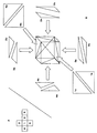
図5Aは、図4の3次元図形のうち出力範囲に含まれるものを2次元平面に投影した図である。図5Aは、視線方向51としたとき、表面が視点側を向くポリゴンのみを描いており、面1、面2、面3の計6つのポリゴンが描かれる。これは、ステップS1で3次元モデルを設定し、視線方向、出力範囲が決定された状態を表す。
FIG. 5A is a diagram in which what is included in the output range of the three-dimensional figure in FIG. 4 is projected onto a two-dimensional plane. FIG. 5A shows only polygons whose surface faces the viewpoint when the line-of-
続いて、メモリ消費量の上限値が決定される(S2)。ここでは、上限値として、ポリゴン数が6個の部分領域を処理するのに必要なメモリ消費量がメモリの空き容量に基づき設定されるものとする。 Subsequently, an upper limit value of the memory consumption is determined (S2). Here, it is assumed that the memory consumption necessary for processing a partial region having six polygons is set as the upper limit value based on the free capacity of the memory.
図5Bは、ステップS3で2次元平面の分割が開始された初期段階を示す図である。図5Bは、図5Aを単純に中央で二分割したものである。図5Bでの分割は、説明を簡単化するために、特にポリゴンの重心を考慮して決定されたものではない。 FIG. 5B is a diagram illustrating an initial stage in which the division of the two-dimensional plane is started in step S3. FIG. 5B is obtained by simply dividing FIG. 5A into two at the center. The division in FIG. 5B is not determined in consideration of the center of gravity of the polygon in order to simplify the explanation.
図3のステップS23、S24においては、こうして分割された各部分領域でのメモリ使用量が算出され、上限値と比較されるが、次のようにすればよい。図5Bにて、右側の部分領域53に含まれるポリゴンは、表面が視点側を向くことを考慮に入れると、ポリゴン1a、ポリゴン1b、ポリゴン2a、ポリゴン2b、ポリゴン3a、ポリゴン3bの6つである。左側の部分領域52の場合、ポリゴン1a、ポリゴン1b、ポリゴン3a、ポリゴン3bの4つであり、右側の部分領域53に含まれるポリゴンの方が左側の部分領域52に含まれるポリゴン数より多い。従って、各部分領域のメモリ使用量のうち最大となるのは右側の部分領域53であり、そのメモリ使用量は、ポリゴン数6個に対応するメモリ使用量として算出される。そこで、図3のステップS24において、部分領域53に含まれるポリゴン数に対応するメモリ消費量が図3のステップS21で決定された上限値を超えるかを判定すればよい。
In steps S23 and S24 in FIG. 3, the memory usage in each of the partial areas thus divided is calculated and compared with the upper limit value. In FIG. 5B, the polygons included in the right
ここでは、部分領域53でのメモリ消費量が上限値と等しく、下回っていないため、分割は十分ではない。そして、図5Bの分割では、分割が十分でないと判定された結果(S5No)、分割が繰り返され、更に分割が進むとする。
Here, since the memory consumption in the
図6Aは、分割が十分でないと判定された結果、更に分割が進んだ状態を示す図であり、図6Bは、図6Aの円に含まれる部分領域54を拡大した図である。図6Aに現されるようになるまで部分領域の分割が進むとすると、図6Aの円に含まれる部分領域54に含まれるポリゴン数が最大で、図6Bに示されるようにそのポリゴン数は5個である。従って、ポリゴン数5個に対応するメモリ消費量がこの時設定されている上限値を下回るので、これ以上の分割はされず(S5Yes)、図6Aが最終的な分割の態様として決定され、その後各部分領域で陰線処理が行われることとなる(S8、S9、S10)。
FIG. 6A is a diagram illustrating a state where the division is further advanced as a result of the determination that the division is not sufficient, and FIG. 6B is an enlarged view of the
なお、図3のステップS21において、上限値は、画像処理装置が自動的に発行するシステムコマンドにより取得されるメモリ空き容量に基づいて決定されたが、操作者が手動でシステムコマンドを発行し、予め画像処理装置に搭載されたメモリ容量を知っており、操作者がその範囲内で上限値を入力設定することも可能である。 In step S21 in FIG. 3, the upper limit value is determined based on the memory free space acquired by the system command automatically issued by the image processing apparatus. However, the operator manually issues the system command, It is also possible to know the memory capacity installed in the image processing apparatus in advance, and the operator can input and set an upper limit value within that range.
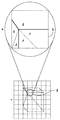
図7Aは、その際表示される設定画面の例である。操作者は、入力装置4を介して、テキストボックス71にメガバイト(MB)単位で数値を入力し、OKボタン72をクリックすれば、その数値が上限値として設定される。図7Aのような設定画面を介して、操作者が自由に上限値を設定することができることにより、操作者の経験や勘を生かしたより柔軟な陰線処理が可能となる。この場合、メモリ搭載量を下回る容量しか入力できないよう設定しておけば、分割後の部分領域にて、メモリ搭載量を上回るメモリが消費されることでスワップが発生することは避けられる。
FIG. 7A is an example of a setting screen displayed at that time. If the operator inputs a numerical value in megabyte (MB) units into the
また、操作者がメモリ消費量と処理速度に関する優先度を選択し、その優先度に基づいて上限値が設定されてもよい。図7Bは、優先度を選択する際に表示される設定画面の例である。操作者は、メモリ消費量を優先させる場合、マウス等の入力装置4を介して、図7Bのスライダーバー73上のポインタ74を左へ移動させ、処理速度を優先させる場合、ポインタ74を右へ移動させる。
Further, the operator may select a priority regarding the memory consumption and the processing speed, and the upper limit value may be set based on the priority. FIG. 7B is an example of a setting screen displayed when the priority is selected. When giving priority to memory consumption, the operator moves the
図8は、優先度の選択を行う場合、その選択より前に、RAM3に予め格納される優先度情報のデータ構成図である。優先度情報には、メモリ消費量を優先させる際の上限値82と、処理速度を優先させる際の上限値81が格納される。なお、処理速度を優先させる際の上限値は、陰線処理実行前のメモリ空き容量に基づいて決定されたものである。メモリ消費量を優先させる際の上限値は、メモリ速度を優先させる際の上限値より少なく設定されるが、これは、図7Aと同様な画面を用いて操作者により入力された数値でも、メモリ空き容量に基づき自動決定される数値(例えば、メモリ空き容量の50%等)が使用されてもよい。モード83には、操作者により選択された優先度が格納され、場合に応じて、メモリ消費量、処理速度、中間が格納される。
FIG. 8 is a data configuration diagram of priority information stored in advance in the
モードが中間とは、図7Bにおいて、メモリ消費量と処理速度の中間が選択された場合であり、この場合にはその相対的な位置によって、上限値を決定する。例えば、メモリ消費量と処理速度の中間地点(50%地点)が選択されれば、150+(200-150)*0.5=175メガバイトを上限値として決定することも可能である。より一般には、メモリ消費量優先時の上限値+(処理速度優先時の上限値−メモリ消費量優先時の上限値)*スライダーバー73上でのポインタ74の相対的位置(割合)で求まる。
The middle mode is a case where the middle of the memory consumption and the processing speed is selected in FIG. 7B. In this case, the upper limit value is determined based on the relative position. For example, if an intermediate point (50% point) between the memory consumption and the processing speed is selected, 150+ (200−150) * 0.5 = 175 megabytes can be determined as the upper limit value. More generally, the upper limit value when the memory consumption is prioritized + (the upper limit value when the processing speed is prioritized−the upper limit value when the memory consumption is prioritized) * the relative position (ratio) of the
メモリ消費量を優先させると、2次元平面がより多くの部分領域に分割される。逆に、処理速度を優先させると、その時点でのRAM3の空き容量を最大容量としてより多くのメモリが陰線処理用に確保されることになる。こうして、RAM3の使用状況に応じて、陰線処理に使用されるメモリ消費量を柔軟に変更することができ、画像処理装置の運用を可能にする。例えば、陰線処理を優先的に行いたい時間帯には、処理速度を優先させ、優先処理に多少の時間がかかることは許容されるが、メモリの消費量を抑えたい時間帯には、メモリ消費量を抑えるといった処理が可能になる。なお、中間地点を選択可能にすることで更に柔軟な上限値の設定が可能になる。
When the memory consumption is prioritized, the two-dimensional plane is divided into more partial areas. On the contrary, if the processing speed is prioritized, more memory is secured for hidden line processing with the free capacity of the
更に、ステップS3において、2次元平面の分割を開始する前に、分割を全く行なわない場合に使用されるメモリ消費量を算出し、すなわち、2次元平面に含まれるすべてのポリゴンをカウントし、それに対応するメモリ消費量を算出し、それを出力装置5に表示することも可能である。その場合、操作者は、画像処理装置のメモリ搭載量と比較することによって、陰線処理を行うにあたり、どれくらいメモリを増設すべきか判断することができ、便利である。
Further, in step S3, before starting the division of the two-dimensional plane, the memory consumption used when no division is performed is calculated, that is, all polygons included in the two-dimensional plane are counted, It is also possible to calculate the corresponding memory consumption and display it on the
以上に述べたように、本実施の形態によれば、まず、上限値が画像処理装置のメモリの搭載量以下に設定され、3次元モデルを投影する2次元平面を部分領域に分割して処理を行う際、各部分領域の陰線処理に必要なメモリ消費量が上限値を下回るため、各部分領域を処理する際にスワップが発生することが防止される。 As described above, according to the present embodiment, first, the upper limit value is set to be equal to or less than the memory capacity of the image processing apparatus, and the two-dimensional plane on which the three-dimensional model is projected is divided into partial areas for processing. Since the memory consumption required for the hidden line processing of each partial area is less than the upper limit value, swapping is prevented when processing each partial area.
そして、上限値は、システムコマンドを利用して自動的に取得可能な空きメモリ容量、操作者により入力される数値のいずれが使用されてもよいため、画像処理装置におけるメモリの使用状況や、画像処理装置のメモリ搭載量に合わせた柔軟な処理が可能である。更に、メモリ消費量と処理速度に関する情報が格納された優先度情報を用いて上限値のより細かい設定制御を行うことも可能になる。更に、2次元平面を分割することなく陰線処理を行うために必要なメモリ量を把握することができ、増設の際の目安となる。 As the upper limit value, any of the free memory capacity that can be automatically acquired using a system command and a numerical value input by an operator may be used. Flexible processing according to the amount of memory installed in the processing device is possible. Furthermore, it becomes possible to perform finer setting control of the upper limit value using priority information in which information on the memory consumption and processing speed is stored. Furthermore, the amount of memory necessary for performing hidden line processing without dividing the two-dimensional plane can be ascertained, which is a measure for expansion.
以上より、本発明によれば、メモリの使用状況やメモリの搭載量に応じて、陰線処理に要するメモリ消費量を最適化し、スワップの発生を防止する陰線処理方法を実現することができる。 As described above, according to the present invention, it is possible to realize a hidden line processing method for optimizing the memory consumption required for the hidden line processing according to the memory usage status and the amount of installed memory and preventing the occurrence of swapping.
以上まとめると付記のようになる。 The above is summarized as an appendix.
(付記1) 画像処理装置において実行され、複数のポリゴンから構成される3次元モデルを2次元平面に投影する際に、前記ポリゴンに隠される線分の投影を回避する陰線処理方法であって、
前記画像処理装置は、前記陰線処理に関するデータと前記陰線処理以外の処理に関するデータを格納するメモリを有しており、
予め、前記メモリの容量のうち前記陰線処理に利用する容量の上限値が設定されており、
前記2次元平面を複数の領域に分割したとき、前記投影された前記3次元モデルのうち前記領域に含まれる部分の前記ポリゴンをそれぞれの領域で抽出し、
前記抽出されたポリゴンに基づき各領域で消費されるメモリ消費量を算出し、
前記算出された領域毎のメモリ消費量の最大値が前記上限値以上の場合、前記2次元平面を更に分割して分割後の領域に投影された前記3次元モデルに含まれる前記ポリゴンの抽出を行い、該抽出されたポリゴンに基づく前記メモリ消費量の算出を繰り返し、
前記算出された領域毎のメモリ消費量の最大値が前記上限値を下回る場合、前記各領域において、前記抽出されたポリゴンに対し陰線処理を行い、領域毎の陰線処理データを作成した後、前記複数の領域の陰線処理データを結合することを特徴とする陰線処理方法。
(Appendix 1) A hidden line processing method that is executed in an image processing apparatus and avoids projection of a line segment hidden by a polygon when a three-dimensional model composed of a plurality of polygons is projected onto a two-dimensional plane,
The image processing apparatus has a memory for storing data relating to the hidden line processing and data relating to processing other than the hidden line processing,
The upper limit value of the capacity used for the hidden line processing is set in advance in the memory capacity,
When the two-dimensional plane is divided into a plurality of regions, the polygons of the portion included in the region of the projected three-dimensional model are extracted in each region,
Calculate the memory consumption consumed in each area based on the extracted polygon,
When the calculated maximum value of memory consumption for each area is equal to or greater than the upper limit value, the polygons included in the three-dimensional model projected on the divided areas after further dividing the two-dimensional plane are extracted. Performing the calculation of the memory consumption based on the extracted polygon,
When the maximum value of the memory consumption for each calculated area is lower than the upper limit value, the hidden polygon processing is performed on the extracted polygon in each area, and the hidden line processing data for each area is created. A hidden line processing method comprising combining hidden line processed data of a plurality of regions.
(付記2) 付記1において、
前記複数の領域への分割は、2分木分割であることを特徴とする陰線処理方法。
(Appendix 2) In
2. The hidden line processing method according to
(付記3) 付記1において、
前記上限値は、前記ポリゴンの抽出前の前記メモリの空き容量に基づき設定されることを特徴とする陰線処理方法。
(Appendix 3) In
The hidden line processing method, wherein the upper limit value is set based on a free space in the memory before the polygon is extracted.
(付記4) 付記1において、
予め、更に、メモリ消費量と処理時間に関する優先度が設定され、
前記処理時間の優先度が前記メモリ消費量の優先度より高い場合、前記上限値は、前記ポリゴンの抽出前の前記メモリの空き容量に基づき設定され、前記処理時間の優先度が前記メモリ消費量の優先度より低い場合、前記上限値は、前記ポリゴンの抽出前の前記メモリの空き容量より少ない容量が設定されることを特徴とする陰線処理方法。
(Appendix 4) In
In addition, priorities for memory consumption and processing time are set in advance.
When the priority of the processing time is higher than the priority of the memory consumption, the upper limit value is set based on the free space of the memory before extraction of the polygon, and the priority of the processing time is set to the memory consumption. In the hidden line processing method, the upper limit value is set to a capacity smaller than a free capacity of the memory before the polygon is extracted.
(付記5) 付記1において、
前記画像処理装置は、更に、前記結合された陰線処理データを表示出力する出力装置が接続され、
分割を行わない場合のメモリ消費量を算出し、前記非分割時のメモリ消費量を前記出力装置を介して表示出力することを特徴とする陰線処理方法。
(Appendix 5) In
The image processing device is further connected to an output device for displaying and outputting the combined hidden line processing data.
A hidden line processing method comprising: calculating a memory consumption amount when no division is performed, and displaying and outputting the memory consumption amount at the time of non-division through the output device.
(付記6) 画像処理装置において、複数のポリゴンから構成される3次元モデルを2次元平面に投影する際に、前記ポリゴンに隠される線分の投影を回避する陰線処理を実行するプログラムであって、
前記画像処理装置は、前記陰線処理に関するデータと前記陰線処理以外の処理に関するデータを格納するメモリを有しており、
予め、前記メモリの容量のうち前記陰線処理に利用する容量の上限値が設定されており、
前記画像処理装置に、
前記2次元平面を複数の領域に分割したとき、前記投影された前記3次元モデルのうち前記領域に含まれる部分の前記ポリゴンをそれぞれの領域で抽出させ、
前記抽出されたポリゴンに基づき各領域で消費されるメモリ消費量を算出させ、
前記算出された領域毎のメモリ消費量の最大値が前記上限値以上の場合、前記2次元平面を更に分割して分割後の領域に投影された前記3次元モデルに含まれる前記ポリゴンの抽出を行い、該抽出されたポリゴンに基づく前記メモリ消費量の算出を繰り返させ、
前記算出された領域毎のメモリ消費量の最大値が前記上限値を下回る場合、前記各領域において、前記抽出されたポリゴンに対し陰線処理を行い、領域毎の陰線処理データを作成した後、前記複数の領域の陰線処理データを結合させることを特徴とするプログラム。
(Additional remark 6) In the image processing apparatus, when projecting a three-dimensional model composed of a plurality of polygons onto a two-dimensional plane, a program for executing hidden line processing for avoiding projection of line segments hidden by the polygons. ,
The image processing apparatus has a memory for storing data relating to the hidden line processing and data relating to processing other than the hidden line processing,
The upper limit value of the capacity used for the hidden line processing is set in advance in the memory capacity,
In the image processing apparatus,
When the two-dimensional plane is divided into a plurality of regions, the polygons of the portion included in the region of the projected three-dimensional model are extracted in each region,
Based on the extracted polygon, the memory consumption consumed in each area is calculated,
When the calculated maximum value of memory consumption for each area is equal to or greater than the upper limit value, the polygons included in the three-dimensional model projected on the divided areas after further dividing the two-dimensional plane are extracted. Performing the calculation of the memory consumption based on the extracted polygon,
When the maximum value of the memory consumption for each calculated area is lower than the upper limit value, the hidden polygon processing is performed on the extracted polygon in each area, and the hidden line processing data for each area is created. A program characterized by combining hidden line processing data of a plurality of areas.
(付記7) 付記6において、
前記複数の領域への分割は、2分木分割であることを特徴とするプログラム。
(Appendix 7) In
A program characterized in that the division into a plurality of areas is binary tree division.
(付記8) 付記6において、
前記上限値は、前記ポリゴンの抽出前の前記メモリの空き容量に基づき設定されることを特徴とするプログラム。
(Appendix 8) In
The program is characterized in that the upper limit value is set based on a free space in the memory before the polygon is extracted.
(付記9) 付記6において、
予め、更に、メモリ消費量と処理時間に関する優先度が設定され、
前記処理時間の優先度が前記メモリ消費量の優先度より高い場合、前記上限値は、前記ポリゴンの抽出前の前記メモリの空き容量に基づき設定され、前記処理時間の優先度が前記メモリ消費量の優先度より低い場合、前記上限値は、前記ポリゴンの抽出前の前記メモリの空き容量より少ない容量が設定されることを特徴とするプログラム。
(Appendix 9) In
In addition, priorities for memory consumption and processing time are set in advance.
When the priority of the processing time is higher than the priority of the memory consumption, the upper limit value is set based on the free space of the memory before extraction of the polygon, and the priority of the processing time is set to the memory consumption. When the priority is lower, the upper limit value is set to a capacity smaller than the free capacity of the memory before extraction of the polygon.
(付記10) 付記6において、
前記画像処理装置は、更に、前記結合された陰線処理データを表示出力する出力装置が接続され、
前記画像処理装置に、分割を行わない場合のメモリ消費量を算出し、前記非分割時のメモリ消費量を前記出力装置を介して表示出力させることを特徴とするプログラム。
(Appendix 10) In
The image processing device is further connected to an output device for displaying and outputting the combined hidden line processing data.
A program characterized in that the image processing device calculates a memory consumption amount when no division is performed, and causes the memory consumption amount at the time of non-division to be displayed and output via the output device.
(付記11) 複数のポリゴンから構成される3次元モデルを2次元平面に投影する際に、前記ポリゴンに隠される線分の投影を回避する陰線処理を行う画像処理装置であって、
画像処理に伴うデータが格納され、予め、前記陰線処理に使用可能な容量の上限値が設定されるメモリと、
前記2次元平面を複数の領域に分割したとき、前記投影された前記3次元モデルのうち前記領域に含まれる部分の前記ポリゴンをそれぞれの領域で抽出し、前記抽出されたポリゴンに基づき各領域で消費されるメモリ消費量を算出し、前記算出された領域毎のメモリ消費量の最大値が前記上限値を下回るまで、前記2次元平面を更に分割して分割後の領域に投影された前記3次元モデルに含まれる前記ポリゴンの抽出を行い、該抽出されたポリゴンに基づく前記メモリ消費量の算出を繰り返すことにより、前記2次元平面の分割の態様を決定する分割態様決定部と、
前記分割態様決定部により決定される分割の態様によって分割された後の前記各領域において、前記抽出されたポリゴンに対し陰線処理を行い領域毎の陰線処理データを作成する陰線処理部と、
前記複数の領域の陰線処理データを結合する結合部とを有することを特徴とする画像処理措置。
(Additional remark 11) When projecting the three-dimensional model comprised of a plurality of polygons onto a two-dimensional plane, an image processing apparatus that performs hidden line processing that avoids projecting line segments hidden by the polygons,
Data associated with image processing is stored, and a memory in which an upper limit value of capacity usable for the hidden line processing is set in advance,
When the two-dimensional plane is divided into a plurality of regions, the polygons included in the regions of the projected three-dimensional model are extracted in the respective regions, and each region is based on the extracted polygons. The consumed memory consumption is calculated, and the two-dimensional plane is further divided and projected onto the divided area until the calculated maximum value of the memory consumption for each area falls below the upper limit value. A division mode determination unit that determines the mode of division of the two-dimensional plane by extracting the polygons included in the three-dimensional model and repeating the calculation of the memory consumption based on the extracted polygons;
A hidden line processing unit that performs hidden line processing on the extracted polygons and generates hidden line processing data for each area in each region after being divided according to the division mode determined by the division mode determination unit;
An image processing measure, comprising: a combining unit that combines the hidden line processing data of the plurality of regions.
(付記12) 付記11において、
前記分割態様決定部は、前記2次元平面を2分木分割することを特徴とする画像処理措置。
(Appendix 12) In
The image processing measure, wherein the division mode determination unit divides the two-dimensional plane into a binary tree.
(付記13) 付記11において、
前記上限値は、前記陰線処理開始前の前記メモリの空き容量が設定されることを特徴とする画像処理装置。
(Appendix 13) In
The image processing apparatus according to
(付記14) 付記11において、
前記メモリに、更に、メモリ消費量と処理時間に関する優先度が設定され、
前記処理時間の優先度が前記メモリ消費量の優先度より高い場合、前記上限値は、前記ポリゴンの抽出前の前記メモリの空き容量に基づき設定され、前記処理時間の優先度が前記メモリ消費量の優先度より低い場合、前記上限値は、前記ポリゴンの抽出前の前記メモリの空き容量より少ない容量が設定されることを特徴とする画像処理装置。
(Appendix 14) In
The memory is further set with priorities for memory consumption and processing time,
When the priority of the processing time is higher than the priority of the memory consumption, the upper limit value is set based on the free space of the memory before extraction of the polygon, and the priority of the processing time is set to the memory consumption. When the priority is lower, the upper limit value is set to a capacity smaller than the free capacity of the memory before the polygon is extracted.
(付記15) 付記11において、
更に、前記結合された陰線処理データを外部表示用に出力する画像表示部を有し、
前記分割態様決定部は、更に、分割を行わない場合のメモリ消費量を算出し、前記非分割時のメモリ消費量を前記画像表示部を介して外部表示用に出力することを特徴とする画像処理装置。
(Appendix 15) In
And an image display unit for outputting the combined hidden line processing data for external display,
The division mode determination unit further calculates a memory consumption amount when the division is not performed, and outputs the memory consumption amount at the time of the non-division for external display via the image display unit. Processing equipment.
1 CPU、2 ROM、3 RAM、4 入力装置、5 出力装置、6 バス 1 CPU, 2 ROM, 3 RAM, 4 input device, 5 output device, 6 buses
Claims (5)
前記画像処理装置は、前記陰線処理に関するデータと前記陰線処理以外の処理に関するデータを格納するメモリを有しており、
予め、前記メモリの容量のうち前記陰線処理に利用する容量の上限値が設定されており、
前記2次元平面を複数の領域に分割したとき、前記投影された前記3次元モデルのうち前記領域に含まれる部分の前記ポリゴンをそれぞれの領域で抽出し、
前記抽出されたポリゴンに基づき各領域で消費されるメモリ消費量を算出し、
前記算出された領域毎のメモリ消費量の最大値が前記上限値以上の場合、前記2次元平面を更に分割して分割後の領域に投影された前記3次元モデルに含まれる前記ポリゴンの抽出を行い、該抽出されたポリゴンに基づく前記メモリ消費量の算出を繰り返し、
前記算出された領域毎のメモリ消費量の最大値が前記上限値を下回る場合、前記各領域において、前記抽出されたポリゴンに対し陰線処理を行い、領域毎の陰線処理データを作成した後、前記複数の領域の陰線処理データを結合することを特徴とする陰線処理方法。 A hidden line processing method that is executed in an image processing apparatus and avoids projection of a line segment hidden by a polygon when projecting a three-dimensional model composed of a plurality of polygons onto a two-dimensional plane,
The image processing apparatus has a memory for storing data relating to the hidden line processing and data relating to processing other than the hidden line processing,
The upper limit value of the capacity used for the hidden line processing is set in advance in the memory capacity,
When the two-dimensional plane is divided into a plurality of regions, the polygons of the portion included in the region of the projected three-dimensional model are extracted in each region,
Calculate the memory consumption consumed in each area based on the extracted polygon,
When the calculated maximum memory consumption for each area is equal to or greater than the upper limit value, the polygons included in the three-dimensional model projected on the divided area after further dividing the two-dimensional plane are extracted. And repeatedly calculating the memory consumption based on the extracted polygons,
When the maximum value of the memory consumption for each calculated area is lower than the upper limit value, the hidden polygon processing is performed on the extracted polygon in each area, and the hidden line processing data for each area is created. A hidden line processing method comprising combining hidden line processed data of a plurality of regions.
前記上限値は、前記ポリゴンの抽出前の前記メモリの空き容量に基づき設定されることを特徴とする陰線処理方法。 In claim 1,
The hidden line processing method, wherein the upper limit value is set based on a free space in the memory before the polygon is extracted.
予め、更に、メモリ消費量と処理時間に関する優先度が設定され、
前記処理時間の優先度が前記メモリ消費量の優先度より高い場合、前記上限値は、前記ポリゴンの抽出前の前記メモリの空き容量に基づき設定され、前記処理時間の優先度が前記メモリ消費量の優先度より低い場合、前記上限値は、前記ポリゴンの抽出前の前記メモリの空き容量より少ない容量が設定されることを特徴とする陰線処理方法。 In claim 1,
In addition, priorities for memory consumption and processing time are set in advance.
When the priority of the processing time is higher than the priority of the memory consumption, the upper limit value is set based on the free space of the memory before extraction of the polygon, and the priority of the processing time is set to the memory consumption. In the hidden line processing method, the upper limit value is set to a capacity smaller than a free capacity of the memory before the polygon is extracted.
前記画像処理装置は、前記陰線処理に関するデータと前記陰線処理以外の処理に関するデータを格納するメモリを有しており、
予め、前記メモリの容量のうち前記陰線処理に利用する容量の上限値が設定されており、
前記画像処理装置に、
前記2次元平面を複数の領域に分割したとき、前記投影された前記3次元モデルのうち前記領域に含まれる部分の前記ポリゴンをそれぞれの領域で抽出させ、
前記抽出されたポリゴンに基づき各領域で消費されるメモリ消費量を算出させ、
前記算出された領域毎のメモリ消費量の最大値が前記上限値以上の場合、前記2次元平面を更に分割して分割後の領域に投影された前記3次元モデルに含まれる前記ポリゴンの抽出を行い、該抽出されたポリゴンに基づく前記メモリ消費量の算出を繰り返させ、
前記算出された領域毎のメモリ消費量の最大値が前記上限値を下回る場合、前記各領域において、前記抽出されたポリゴンに対し陰線処理を行い、領域毎の陰線処理データを作成した後、前記複数の領域の陰線処理データを結合させることを特徴とするプログラム。 In the image processing apparatus, when projecting a three-dimensional model composed of a plurality of polygons onto a two-dimensional plane, a program that executes hidden line processing that avoids projecting line segments hidden by the polygons,
The image processing apparatus has a memory for storing data relating to the hidden line processing and data relating to processing other than the hidden line processing,
The upper limit value of the capacity used for the hidden line processing is set in advance in the memory capacity,
In the image processing apparatus,
When the two-dimensional plane is divided into a plurality of regions, the polygons of the portion included in the region of the projected three-dimensional model are extracted in each region,
Based on the extracted polygon, the memory consumption consumed in each area is calculated,
When the calculated maximum value of memory consumption for each area is equal to or greater than the upper limit value, the polygons included in the three-dimensional model projected on the divided areas after further dividing the two-dimensional plane are extracted. Performing the calculation of the memory consumption based on the extracted polygon,
When the maximum value of the memory consumption for each calculated area is lower than the upper limit value, the hidden polygon processing is performed on the extracted polygon in each area, and the hidden line processing data for each area is created. A program characterized by combining hidden line processing data of a plurality of areas.
画像処理に伴うデータが格納され、予め、前記陰線処理に使用可能な容量の上限値が設定されるメモリと、
前記2次元平面を複数の領域に分割したとき、前記投影された前記3次元モデルのうち前記領域に含まれる部分の前記ポリゴンをそれぞれの領域で抽出し、前記抽出されたポリゴンに基づき各領域で消費されるメモリ消費量を算出し、前記算出された領域毎のメモリ消費量の最大値が前記上限値を下回るまで、前記2次元平面を更に分割して分割後の領域に投影された前記3次元モデルに含まれる前記ポリゴンの抽出を行い、該抽出されたポリゴンに基づく前記メモリ消費量の算出を繰り返すことにより、前記2次元平面の分割の態様を決定する分割態様決定部と、
前記分割態様決定部により決定される分割の態様によって分割された後の前記各領域において、前記抽出されたポリゴンに対し陰線処理を行い領域毎の陰線処理データを作成する陰線処理部と、
前記複数の領域の陰線処理データを結合する結合部とを有することを特徴とする画像処理措置。 An image processing apparatus that performs hidden line processing to avoid projection of a line segment hidden by a polygon when projecting a three-dimensional model composed of a plurality of polygons onto a two-dimensional plane,
Data associated with image processing is stored, and a memory in which an upper limit value of capacity usable for the hidden line processing is set in advance,
When the two-dimensional plane is divided into a plurality of regions, the polygons included in the regions of the projected three-dimensional model are extracted in the respective regions, and each region is based on the extracted polygons. The consumed memory consumption is calculated, and the two-dimensional plane is further divided and projected onto the divided area until the calculated maximum value of the memory consumption for each area falls below the upper limit value. A division mode determination unit that determines the mode of division of the two-dimensional plane by extracting the polygons included in the three-dimensional model and repeating the calculation of the memory consumption based on the extracted polygons;
A hidden line processing unit that performs hidden line processing on the extracted polygons and generates hidden line processing data for each area in each region after being divided according to the division mode determined by the division mode determination unit;
An image processing measure, comprising: a combining unit that combines the hidden line processing data of the plurality of regions.
Priority Applications (2)
| Application Number | Priority Date | Filing Date | Title |
|---|---|---|---|
| JP2004110994A JP4364706B2 (en) | 2004-04-05 | 2004-04-05 | Hidden line processing method |
| US10/967,640 US7518607B2 (en) | 2004-04-05 | 2004-10-19 | Hidden-line removal method |
Applications Claiming Priority (1)
| Application Number | Priority Date | Filing Date | Title |
|---|---|---|---|
| JP2004110994A JP4364706B2 (en) | 2004-04-05 | 2004-04-05 | Hidden line processing method |
Publications (2)
| Publication Number | Publication Date |
|---|---|
| JP2005293467A true JP2005293467A (en) | 2005-10-20 |
| JP4364706B2 JP4364706B2 (en) | 2009-11-18 |
Family
ID=35053745
Family Applications (1)
| Application Number | Title | Priority Date | Filing Date |
|---|---|---|---|
| JP2004110994A Expired - Fee Related JP4364706B2 (en) | 2004-04-05 | 2004-04-05 | Hidden line processing method |
Country Status (2)
| Country | Link |
|---|---|
| US (1) | US7518607B2 (en) |
| JP (1) | JP4364706B2 (en) |
Cited By (4)
| Publication number | Priority date | Publication date | Assignee | Title |
|---|---|---|---|---|
| US8587592B2 (en) | 2009-10-20 | 2013-11-19 | Samsung Electronics Co., Ltd. | Tile-based rendering apparatus and method |
| JP2016056665A (en) * | 2014-09-12 | 2016-04-21 | 株式会社ア−キテック | Device and program for reinforcing bar arrangement verification support |
| JP2017213047A (en) * | 2016-05-30 | 2017-12-07 | 株式会社オリンピア | Game machine |
| CN113628102A (en) * | 2021-08-16 | 2021-11-09 | 广东三维家信息科技有限公司 | Entity model blanking method and device, electronic equipment and storage medium |
Families Citing this family (5)
| Publication number | Priority date | Publication date | Assignee | Title |
|---|---|---|---|---|
| SE0601135L (en) * | 2006-05-22 | 2007-08-14 | Xcounter Ab | Apparatus and method for creating tomosynthesis and projection images |
| SE0702061L (en) * | 2007-09-17 | 2009-03-18 | Xcounter Ab | Method for creating, displaying and analyzing X-rays and device for implementing the method |
| SE0702258L (en) * | 2007-10-09 | 2009-03-31 | Xcounter Ab | Device and method for recording radiation image data of an object |
| CN102654849A (en) * | 2011-03-03 | 2012-09-05 | 赛酷特(北京)信息技术有限公司 | Method for hiding and reading by partitions |
| CN102902499B (en) * | 2012-08-22 | 2015-06-03 | 华为技术有限公司 | Partition display method and device of storage device |
Family Cites Families (21)
| Publication number | Priority date | Publication date | Assignee | Title |
|---|---|---|---|---|
| US3602702A (en) * | 1969-05-19 | 1971-08-31 | Univ Utah | Electronically generated perspective images |
| US3889107A (en) * | 1972-10-16 | 1975-06-10 | Evans & Sutherland Computer Co | System of polygon sorting by dissection |
| US4694404A (en) * | 1984-01-12 | 1987-09-15 | Key Bank N.A. | High-speed image generation of complex solid objects using octree encoding |
| US5086496A (en) * | 1988-05-02 | 1992-02-04 | Arch Development Corporation | Method for hidden line and surface removal in a three dimensional display |
| JPH0792838B2 (en) | 1989-12-28 | 1995-10-09 | インターナショナル・ビジネス・マシーンズ・コーポレーション | Three-dimensional graphic display method and system |
| US5729672A (en) * | 1993-07-30 | 1998-03-17 | Videologic Limited | Ray tracing method and apparatus for projecting rays through an object represented by a set of infinite surfaces |
| US5579455A (en) * | 1993-07-30 | 1996-11-26 | Apple Computer, Inc. | Rendering of 3D scenes on a display using hierarchical z-buffer visibility |
| JP2862465B2 (en) | 1993-09-22 | 1999-03-03 | 株式会社ノリタケカンパニーリミテド | Heating roller for fixing toner |
| JP2882465B2 (en) | 1995-12-25 | 1999-04-12 | 日本電気株式会社 | Image generation method and apparatus |
| JPH10134204A (en) | 1996-10-28 | 1998-05-22 | Hitachi Ltd | Graphics display |
| US5977980A (en) * | 1997-07-14 | 1999-11-02 | Ati Technologies | Method and apparatus for determining visibility of a pixel |
| US6525726B1 (en) * | 1999-11-02 | 2003-02-25 | Intel Corporation | Method and apparatus for adaptive hierarchical visibility in a tiled three-dimensional graphics architecture |
| GB0124630D0 (en) * | 2001-10-13 | 2001-12-05 | Picsel Res Ltd | "Systems and methods for generating visual representations of graphical data and digital document processing" |
| US6897863B2 (en) * | 2001-11-30 | 2005-05-24 | Caterpillar Inc | System and method for hidden object removal |
| US6999091B2 (en) * | 2001-12-28 | 2006-02-14 | Intel Corporation | Dual memory channel interleaving for graphics and video |
| US20030122820A1 (en) * | 2001-12-31 | 2003-07-03 | Doyle Peter L. | Object culling in zone rendering |
| AUPS028702A0 (en) * | 2002-02-01 | 2002-02-28 | Canon Kabushiki Kaisha | Efficient display update from changing object graphics |
| US7002571B2 (en) * | 2002-06-04 | 2006-02-21 | Intel Corporation | Grid-based loose octree for spatial partitioning |
| US6911983B2 (en) * | 2003-03-12 | 2005-06-28 | Nvidia Corporation | Double-buffering of pixel data using copy-on-write semantics |
| JP4390574B2 (en) * | 2003-03-31 | 2009-12-24 | 富士通株式会社 | Hidden line processing method for eliminating hidden lines when projecting a 3D model composed of a plurality of polygons onto a 2D plane |
| US7164420B2 (en) * | 2003-07-24 | 2007-01-16 | Autodesk, Inc. | Ray tracing hierarchy |
-
2004
- 2004-04-05 JP JP2004110994A patent/JP4364706B2/en not_active Expired - Fee Related
- 2004-10-19 US US10/967,640 patent/US7518607B2/en not_active Expired - Fee Related
Cited By (5)
| Publication number | Priority date | Publication date | Assignee | Title |
|---|---|---|---|---|
| US8587592B2 (en) | 2009-10-20 | 2013-11-19 | Samsung Electronics Co., Ltd. | Tile-based rendering apparatus and method |
| JP2016056665A (en) * | 2014-09-12 | 2016-04-21 | 株式会社ア−キテック | Device and program for reinforcing bar arrangement verification support |
| JP2017213047A (en) * | 2016-05-30 | 2017-12-07 | 株式会社オリンピア | Game machine |
| CN113628102A (en) * | 2021-08-16 | 2021-11-09 | 广东三维家信息科技有限公司 | Entity model blanking method and device, electronic equipment and storage medium |
| CN113628102B (en) * | 2021-08-16 | 2024-09-10 | 广东三维家信息科技有限公司 | Entity model blanking method and device, electronic equipment and storage medium |
Also Published As
| Publication number | Publication date |
|---|---|
| JP4364706B2 (en) | 2009-11-18 |
| US20050219243A1 (en) | 2005-10-06 |
| US7518607B2 (en) | 2009-04-14 |
Similar Documents
| Publication | Publication Date | Title |
|---|---|---|
| US11270506B2 (en) | Foveated geometry tessellation | |
| US8325177B2 (en) | Leveraging graphics processors to optimize rendering 2-D objects | |
| US7307628B1 (en) | Diamond culling of small primitives | |
| KR100907154B1 (en) | Image processing device and its components, rendering method | |
| JP6360567B2 (en) | Information processing apparatus and information processing method | |
| EP3567550A1 (en) | Image processing apparatus, control method of image processing apparatus, and computer-readable storage medium | |
| EP1287494A1 (en) | Tiling and compression for rendering 3d images | |
| KR20110093404A (en) | 3D graphics rendering device and method | |
| JP4364706B2 (en) | Hidden line processing method | |
| JPH11259671A (en) | Image display method and image display device executing the same | |
| CN100354891C (en) | An improved method and device for template shadow cone operation | |
| US12272000B2 (en) | Hierarchical depth data generation using primitive fusion | |
| KR102225281B1 (en) | Techniques for reduced pixel shading | |
| JP5304443B2 (en) | Drawing data processing method, drawing system, and drawing data creation program | |
| JP3756888B2 (en) | Graphics processor, graphics card and graphics processing system | |
| JP6590606B2 (en) | Image processing apparatus, image processing method, and program | |
| JP2001184373A (en) | Drawing generation method and system, and computer-readable recording medium recording a drawing generation program for generating a two-dimensional drawing from three-dimensional model data | |
| US9177354B2 (en) | Rendering apparatus, rendering method, and computer product | |
| JP2010146250A (en) | Device, method and program for dividing curve, recording medium recorded with program for dividing curve, and integrated circuit for dividing curve | |
| US20230419597A1 (en) | Binning pass with hierarchical depth data determination | |
| US11132168B2 (en) | Display method, display device, and display program | |
| US20220262053A1 (en) | Image processing apparatus, image processing method, and program | |
| JPH08185542A (en) | Graphic processor | |
| JP4610394B2 (en) | Z sort processing circuit and three-dimensional image drawing apparatus using the same | |
| JP4681929B2 (en) | Image processing method and image processing apparatus |
Legal Events
| Date | Code | Title | Description |
|---|---|---|---|
| A621 | Written request for application examination |
Free format text: JAPANESE INTERMEDIATE CODE: A621 Effective date: 20061027 |
|
| A977 | Report on retrieval |
Free format text: JAPANESE INTERMEDIATE CODE: A971007 Effective date: 20090615 |
|
| A131 | Notification of reasons for refusal |
Free format text: JAPANESE INTERMEDIATE CODE: A131 Effective date: 20090623 |
|
| A521 | Written amendment |
Free format text: JAPANESE INTERMEDIATE CODE: A523 Effective date: 20090722 |
|
| TRDD | Decision of grant or rejection written | ||
| A01 | Written decision to grant a patent or to grant a registration (utility model) |
Free format text: JAPANESE INTERMEDIATE CODE: A01 Effective date: 20090818 |
|
| A01 | Written decision to grant a patent or to grant a registration (utility model) |
Free format text: JAPANESE INTERMEDIATE CODE: A01 |
|
| A61 | First payment of annual fees (during grant procedure) |
Free format text: JAPANESE INTERMEDIATE CODE: A61 Effective date: 20090819 |
|
| FPAY | Renewal fee payment (event date is renewal date of database) |
Free format text: PAYMENT UNTIL: 20120828 Year of fee payment: 3 |
|
| R150 | Certificate of patent or registration of utility model |
Free format text: JAPANESE INTERMEDIATE CODE: R150 |
|
| FPAY | Renewal fee payment (event date is renewal date of database) |
Free format text: PAYMENT UNTIL: 20120828 Year of fee payment: 3 |
|
| FPAY | Renewal fee payment (event date is renewal date of database) |
Free format text: PAYMENT UNTIL: 20130828 Year of fee payment: 4 |
|
| LAPS | Cancellation because of no payment of annual fees |