JP2005293408A - Electronic device apparatus, server apparatus, control method and program thereof - Google Patents
Electronic device apparatus, server apparatus, control method and program thereof Download PDFInfo
- Publication number
- JP2005293408A JP2005293408A JP2004110089A JP2004110089A JP2005293408A JP 2005293408 A JP2005293408 A JP 2005293408A JP 2004110089 A JP2004110089 A JP 2004110089A JP 2004110089 A JP2004110089 A JP 2004110089A JP 2005293408 A JP2005293408 A JP 2005293408A
- Authority
- JP
- Japan
- Prior art keywords
- rhythm pattern
- information
- pattern information
- user
- information processing
- Prior art date
- Legal status (The legal status is an assumption and is not a legal conclusion. Google has not performed a legal analysis and makes no representation as to the accuracy of the status listed.)
- Pending
Links
Images


Landscapes
- Input From Keyboards Or The Like (AREA)
- Details Of Television Systems (AREA)
- Selective Calling Equipment (AREA)
Abstract
【課題】
複雑な登録作業や特殊な入力デバイスによる操作をしなくとも、単純な入力操作により複雑な機能を呼び出すことができ、かつユーザがその操作を直感的に記憶して実行することができる電子機器装置、サーバ装置、制御方法及び提供すること。
【解決手段】
ユーザの操作による一連の入力信号のリズムパターンを、ユーザが指定した機能コマンドと対応付けて予め記憶し、再度ユーザが操作を行って入力信号が入力されたときに、その入力信号のリズムパターンと上記記憶したリズムパターンとを比較して、両者が同一または類似の場合に、当該リズムパターンに対応する上記機能コマンドを実行させることとした。
【選択図】 図5
【Task】
An electronic device that can call complicated functions by a simple input operation without complicated registration work or operation by a special input device, and allows the user to intuitively store and execute the operation , Server apparatus, control method, and provision.
[Solution]
A rhythm pattern of a series of input signals by a user's operation is stored in advance in association with a function command designated by the user, and when the input signal is input when the user performs an operation again, the rhythm pattern of the input signal The stored rhythm pattern is compared, and when both are the same or similar, the function command corresponding to the rhythm pattern is executed.
[Selection] Figure 5
Description
本発明は、入力信号のリズムパターンに応じて各種の制御命令を実行することが可能な電子機器装置、サーバ装置、制御方法及びそのプログラムに関する。 The present invention relates to an electronic apparatus device, a server device, a control method, and a program thereof that can execute various control commands in accordance with a rhythm pattern of an input signal.
電子機器等に様々な命令を実行させる際、当該電子機器の機能が多様化するほどその命令入力方法も複雑になる傾向がある。特に近年においては、PC(Personal Computer)等の情報処理装置や携帯電話等が多機能化し、ユーザは目的の機能を実行するために多くの複雑な操作手続を踏まなくてはならなかったり、特別な入力デバイス等を搭載しなければならなかったりするという問題がある。 When an electronic device or the like executes various commands, the command input method tends to become more complicated as the functions of the electronic device become more diversified. In particular, in recent years, information processing devices such as PCs (Personal Computers) and mobile phones have become multifunctional, and users have to go through a lot of complicated operating procedures in order to execute the desired functions. There is a problem that it is necessary to install an input device or the like.
そこで、複数の操作手続を単純化するために、従来から採られている手法として、短縮コマンドやショートカット機能といった技術が存在する。短縮コマンドの例としては、電話において、電話番号を入力して発信するという一連の操作を一つのボタンに登録して当該ボタンの押下により実行可能にするという機能があり、またショートカット機能の例としては、PCの階層ファイルシステムの奥深い領域に格納されたデータに直接アクセスするためのショートカットアイコン等を提供するMicrosoft Windows(登録商標)等のショートカット機能がある。(例えば、非特許文献1参照)。
しかしながら、上述の電話の例においては、ユーザはどの短縮ボタンにどの電話番号の発信機能を登録したかを覚えておく必要があり、登録作業には登録ボタンなどを駆使して複雑な作業を予め行う必要がある。また、上述のショートカット機能の例においては、ショートカットアイコンのようなGUI(Graphical User Interface)が提供されて初めて実現できる機能であり、マウス等を駆使した登録作業もPCに不慣れなユーザにとっては難しく、ショートカット機能の概念を理解すること自体も困難である。 However, in the above telephone example, it is necessary for the user to remember which telephone number has a dialing function registered to which abbreviated button. There is a need to do. Moreover, in the example of the shortcut function described above, it is a function that can be realized only when a GUI (Graphical User Interface) such as a shortcut icon is provided, and registration work using a mouse or the like is difficult for a user unfamiliar with the PC, It is difficult to understand the concept of the shortcut function.
更に、操作する電子機器や入力デバイスの大きさが小さい場合には、様々な操作が不便になることが多い。よって、例えば画面上にリストアップされた多数の項目から一つを選択するような操作を行う場合には、テレビリモコン等においては上下左右のカーソルキーを搭載したり、携帯電話等においてはジョグダイヤルを搭載したりするなど、ユーザの操作を簡便にしようとすると、特殊な入力デバイスを追加する必要がある場合が多い。 Furthermore, various operations are often inconvenient when the size of the electronic device or input device to be operated is small. Thus, for example, when performing an operation for selecting one of many items listed on the screen, the TV remote control or the like is equipped with cursor keys for up / down / left / right or the mobile phone or the like with a jog dial. In order to simplify user operations such as mounting, it is often necessary to add a special input device.
以上のような事情に鑑み、本発明の目的は、複雑な登録作業や特殊な入力デバイスによる操作をしなくとも、単純な入力操作により複雑な機能を呼び出すことができ、かつユーザがその操作を直感的に記憶して実行することができる電子機器装置、サーバ装置、制御方法及びそのプログラムを提供することにある。 In view of the circumstances as described above, the object of the present invention is to call a complicated function by a simple input operation without performing complicated registration work or operation by a special input device, and the user can perform the operation. An object of the present invention is to provide an electronic device device, a server device, a control method, and a program thereof that can be stored and executed intuitively.
上述の課題を解決するため、本発明の電子機器装置は、ユーザの操作による一連の入力信号を検出する第1の検出手段と、前記検出された入力信号のリズムパターン情報を、ユーザが指定した制御命令情報と対応付けて記憶する記憶手段と、前記リズムパターン情報の記憶後のユーザの操作による入力信号を検出する第2の検出手段と、前記第2の入力手段により検出された入力信号のリズムパターン情報と前記記憶されたリズムパターン情報とを比較する比較手段と、前記比較手段により、上記両リズムパターン情報が同一または類似であると判断された場合に、前記記憶された制御命令情報を基に、前記記憶されたリズムパターン情報に対応する制御命令を実行する実行手段とを具備することを特徴としている。 In order to solve the above-described problems, an electronic device device according to the present invention specifies a first detection unit that detects a series of input signals by a user operation and rhythm pattern information of the detected input signals by a user. Storage means for storing in association with control command information; second detection means for detecting an input signal by a user operation after storing the rhythm pattern information; and an input signal detected by the second input means. Comparing means for comparing rhythm pattern information with the stored rhythm pattern information, and when the comparing means determines that the rhythm pattern information is the same or similar, the stored control command information is And an execution means for executing a control command corresponding to the stored rhythm pattern information.
ここでユーザの操作とは、例えばプッシュボタン、キーボード、タッチパネル等の入力デバイスによる押下操作や、マウスを動かしたり、ジョグダイヤルを回したりする操作をいい、一連の入力信号とは、例えば各入力信号間の時間間隔が0.5秒から1秒以内の場合等、短い間隔の信号をいう。 Here, the user operation refers to a pressing operation using an input device such as a push button, a keyboard, or a touch panel, or an operation of moving a mouse or turning a jog dial. A series of input signals is, for example, between input signals. A signal with a short interval such as when the time interval is within 0.5 seconds to 1 second.
また制御命令とは、例えば上記電子機器装置がHDD(Hard Disk Drive)レコーダやオーディオプレーヤの場合には、動画や音楽の再生、一時停止等を実行させる命令をいい、携帯電話の場合には、所望の相手に電話をかける動作を実行させる命令等をいう。 The control command is, for example, a command to execute playback or pause of a video or music when the electronic device is an HDD (Hard Disk Drive) recorder or an audio player, and in the case of a mobile phone, A command or the like for executing a call to a desired party.
上記リズムとは、例えばユーザが行った一連のボタン押下操作における押下のタイミングを示した「トトントントトン」、「トントトントトン」等の調子をいう。また上記類似とは、例えばリズムパターンが同一でテンポが異なる場合や、テンポが同一で、リズムパターンも例えば100分の1秒から10分の1秒程度の差異しかない場合等、ほぼ同一に近い場合をいう。 The rhythm refers to a tone such as “ton-ton-ton-ton” or “ton-ton-ton-ton” indicating the timing of pressing in a series of button pressing operations performed by the user. Also, the above similarity is almost the same, for example, when the rhythm pattern is the same and the tempo is different, or when the tempo is the same and the rhythm pattern is only a difference of 1/100 second to 1/10 second, for example. Refers to cases.
この構成により、上記ユーザの操作による一連の入力信号のリズムパターン情報を、ユーザが指定した制御命令情報と対応付けて予め記憶し、再度ユーザが操作を行って入力信号が入力されたときに、その入力信号のリズムパターン情報と上記記憶したリズムパターン情報とを比較して、両者が同一または類似の場合に当該リズムパターン情報に対応する上記制御命令を実行させることとしたため、ユーザは自らの意思により上記リズムパターンと制御命令とを対応付けて直感的に記憶しておくことができ、当該リズムパターンの入力という単純な入力操作により上記制御命令を容易に実行させることができる。 With this configuration, the rhythm pattern information of a series of input signals by the user's operation is stored in advance in association with the control command information specified by the user, and when the user performs an operation again and the input signal is input, The rhythm pattern information of the input signal is compared with the stored rhythm pattern information, and when both are the same or similar, the control command corresponding to the rhythm pattern information is executed. Thus, the rhythm pattern and the control command can be associated and stored intuitively, and the control command can be easily executed by a simple input operation of inputting the rhythm pattern.
上記電子機器装置において、前記記憶手段は、前記リズムパターン情報として、前記第1の検出手段により検出された入力信号の数情報、各入力信号間の時間間隔情報及び入力信号の総時間情報を記憶するようにしてもよい。これらの情報を上記リズムパターンのパラメータとすることで、様々なリズムパターンを一元的に記憶し、検出することができる。 In the electronic apparatus, the storage unit stores, as the rhythm pattern information, number information of input signals detected by the first detection unit, time interval information between the input signals, and total time information of the input signals. You may make it do. By using these pieces of information as parameters of the rhythm pattern, various rhythm patterns can be stored and detected centrally.
ところで、上記リズムパターンの入力毎に同一のテンポで入力することはユーザにとって困難であるため、上記記憶したリズムパターンと、その後にユーザが入力するリズムパターンが同一または類似でも、入力毎にテンポが異なる場合が想定される。よって、それにより両者が非類似と判断されてしまうと、上記制御命令が実行できないことになる。 By the way, since it is difficult for the user to input at the same tempo for each input of the rhythm pattern, even if the stored rhythm pattern and the rhythm pattern input by the user thereafter are the same or similar, the tempo is increased for each input. Different cases are assumed. Thus, if it is determined that the two are dissimilar, the control command cannot be executed.
そこで、上記電子機器装置において、前記判断手段は、前記記憶手段により記憶されたリズムパターン情報と、前記第2の検出手段により検出されたリズムパターン情報とをそれぞれのリズムパターン情報に含まれる総時間情報により正規化したした上で両者を比較することにより類似を判断するようにしてもよい。 Therefore, in the electronic device, the determination unit includes the rhythm pattern information stored in the storage unit and the rhythm pattern information detected by the second detection unit in each rhythm pattern information. You may make it judge similarity by comparing both after normalizing by information.
ここで正規化とは、上記各リズムパターン情報をそれぞれの総時間情報により除算して、各リズムパターン情報をそれぞれ一定の時間当たりにおける情報に変形して統一することをいう。 Here, normalization means that each rhythm pattern information is divided by each total time information, and each rhythm pattern information is transformed into information per fixed time and unified.
これにより、予め記憶したリズムパターンと、その後に入力されたリズムパターンを、それぞれの上記総時間により正規化することで、両者のテンポが異なっていても、リズムパターン自体が同一または類似であれば、両者は類似と判断されるため、ユーザが意図しない微妙なリズムパターンの違いにより制御命令が実行されないことを防止することができる。 As a result, the rhythm pattern stored in advance and the rhythm pattern input thereafter are normalized by the total time, so that even if the tempo of both is different, the rhythm pattern itself is the same or similar. Since both are judged to be similar, it is possible to prevent the control command from being executed due to a subtle difference in rhythm pattern not intended by the user.
前記電子機器装置において、前記記憶手段により記憶されたリズムパターン情報は、前記ユーザが指定した制御命令から連想されるイメージと関連していてもよい。これにより、ユーザは上記リズムパターンと上記制御命令を自己の意思で関連付けることができ、またその関連付けを直感的に覚えておくことができるため、当該対応関係を苦労して覚える必要も無く、容易に制御命令を実行させることができる。 In the electronic device, the rhythm pattern information stored by the storage unit may be associated with an image associated with a control command designated by the user. As a result, the user can associate the rhythm pattern and the control command with his / her own intention, and can easily remember the association, so there is no need to learn the corresponding relationship easily and easily. Can execute control instructions.
上記電子機器装置において、前記ユーザの操作は、ボタンまたはキーボードの押下操作であってもよい。これにより、ユーザはリモートコントローラ等のボタンまたはキーボードの押下操作により上記リズムパターンを入力して上記制御命令と対応付けて記憶させ、再度当該リズムパターンを入力することにより上記制御命令を容易に実行させることができる。 In the electronic apparatus, the user operation may be a button or keyboard pressing operation. As a result, the user inputs the rhythm pattern by pressing the button of the remote controller or the keyboard or the keyboard, stores the rhythm pattern in association with the control command, and easily executes the control command by inputting the rhythm pattern again. be able to.
本発明のサーバ装置は、ユーザの操作による一連の入力信号のリズムパターン情報を、ユーザが指定した制御命令情報及び制御対象の機器に関する機器情報と対応付けて記憶する記憶手段と、前記リズムパターン情報の記憶後のユーザの操作による入力信号のリズムパターン情報を受信する受信手段と、前記受信されたリズムパターン情報と前記記憶されたリズムパターン情報とを比較する比較手段と、前記比較手段により、上記両リズムパターン情報が同一または類似であると判断された場合に、前記記憶された制御命令情報及び機器情報を基に、前記記憶されたリズムパターン情報に対応する制御命令を前記制御対象の機器へ送信する送信手段とを具備することを特徴としている。 The server device according to the present invention includes a storage unit that stores rhythm pattern information of a series of input signals generated by a user operation in association with control command information specified by a user and device information related to a device to be controlled, and the rhythm pattern information Receiving means for receiving the rhythm pattern information of the input signal by the user's operation after storing, comparing means for comparing the received rhythm pattern information with the stored rhythm pattern information, and the comparing means, When it is determined that both rhythm pattern information is the same or similar, based on the stored control command information and device information, a control command corresponding to the stored rhythm pattern information is sent to the device to be controlled. And transmitting means for transmitting.
上記機器とは、例えば各種AV(Audio and Visual)機器、テレビ、HDDレコーダ等の家電機器である。 The devices are, for example, home appliances such as various AV (Audio and Visual) devices, televisions, and HDD recorders.
この構成により、上記制御対象の機器に制御命令を実行させるためのリズムパターン情報を、当該制御命令情報及び上記機器情報と対応付けて記憶しておき、上記リズムパターンを受信した場合にそれに対応する制御命令を上記制御対象の機器に転送することができるため、例えばユーザが制御対象の機器の近隣に存在せず、直接当該機器を操作することができない場合でも、ユーザの代わりに当該機器に上記制御命令を転送することで、当該機器を制御することが可能となる。 With this configuration, rhythm pattern information for causing the device to be controlled to execute a control command is stored in association with the control command information and the device information, and when the rhythm pattern is received, it corresponds to that. Since the control command can be transferred to the device to be controlled, for example, even when the user does not exist in the vicinity of the device to be controlled and cannot directly operate the device, The device can be controlled by transferring the control command.
また、例えば上記制御対象の機器の記憶容量が小さく、上記リズムパターン情報及び上記制御命令情報を記憶することができない場合に、当該機器の代わりにそれらの情報を記憶して、当該機器に対するリズムパターンの入力があった場合にそれに対応する制御命令を検索して当該機器に送信することにより、当該機器を制御させることも可能となる。 For example, when the storage capacity of the device to be controlled is small and the rhythm pattern information and the control command information cannot be stored, the information is stored instead of the device, and the rhythm pattern for the device is stored. If the control command corresponding to the input is retrieved and transmitted to the device, the device can be controlled.
本発明の主たる観点に係る制御方法は、ユーザの操作を入力するステップと、前記入力された操作のリズムパターン情報を、ユーザが指定した制御命令情報と対応付けて記憶するステップと、前記リズムパターン情報の記憶後のユーザの操作を入力するステップと、前記リズムパターン情報の記憶後に入力された操作のリズムパターン情報と前記記憶されたリズムパターン情報とを比較するステップと、前記比較の結果、上記両リズムパターン情報が同一または類似であると判断された場合に、前記記憶された制御命令情報を基に、前記記憶されたリズムパターン情報に対応する制御命令を実行するステップとを具備することを特徴としている。 The control method according to the main aspect of the present invention includes a step of inputting a user's operation, a step of storing rhythm pattern information of the input operation in association with control command information designated by the user, and the rhythm pattern A step of inputting a user operation after storing the information, a step of comparing the rhythm pattern information of the operation input after storing the rhythm pattern information with the stored rhythm pattern information, and the result of the comparison, A step of executing a control command corresponding to the stored rhythm pattern information based on the stored control command information when it is determined that both rhythm pattern information are the same or similar. It is a feature.
また、本発明の他の観点に係る制御方法は、ユーザにより入力された操作のリズムパターン情報を、ユーザが指定した制御命令情報及び制御対象の機器に関する機器情報と対応付けて記憶するステップと、前記リズムパターン情報の記憶後のユーザの操作のリズムパターン情報を受信するステップと、前記受信されたリズムパターン情報と前記記憶されたリズムパターン情報とを比較するステップと、前記比較の結果、上記両リズムパターン情報が同一または類似であると判断された場合に、前記記憶された制御命令情報及び機器情報を基に、前記記憶されたリズムパターン情報に対応する制御命令を前記制御対象の機器へ送信するステップとを具備することを特徴としている。 Further, the control method according to another aspect of the present invention stores the rhythm pattern information of the operation input by the user in association with the control command information specified by the user and the device information regarding the device to be controlled, Receiving the rhythm pattern information of the user's operation after storing the rhythm pattern information; comparing the received rhythm pattern information with the stored rhythm pattern information; When it is determined that the rhythm pattern information is the same or similar, a control command corresponding to the stored rhythm pattern information is transmitted to the control target device based on the stored control command information and device information And a step of performing.
本発明の主たる観点に係るプログラムは、電子機器装置を、ユーザの操作を入力するステップと、前記入力された操作のリズムパターン情報を、ユーザが指定した制御命令情報と対応付けて記憶するステップと、前記リズムパターン情報の記憶後のユーザの操作を入力するステップと、前記リズムパターン情報の記憶後に入力された操作のリズムパターン情報と前記記憶されたリズムパターン情報とを比較するステップと、前記比較の結果、上記両リズムパターン情報が同一または類似であると判断された場合に、前記記憶された制御命令情報を基に、前記記憶されたリズムパターン情報に対応する制御命令を実行するステップとして機能させることを特徴としている。 A program according to a main aspect of the present invention includes: a step of inputting an operation of a user by an electronic device; and a step of storing the rhythm pattern information of the input operation in association with control command information designated by the user; Inputting the user's operation after storing the rhythm pattern information, comparing the rhythm pattern information of the operation input after storing the rhythm pattern information with the stored rhythm pattern information, and comparing As a result, when it is determined that both the rhythm pattern information are the same or similar, the function functions as a step of executing a control command corresponding to the stored rhythm pattern information based on the stored control command information It is characterized by letting.
また、本発明の他の観点に係るプログラムは、サーバ装置を、ユーザにより入力された操作のリズムパターン情報を、ユーザが指定した制御命令情報及び制御対象の機器に関する機器情報と対応付けて記憶するステップと、前記リズムパターン情報の記憶後のユーザの操作のリズムパターン情報を受信するステップと、前記受信されたリズムパターン情報と前記記憶されたリズムパターン情報とを比較するステップと、前記比較の結果、上記両リズムパターン情報が同一または類似であると判断された場合に、前記記憶された制御命令情報及び機器情報を基に、前記記憶されたリズムパターン情報に対応する制御命令を前記制御対象の機器へ送信するステップとして機能させることを特徴としている。 A program according to another aspect of the present invention stores a server device in association with rhythm pattern information of an operation input by a user in association with control command information specified by the user and device information regarding a device to be controlled. A step of receiving rhythm pattern information of a user's operation after storing the rhythm pattern information, a step of comparing the received rhythm pattern information with the stored rhythm pattern information, and a result of the comparison When it is determined that the rhythm pattern information is the same or similar, a control command corresponding to the stored rhythm pattern information is assigned to the control target based on the stored control command information and device information. It is characterized by functioning as a step of transmitting to a device.
本発明によれば、複雑な登録作業や特殊な入力デバイスによる操作をしなくとも、単純な入力操作により複雑な機能を呼び出すことができ、かつユーザがその操作を直感的に記憶して実行することができる。 According to the present invention, it is possible to call a complicated function by a simple input operation without complicated registration work or operation by a special input device, and the user intuitively stores and executes the operation. be able to.
以下、本発明の実施の形態を図面に基づき説明する。
(第1の実施形態)
Hereinafter, embodiments of the present invention will be described with reference to the drawings.
(First embodiment)
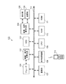
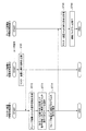
まず、本発明をHDDレコーダに適用した場合の実施の形態について説明する。図1は、本実施形態におけるHDDレコーダの構成を示したブロック図である。当該HDDレコーダ100は、AV機器として実装することができ、テレビジョン受信機(以下、単にテレビと記述する)と一体で構成することができる。
First, an embodiment when the present invention is applied to an HDD recorder will be described. FIG. 1 is a block diagram showing the configuration of the HDD recorder in the present embodiment. The
同図に示すように、HDDレコーダ100は、チューナ101、映像・音声符号化部102、HDD103、映像・音声復号化部104、表示部105、音響部106、通信部107、赤外線受信部108、CPU(Central Processing Unit)109、RAM(Random Access Memory)110及びROM(Read Only Memory)111から構成され、各部はバス112で接続されている。
As shown in the figure, the
チューナ101は、CPU109の制御に基づいて、衛星放送波、地上波等の所定チャンネルの放送波の選局を行い、受信したテレビ番組等のビデオコンテンツの映像信号及び音声信号を映像・音声符号化部102へ出力する。チューナ101の構成は、送信されてくる放送波がアナログであるかデジタルであるかに応じて適宜変更または拡張することができる。
The
映像・音声符号化部102は、チューナ101から出力された映像信号及び音声信号のうち、映像信号を例えばMPEG(Moving Picture Experts Group)−2圧縮符号化方式を用いて圧縮し、また音声信号を例えばドルビーデジタルAC−3(Audio Code number 3)等の圧縮方式を用いて符号化し、両者を多重化して圧縮ストリームを生成する。符号化されたデータはHDD103へ記録される。
The video /
HDD103は、上記符号化されたテレビ番組等の映像・音声データの他、各種プログラムやデータ等を蓄積することができる、ランダムアクセスが可能な外部記憶装置であり、例えば100GB以上の大容量を備えている。映像・音声復号化部104は、上記映像・音声データを再生する場合に、上記HDD103から当該データを入力し、映像信号と音声信号とにそれぞれ復号化した上で、映像信号を表示部105へ、また音声信号を音響部106へ出力する。
The
表示部105は例えばTFT(Thin Film Transistor)等のLCD(Liquid Crystal Display)、CRT(Cathode Ray Tube)、PDP(Plasma Display Panel)、OEL(Organic Electroluminescence)等からなり、上記映像信号を表示する。また上記音響部106は、図示しないアンプ及びスピーカ等からなり、上記音声信号を出力する。
The
通信部107は、インターネットに接続して例えばテレビ番組の予約の際に必要なEPG(Electronic Program Guide)データをダウンロードしたり、また他の機器と例えばLAN(Local Area Network)を介してデータの送受信を行ったりする。
The
赤外線受信部108は、リモートコントローラ(以下リモコンと記述する)113から送信される、各種制御命令またはリズムパターン情報としての赤外線信号を受信し、CPU109へ出力する。
The
CPU109は、HDDレコーダ100全体の動作を制御するメインコントローラであり、OS(Operating System)により提供されるプラットフォーム上で各種のアプリケーションを実行する。例えば、上記リモコン113により送信された赤外線信号のリズムパターンに基づいて、上記ビデオコンテンツの録画や再生等、対応する制御命令を実行する。
The
RAM110は、CPU109の実行プログラムをロードしたり、実行プログラムの作業データを書き込んだりするために用いられる、書き込み可能な揮発性のメモリである。またROM111は、HDDレコーダ100の電源オン時に実行するプログラムや、ハードウェア制御用の制御コードの他、上記リズムパターン情報を処理するためのデータ等を格納する、読み出し専用の不揮発性のメモリである。
The
また、リモコン113は、図示しないプッシュボタン等のユーザの操作により、HDDレコーダ100の所定の機能を実行させるための制御命令として、上記赤外線受信部108へ赤外線信号を送信する。また、上記各種制御命令に対応するリズムパターンを登録する際には、ユーザによる上記ボタンの一連の押下操作により、リズムパターンを構成する赤外線信号を上記赤外線受信部108へ送信する。
The
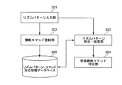
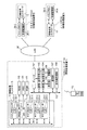
次に、本実施形態において、上記リズムパターン情報を処理するために必要なソフトウェア及びデータベースについて説明する。図2は、当該ソフトウェア及びデータベースの構成を示した図である。 Next, software and a database necessary for processing the rhythm pattern information in the present embodiment will be described. FIG. 2 is a diagram showing the configuration of the software and database.
同図に示すように、HDDレコーダ100は、リズムパターン入力部201、機能コマンド登録ソフトウェア部、リズムパターン照合・検索部203及び登録機能コマンド呼出部204の各ソフトウェア及びリズムパターン‐コマンド対応情報データベース205(以下、単に対応情報データベース205と記述する)を有する。
As shown in the figure, the
リズムパターン入力部201は、ユーザから上記リモコン113の押下操作により送信され上記赤外線受信部108により受信された複数回の一連の赤外線信号を検出し、当該信号をリズムパターンとして記録する。具体的には、上記赤外線受信部108から上記一連の赤外線信号を受け取り、当該信号をデジタルデータに変換して、各信号の入力イベントが発生した時刻及びその入力回数、入力に要した総時間のデータを一つのリズムパターンとして例えば上記RAM110に一時的に記録する。
The rhythm
機能コマンド登録部202は、上記リズムパターン入力部201により入力されたリズムパターンデータと、ユーザが指定した機能コマンドを対応付け、それらをリズムパターン‐コマンド対応情報データベース205に記録する。機能コマンドとは例えばHDDレコーダ100に録画してある所定のテレビ番組等のMPEG2動画コンテンツファイルを再生する等、HDDレコーダ100が有する具体的な機能を実行させるためのコマンドである。上記リズムパターンはユーザが任意に指定することができ、例えば上記機能コマンドにより再生される動画コンテンツのテーマ音楽のリズムを表したり、番組のタイトルや出演者名等をリズムで表したりするなど、上記機能コマンドから連想されるイメージをリズムパターンとして関連付けてもよい。
The function
リズムパターン照合・検索部203は、ユーザがHDDレコーダ100のある機能を実行させようと上記リモコン113から入力したリズムパターンを上記リズムパターン入力部201から受け取り、当該リズムパターンと一致するリズムパターンを上記対応情報データベース205から検索する。そして、当該検索の結果、一致または類似するリズムパターンを検出すると、当該リズムパターンに対応する機能コマンドを呼び出すため、登録機能コマンド呼出部204に要請する。
The rhythm pattern collation /
登録機能コマンド呼出部204は、上記リズムパターン照合・検索部203からの要請を受けて、当該機能コマンドを呼び出して実際に実行させる。
In response to the request from the rhythm pattern collation /
上記各ソフトウェア及び上記対応情報データベース205は上記HDD103に記憶され、必要に応じて上記RAM110へ呼び出されて実行及び参照される。
The software and the
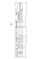
次に、上記対応情報データベース205の詳細について述べる。図3は、当該対応情報データベース205に格納されたデータを示した図である。
Next, details of the
同図に示すように、対応情報データベース205には、各リズムパターンを識別するためのリズムパターンID、リズムパターンを構成する各入力イベントの発生時刻、入力イベントの回数、入力に要した総入力時間及び当該リズムパターンに対応する機能コマンドの各データが格納されている。
As shown in the figure, the
入力イベント発生時刻は、最初に入力イベントが発生した時点を0として、その後の入力イベントが発生したタイミングを時刻(例えば秒単位)で表している。例えば、リズムパターンを「ト」または「トン」で表現するものとすると、同図においてリズムパターンIDが0001のリズムパターンは、入力イベント回数は4回で、1回目と2回目の各イベント間及び3回目と4回目の各イベント間の時間間隔が0.2秒で等しく、2回目と3回目の入力イベント間の時間間隔のみ0.4秒と2倍になっているため、「トトントトン」というリズムパターンを示している。またリズムパターンIDが0003のリズムパターンは、入力イベント回数が5回で、入力イベント発生時刻は1回目と2回目の間及び4回目と5回目の間の時間間隔が0.4秒で等しく、2回目と3回目の入力イベント間及び3回目と4回目の入力イベント間の時間間隔がその2倍の0.8秒であるため、「トトントントトン」というリズムパターンを示している。
The input event occurrence time is represented by time (for example, in seconds) when the first input event has occurred, and the subsequent input event has occurred. For example, if the rhythm pattern is expressed by “G” or “T”, the rhythm pattern with the
また、各リズムパターンに対応する機能コマンドは、上述したように、例えばHDDレコーダ100に記憶してある動画コンテンツを再生させる際には当該コンテンツを連想させるようなリズムを登録するようにしてもよい。より具体的には、当該動画コンテンツが映画のコンテンツであって、当該映画のテーマ音楽が例えば「ダダッダッダダン」というリズムであれば、当該リズムを連想させる上記「トトントントトン」というリズムパターンを登録するようにしてもよい。また、例えばサッカーのワールドカップ(登録商標)を録画した動画コンテンツであれば、「ワールドカップ」という言葉のリズムを連想させる「トントトトントン」というリズムパターンを登録するようにしてもよい。これにより、ユーザはコマンド毎にリズムパターンを記憶しておかなくても、当該コマンドを直感的に覚えておくことができる。
In addition, as described above, the function command corresponding to each rhythm pattern may register a rhythm reminiscent of the content when the moving image content stored in the
次に、以上のように構成されたHDDレコーダ100において、上記リズムパターンの入力により所定の機能が実行されるまでの動作を説明する。当該動作は、上記機能コマンドの登録と、当該登録された機能コマンドの呼び出しの2つの段階に分かれる。機能コマンドの登録動作においては、上記ソフトウェアのうち、リズムパターン入力部201及び機能コマンド登録部202が用いられ、機能コマンドの呼び出し動作においてはリズムパターン入力部201、リズムパターン照合・検索部203及び登録機能コマンド呼出部204が用いられる。
Next, in the
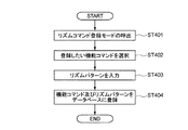
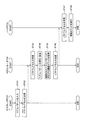
まず、機能コマンドを登録するまでの動作について説明する。図4は、当該動作の流れを示したフロー図である。同図においては、機能コマンドとして、所定の動画コンテンツの再生を実行させるコマンドを登録するものとする。 First, the operation until registering a function command will be described. FIG. 4 is a flowchart showing the flow of the operation. In the figure, it is assumed that a command for executing reproduction of a predetermined moving image content is registered as a function command.
同図に示すように、まず、ユーザがリモコン113を操作することにより、例えばHDDレコーダ100の表示部105またはリモコン113の図示しない液晶表示部に、「リズムコマンドの登録」といったメニュー画面を呼び出して、機能コマンドとリズムパターンの対応付けを登録するモードに入る(ステップ401)。続いて、記録済みの動画コンテンツの一覧画面を呼び出して、登録したい動画コンテンツを選択する(ステップ402)。
As shown in the figure, first, when the user operates the
次に、例えば「リズムコマンド登録を開始」といったボタンを押下した後、ユーザがリモコン113を複数回押下操作して赤外線信号を送信すると、上記赤外線受信部108及びリズムパターン入力部201が当該赤外線信号を検出して、当該信号のリズムパターンの時間間隔を示すための上記入力イベント発生時刻、入力イベント回数及び総入力時間をデジタルデータとして入力する(ステップ403)。
Next, for example, after the user presses a button such as “Start Rhythm Command Registration” and then presses the remote controller 113 a plurality of times to transmit an infrared signal, the
そして、上記機能コマンド登録部202が、当該入力されたリズムパターンと、上記選択した機能コマンド、すなわち『動画コンテンツ「○○○」の再生』というコマンドとを関連付けて、上記対応情報データベース205に記録する(ステップ404)ことにより、コマンド登録動作は終了する。
Then, the function
なお、上記対応情報データベース205には、入力イベント発生時刻を記録することにより、リズムパターンを、時間間隔をパラメータとして記録しているが、例えばユーザがボタンを押している時間長を示す情報も更にパラメータとして用いた、モールス信号のようなリズムパターン入力も可能である。また、入力信号のパワーも入力可能な入力デバイスを用いれば、ユーザの押圧力のようなパワーを示す値もパラメータとして用いて、リズムパターンを入力することも可能である。
In the
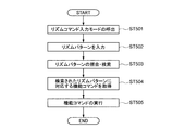
次に、上記登録した機能コマンドを呼び出して実行するまでの動作について説明する。図5は、当該動作の流れを示したフロー図である。 Next, the operation until the registered function command is called and executed will be described. FIG. 5 is a flowchart showing the flow of the operation.
同図に示すように、まず、ユーザがリモコン113を操作することにより、例えばリモコン113の図示しない液晶表示部に、「リズムコマンドの入力」といったメニュー画面を呼び出して、上記登録したリズムパターンの入力により機能コマンドを実行するモードに入る(ステップ501)。続いて、ユーザは当該モードにおいて、同じくリモコン113のボタンの押下操作により、上記登録したリズムパターンを入力する。なお、上記メニュー画面以外にも、例えば「リズムコマンド入力専用ボタン」のようなボタンを上記リモコン113に設けて、当該ボタンの押下操作によりリズムコマンドの入力を行ってもよい。
As shown in the figure, first, when the user operates the
次に、HDDレコーダ100のリズムパターン入力部201は、上記赤外線受信部108を介して当該リズムパターンを入力し(ステップ502)、上記入力イベント発生時刻等、当該リズムパターンを示すデータを上記リズムパターン照合・検索部203へ送信する。
Next, the rhythm
続いて、リズムパターン照合・検索部203は、リズムパターン入力部201から受信したリズムパターンと一致または類似するリズムパターンが上記対応情報データベース205に保存されているか否かを検索及び照合する(ステップ503)。この場合のリズムパターンの照合には、例えばDP(Dynamic Programming)マッチング(動的計画法)といった時間伸縮に対応した各種パターンマッチング手法を用いることができる。DPマッチングは、異なる要素数の物を比較する際、最小限の計算で比較するアルゴリズムで、音声認識、言語解析等に使用されている。
Subsequently, the rhythm pattern collation /
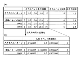
当該DPマッチングを用いたリズムパターンの具体的な照合処理について、図6を参照しながら説明する。同図は、入力されたリズムパターンと、当該リズムパターンの比較対象となる上記対応情報データベース205中のデータとの関係を示した図である。
A specific rhythm pattern matching process using the DP matching will be described with reference to FIG. The figure shows the relationship between the input rhythm pattern and the data in the
同図(a)は、上記ステップ502において入力されたリズムパターンと、上記対応情報データベース205に登録されている3つのリズムパターンの入力イベント発生時刻、入力イベント回数及び総入力時間を示している。上記リズムパターン照合・検索部203は、入力されたリズムパターンと同一と思われるリズムパターンを当該3つのパターンの中から検索することになる。まず入力イベント回数が異なるパターン0001は候補から外され、0002及び0003の2つのパターンから検索する。
FIG. 4A shows the rhythm pattern input in step 502 and the input event occurrence time, the number of input events, and the total input time of the three rhythm patterns registered in the
ところで、ユーザが毎回同じリズムパターンを入力する場合でも、その都度当該入力のテンポが速くなったり遅くなったりすることが考えられため、当該事情を考慮してパターンの照合を行う必要がある。そこで、リズムパターン照合・検索部203は、同図(b)に示すように、各リズムパターンの入力イベント発生時刻をそれぞれの総入力時間で正規化した上で両者を比較する。
By the way, even when the user inputs the same rhythm pattern every time, it is conceivable that the tempo of the input increases or decreases each time, and it is necessary to perform pattern matching in consideration of the circumstances. Therefore, the rhythm pattern collation /
すなわち、各リズムパターンの入力イベント発生時刻をそれぞれの総入力時間で除算して、それぞれについて総入力時間1秒当たりのテンポに換算して比較すると、パターン0002と0003はタイミングが明らかに異なっており、上記入力されたリズムパターンは、パターン0003と同一のパターンであることが分かる。なお、上記入力パターンの総入力時間は上記パターン0003の総入力時間の2分の1であるから、同図の場合、ユーザは登録時よりも2倍早いテンポで入力を行ったことを示している。また、ユーザが入力するリズムパターンは、テンポが同一でも、毎回厳密に同一の時間間隔で入力されるわけではなく、微妙なずれも生じることから、総入力時間で正規化した場合でも、全く同一パターンだけではなく、ほぼ同一に近い類似のパターンを該当パターンとして認識するようにしてもよい。
That is, when the input event occurrence time of each rhythm pattern is divided by the total input time and converted into a tempo per second for each total input time, the timings of
このように、総入力時間で各リズムパターンを正規化して比較することで、ユーザの入力テンポが登録された入力パターンと異なる場合でも同一または類似のパターンとして認識することができ、ユーザが意図せずに非類似のリズムパターンと判断されることを防ぐことができる。 In this way, by normalizing and comparing each rhythm pattern with the total input time, even if the input tempo of the user is different from the registered input pattern, it can be recognized as the same or similar pattern, and the user intends. Without being judged as a dissimilar rhythm pattern.
なお、リズムパターンの照合には、上記DPマッチング以外にも、例えば隠れマルコフモデル(HMM:Hidden Markov Model)等、様々な手法を用いることが可能である。一般に、ある事象の確率がその直前のN個の事象だけに依存するとき、これをN重マルコフ過程といい、隠れマルコフモデルは、「システムがパラメータ未知のマルコフ過程である」と仮定し、観測可能な情報からその未知のパラメータを推定する確率モデルの一つである。 In addition to the DP matching described above, various methods such as a hidden Markov model (HMM: Hidden Markov Model) can be used for rhythm pattern matching. In general, when the probability of an event depends only on the N events just before it, this is called an N-fold Markov process, and the hidden Markov model assumes that the system is a Markov process with unknown parameters. It is one of the probabilistic models that estimate the unknown parameters from possible information.
以上のような照合・検索手法により、入力されたリズムパターンと同一または類似のリズムパターンを抽出すると、リズムパターン照合・検索部203は、上記対応情報データベース205を参照して、抽出したリズムパターンに対応付けられた機能コマンドを取得する(ステップ504)。例えば、ユーザにより「トトントントトン」というリズムパターンが正しく入力された場合には、当該リズムパターンに対応する『動画コンテンツ「○○○」の再生』というコマンドを取得する。
When a rhythm pattern that is the same as or similar to the input rhythm pattern is extracted by the above collation / retrieval method, the rhythm pattern collation /
そして、リズムパターン照合・検索部203が、上記当該取得したコマンドを上記登録機能コマンド呼出部204へ送信して実行させることにより、ユーザが上記リズムパターンの入力により所望した上記動画コンテンツの再生という動作が実行される(ステップ505)。
Then, the rhythm pattern matching / searching
以上のコマンド登録及びコマンド呼出の動作により、従来ならば例えばメニュー画面から項目を選択するといった何段階かの複雑な操作や複数の操作が必要であった機能を、ユーザはリズムパターンの入力という単純で分かりやすいインターフェースにより、容易に実行させることができる。 With the above-described command registration and command call operations, a function that conventionally required several steps of complicated operations such as selecting an item from a menu screen or a plurality of operations can be simply performed by the user by inputting a rhythm pattern. With an easy-to-understand interface, it can be easily executed.
またユーザは、上記機能コマンドを、当該機能コマンドに対するユーザのイメージをリズムパターンとして結びつけて登録させておくことができるため、当該結びつきを直感的に記憶し、または思い出すことができ、わざわざ記憶したりその操作に慣れたりする等しなくとも、容易に操作を行うことができる。 In addition, since the user can register the function command by linking the user's image to the function command as a rhythm pattern, the user can memorize or remember the connection intuitively. Even without getting used to the operation, the operation can be easily performed.
更に、例えばプッシュボタンしか有さないリモコン113のような単純な入力デバイスであっても、複雑な機能を上記リズムパターンと関連付けて登録し、かつ当該機能を瞬時に呼び出し、実行することができる。
Further, even a simple input device such as the
なお、本発明は以上説明した実施の形態には限定されるものではなく、種々の変形が可能である。 The present invention is not limited to the embodiments described above, and various modifications can be made.
上述の実施形態においては、本発明をHDDレコーダ100に適用して、所望の動画コンテンツを再生するという操作を実行させる例について説明したが、それ以外にも、例えばオーディオプレーヤや携帯電話等、何らかの入力デバイスが存在する機器であればどのような機器にも適用することができる。
In the above-described embodiment, an example in which the present invention is applied to the
オーディオプレーヤに適用した場合には、所望の曲を再生させる場合に、曲を呼び出して再生モードにし、再生ボタンを押すというような処理を、例えば曲の代表的なフレーズやアーティスト名をリズムパターンとして登録しておけば、当該リズムパターンの入力により所望の曲を瞬時に再生させることが可能である。 When applied to an audio player, when a desired song is played, a process such as calling the song and setting the playback mode and pressing the play button is performed, for example, using a typical phrase or artist name of the song as a rhythm pattern. If registered, a desired tune can be instantaneously reproduced by inputting the rhythm pattern.
携帯電話に適用した場合には、例えば電子メール機能付きの携帯電話においては、メール文書作成においてよく使う「いってらっしゃーい」のような文字列に対して、これを発音した時のリズムを「トットトントーン」のようなリズムパターンとして登録しておき、ボタン一つで瞬時に文章入力を行うようにしてもよい。これにより、携帯電話のような文字入力手段が限られている機器においても容易に文字入力を行うことができる。 When applied to a mobile phone, for example, on a mobile phone with an e-mail function, the rhythm when it is pronounced for a character string such as “Iterasesai” that is often used in mail document creation is used. It may be registered as a rhythm pattern such as “Totton tone”, and text may be input instantaneously with a single button. Thereby, it is possible to easily input characters even in a device such as a mobile phone that has limited character input means.
また、相手に電話をかける場合に、所望の電話番号を呼び出してダイヤルするまでの操作について、例えばその相手から連想されるイメージをリズムパターンと関連付けて登録しておくことも可能である。これにより、従来の短縮コマンドのような機能に比べて、登録した短縮コマンドの番号をいちいち覚えておく必要がないため、多くの人についてリズムパターンを登録した場合でも、単純なリズム入力で各人に容易に電話をかけることが可能となる。 Further, when making a call to the other party, for example, an operation associated with calling a desired telephone number and dialing it can be registered in association with an rhythm pattern. This eliminates the need to remember the number of registered abbreviated commands each time compared to functions like conventional abbreviated commands, so even if you register rhythm patterns for many people, It is possible to make a call easily.
上述の実施形態においてはリモコン113を入力デバイスとして用いていたが、マウス、キーボード、ジョグダイヤル等、様々な入力デバイスを用いることができる。キーボードの場合には、例えばキーボードのいくつかのキーをピアノの鍵盤に見立てて、ある旋律をリズムパターンとして登録しておくことも可能である。更に、カメラ及び撮像した画像の画像認識機能を有する機器であれば、例えばユーザがカメラの前で所定の方向に手を振る等の動作を画像認識させて機能コマンドと対応付けて登録しておき、ユーザが再度手を振った場合に当該機能を実行させるような態様も可能である。
In the above-described embodiment, the
また、本発明においてはユーザの感情を上記リズムパターンと関連付けることもできるため、例えばPCのディスプレイにおいて、予め明るい気分を連想させるようなリズムパターンを明るい感じのデザインのデスクトップテーマに関連付けて登録しておき、後に当該リズムパターンを入力することによってテーマの変更を行ったりすることも可能である。 In the present invention, since the user's emotion can be associated with the rhythm pattern, for example, on a PC display, a rhythm pattern reminiscent of a bright mood is registered in association with a desktop theme with a bright feeling design. It is also possible to change the theme by inputting the rhythm pattern later.
更に、本発明を以下の実施形態において説明するようなネットワークシステムに適用することも可能である。
(第2の実施形態)
Furthermore, the present invention can be applied to a network system as described in the following embodiments.
(Second Embodiment)
まず、本実施形態において前提となるネットワークシステムについて説明する。 First, a network system that is a premise in the present embodiment will be described.
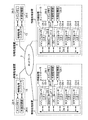
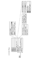
図7は、この発明のネットワークシステムの一例を示し、ネットワーク9を介して複数の情報処理装置1、2、3、4が接続されたものである。情報処理装置1、2、3、4は、例えば各種のAV機器やポータブル機器、後述するHDDレコーダ、PC等である。
FIG. 7 shows an example of a network system according to the present invention, in which a plurality of
情報処理装置1について示すと、情報処理装置1は、コンピュータ機能部として情報処理コントローラ11を備える。情報処理コントローラ11は、メインプロセッサ21−1、サブプロセッサ23−1、23−2、23−3、DMAC(ダイレクトメモリアクセスコントローラ)25−1及びDC(ディスクコントローラ)27−1を有する。
As for the
メインプロセッサ21−1は、サブプロセッサ23−1、23−2、23−3によるプログラム実行(データ処理)のスケジュール管理と、情報処理コントローラ11(情報処理装置1)の全般的な管理とを行う。ただし、メインプロセッサ21−1内で管理のためのプログラム以外のプログラムが動作するように構成することもできる。その場合には、メインプロセッサ21−1はサブプロセッサとしても機能することになる。メインプロセッサ21−1は、LS(ローカルストレージ)22−1を有する。 The main processor 21-1 performs schedule management of program execution (data processing) by the sub processors 23-1, 23-2, and 23-3, and general management of the information processing controller 11 (information processing apparatus 1). . However, a program other than the management program may be operated in the main processor 21-1. In that case, the main processor 21-1 also functions as a sub processor. The main processor 21-1 has an LS (local storage) 22-1.
サブプロセッサは、1つでもよいが、望ましくは複数とする。本例は、複数の場合である。各サブプロセッサ23−1、23−2、23−3は、メインプロセッサ21−1の制御によって並列的かつ独立にプログラムを実行し、データを処理する。更に、場合によってメインプロセッサ21−1内のプログラムがサブプロセッサ23−1、23−2、23−3内のプログラムと連携して動作するように構成することもできる。後述する機能プログラムもメインプロセッサ21−1内で動作するプログラムである。各サブプロセッサ23−1、23−2、23−3も、LS(ローカルストレージ)24−1、24−2、24−3を有する。 There may be one sub-processor, but preferably there are a plurality of sub-processors. This example is a plurality of cases. Each sub-processor 23-1, 23-2, 23-3 executes a program in parallel and independently under the control of the main processor 21-1, and processes data. Further, in some cases, the program in the main processor 21-1 can be configured to operate in cooperation with the programs in the sub processors 23-1, 23-2, and 23-3. A function program described later is also a program that operates in the main processor 21-1. Each of the sub-processors 23-1, 23-2, 23-3 also has LS (local storage) 24-1, 24-2, 24-3.
DMAC25−1は、情報処理コントローラ11に接続されたDRAM(ダイナミックRAM)などからなるメインメモリ26−1に格納されているプログラム及びデータにアクセスするものであり、DC27−1は、情報処理コントローラ11に接続された外部記録部28−1、28−2にアクセスするものである。
The DMAC 25-1 accesses a program and data stored in a main memory 26-1 including a DRAM (dynamic RAM) connected to the
外部記録部28−1、28−2は、固定ディスク(ハードディスク)でも、リムーバブルディスクでもよく、また、MO、CD±RW、DVD±RWなどの光ディスク、メモリディスク、SRAM(スタティックRAM)、ROMなど、各種のものを用いることができる。したがって、DC27−1は、ディスクコントローラと称するが、外部記録部コントローラである。図7の例のように、情報処理コントローラ11に対して外部記録部28を複数接続できるように、情報処理コントローラ11を構成することができる。
The external recording units 28-1 and 28-2 may be fixed disks (hard disks) or removable disks, and are optical disks such as MO, CD ± RW, DVD ± RW, memory disks, SRAM (static RAM), ROM, etc. Various types can be used. Therefore, although DC27-1 is called a disk controller, it is an external recording unit controller. As in the example of FIG. 7, the
メインプロセッサ21−1、各サブプロセッサ23−1、23−2、23−3、DMAC25−1及びDC27−1は、バス29−1によって接続される。 The main processor 21-1, the sub processors 23-1, 23-2, 23-3, the DMAC 25-1, and the DC 27-1 are connected by a bus 29-1.
情報処理コントローラ11には、当該の情報処理コントローラ11を備える情報処理装置1を、ネットワーク全体を通して一意的に識別できる識別子が、情報処理装置IDとして割り当てられる。
An identifier that can uniquely identify the
メインプロセッサ21−1及び各サブプロセッサ23−1、23−2、23−3に対しても同様に、それぞれを特定できる識別子が、メインプロセッサID及びサブプロセッサIDとして割り当てられる。 Similarly, identifiers that can identify the main processor 21-1 and the sub processors 23-1, 23-2, and 23-3 are assigned as the main processor ID and the sub processor ID.
情報処理コントローラ11は、ワンチップIC(集積回路)として構成することが望ましい。他の情報処理装置2、3、4も、上記と同様に構成される。ここで、図7において親番号が同一であるユニットは枝番号が異なっていても、特に断りがない限り同じ働きをするものとする。また、以下の説明において枝番号が省略されている場合には、枝番号の違いにいる差異を生じないものとする。
The
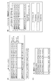
上述したように、1つの情報処理コントローラ内の各サブプロセッサ23は、独立にプログラムを実行し、データを処理するが、異なるサブプロセッサがメインメモリ26内の同一領域に対して同時に読み出しまたは書き込みを行った場合には、データの不整合を生じ得る。そこで、サブプロセッサ23からメインメモリ26へのアクセスは、以下のような手順によって行う。 As described above, each sub-processor 23 in one information processing controller independently executes a program and processes data, but different sub-processors simultaneously read or write to the same area in the main memory 26. If done, data inconsistencies can occur. Therefore, access from the sub processor 23 to the main memory 26 is performed according to the following procedure.
図8(A)に示すように、メインメモリ26は、複数のアドレスを指定できるメモリロケーションによって構成される。各メモリロケーションに対しては、データの状態を示す情報を格納するための追加セグメントが割り振られる。追加セグメントは、F/Eビット、サブプロセッサID及びLSアドレス(ローカルストレージアドレス)を含むものとされる。また、各メモリロケーションには、後述のアクセスキーも割り振られる。F/Eビットは、以下のように定義される。 As shown in FIG. 8A, the main memory 26 is composed of memory locations that can specify a plurality of addresses. Each memory location is allocated an additional segment for storing information indicating the state of the data. The additional segment includes an F / E bit, a sub processor ID, and an LS address (local storage address). Each memory location is also assigned an access key to be described later. The F / E bit is defined as follows.
F/Eビット=0は、サブプロセッサ23によって読み出されている処理中のデータ、または空き状態であるため最新データではない無効データであり、読み出し不可であることを示す。また、F/Eビット=0は、当該メモリロケーションにデータ書き込み可能であることを示し、書き込み後に1に設定される。 The F / E bit = 0 indicates that the data being processed being read by the sub-processor 23 or invalid data that is not the latest data because it is empty and cannot be read. The F / E bit = 0 indicates that data can be written to the memory location, and is set to 1 after writing.
F/Eビット=1は、当該メモリロケーションのデータがサブプロセッサ23によって読み出されておらず、未処理の最新データであることを示す。当該メモリロケーションのデータは読み出し可能であり、サブプロセッサ23によって読み出された後に0に設定される。また、F/Eビット=1は、当該メモリロケーションがデータ書き込み不可であることを示す。 The F / E bit = 1 indicates that the data at the memory location has not been read by the sub-processor 23 and is the latest unprocessed data. The data in the memory location can be read and set to 0 after being read by the sub-processor 23. Further, the F / E bit = 1 indicates that the memory location cannot write data.
更に、上記F/Eビット=0(読み出し不可/書き込み可)の状態において、当該メモリロケーションについて読み出し予約を設定することは可能である。F/Eビット=0のメモリロケーションに対して読み出し予約を行う場合には、サブプロセッサ23は、読み出し予約を行うメモリロケーションの追加セグメントに、読み出し予約情報として当該サブプロセッサ23のサブプロセッサID及びLSアドレスを書き込む。 Furthermore, it is possible to set a read reservation for the memory location in the state where the F / E bit = 0 (reading impossible / writing possible). When a read reservation is made for a memory location with the F / E bit = 0, the sub processor 23 adds the sub processor ID and LS of the sub processor 23 as read reservation information to an additional segment of the memory location where the read reservation is made. Write the address.
その後、データ書き込み側のサブプロセッサ23によって、読み出し予約されたメモリロケーションにデータが書き込まれ、F/Eビット=1(読み出し可/書き込み不可)に設定されたとき、予め読み出し予約情報として追加セグメントに書き込まれたサブプロセッサID及びLSアドレスに読み出される。 Thereafter, when data is written to the memory location reserved for reading by the sub-processor 23 on the data writing side and the F / E bit is set to 1 (readable / not writable), it is preliminarily stored in the additional segment as read reservation information. Read to the written sub-processor ID and LS address.
複数のサブプロセッサによってデータを多段階に処理する必要がある場合、このように各メモリロケーションのデータの読み出し/書き込みを制御することによって、前段階の処理を行うサブプロセッサ23が、処理済みのデータをメインメモリ26上の所定のアドレスに書き込んだ後に即座に、後段階の処理を行う別のサブプロセッサ23が前処理後のデータを読み出すことが可能となる。 When it is necessary to process data in multiple stages by a plurality of sub-processors, the sub-processor 23 that performs the process in the previous stage controls the read / write of the data in each memory location in this way. Immediately after the data is written at a predetermined address on the main memory 26, another sub-processor 23 that performs the subsequent processing can read the data after the preprocessing.
図8(B)に示すように、各サブプロセッサ23内のLS24も、複数のアドレスを指定できるメモリロケーションによって構成される。各メモリロケーションに対しては、同様に追加セグメントが割り振られる。追加セグメントは、ビジービットを含むものとされる。 As shown in FIG. 8B, the LS 24 in each sub-processor 23 is also configured by memory locations that can specify a plurality of addresses. An additional segment is similarly allocated for each memory location. The additional segment includes a busy bit.
サブプロセッサ23がメインメモリ26内のデータを自身のLS24のメモリロケーションに読み出すときには、対応するビジービットを1に設定して予約する。ビジービットが1であるメモリロケーションには、他のデータは格納することができない。LS24のメモリロケーションに読み出し後、ビジービットは0になり、任意の目的に使用できるようになる。 When the sub-processor 23 reads the data in the main memory 26 to the memory location of its own LS 24, it reserves by setting the corresponding busy bit to 1. No other data can be stored in the memory location where the busy bit is 1. After reading to the memory location of the LS 24, the busy bit becomes 0 and can be used for any purpose.
図8(A)に示すように、さらに、各情報処理コントローラと接続されたメインメモリ26には、複数のサンドボックスが含まれる。サンドボックスは、メインメモリ26内の領域を画定するものであり、各サンドボックスは、各サブプロセッサ23に割り当てられ、そのサブプロセッサが排他的に使用することができる。すなわち、各々のサブプロセッサ23は、自身に割り当てられたサンドボックスを使用できるが、この領域を超えてデータのアクセスを行うことはできない。メインメモリ26は、複数のメモリロケーションから構成されるが、サンドボックスは、これらのメモリロケーションの集合である。 As shown in FIG. 8A, the main memory 26 connected to each information processing controller further includes a plurality of sandboxes. The sandbox defines an area in the main memory 26, and each sandbox is assigned to each sub processor 23 and can be used exclusively by the sub processor. That is, each sub-processor 23 can use a sandbox assigned to itself, but cannot access data beyond this area. The main memory 26 is composed of a plurality of memory locations, and the sandbox is a set of these memory locations.
更に、メインメモリ26の排他的な制御を実現するために、図8(C)に示すようなキー管理テーブルが用いられる。キー管理テーブルは、情報処理コントローラ内のSRAM等の比較的高速のメモリに格納され、DMAC25と関連付けられる。キー管理テーブル内の各エントリには、サブプロセッサID、サブプロセッサキー及びキーマスクが含まれる。 Furthermore, in order to realize exclusive control of the main memory 26, a key management table as shown in FIG. 8C is used. The key management table is stored in a relatively high-speed memory such as SRAM in the information processing controller, and is associated with the DMAC 25. Each entry in the key management table includes a sub processor ID, a sub processor key, and a key mask.
サブプロセッサ23がメインメモリ26を使用する際のプロセスは、以下の通りである。まず、サブプロセッサ23はDMAC25に、読み出しまたは書き込みのコマンドを出力する。このコマンドには、自身のサブプロセッサIDと、使用要求先であるメインメモリ26のアドレスが含まれる。 The process when the sub processor 23 uses the main memory 26 is as follows. First, the sub processor 23 outputs a read or write command to the DMAC 25. This command includes its own sub-processor ID and the address of the main memory 26 that is the use request destination.
DMAC25は、このコマンドを実行する前に、キー管理テーブルを参照して、使用要求元のサブプロセッサのサブプロセッサキーを調べる。次に、DMAC25は、調べた使用要求元のサブプロセッサキーと、使用要求先であるメインメモリ26内の図8(A)に示したメモリロケーションに割り振られたアクセスキーとを比較して、2つのキーが一致した場合にのみ、上記のコマンドを実行する。 Before executing this command, the DMAC 25 refers to the key management table and checks the sub processor key of the sub processor of the use request source. Next, the DMAC 25 compares the examined sub-processor key of the use request source with the access key allocated to the memory location shown in FIG. Execute the above command only when two keys match.
図8(C)に示したキー管理テーブル上のキーマスクは、その任意のビットが1になることによって、そのキーマスクに関連付けられたサブプロセッサキーの対応するビットが0または1になることができる。例えば、サブプロセッサキーが1010であるとする。通常、このサブプロセッサキーによって1010のアクセスキーを持つサンドボックスへのアクセスだけが可能になる。しかし、このサブプロセッサキーと関連付けられたキーマスクが0001に設定されている場合には、キーマスクのビットが1に設定された桁のみにつき、サブプロセッサキーとアクセスキーとの一致判定がマスクされ、このサブプロセッサキー1010によってアクセスキーが1010または1011のいずれかであるアクセスキーを持つサンドボックスへのアクセスが可能となる。 In the key mask on the key management table shown in FIG. 8C, when the arbitrary bit becomes 1, the corresponding bit of the sub processor key associated with the key mask may become 0 or 1. it can. For example, assume that the sub-processor key is 1010. Normally, this sub-processor key only allows access to a sandbox with 1010 access keys. However, if the key mask associated with this sub-processor key is set to 0001, the match determination between the sub-processor key and the access key is masked only for the digit whose key mask bit is set to 1. This sub-processor key 1010 enables access to a sandbox having an access key whose access key is either 1010 or 1011.
以上のようにして、メインメモリ26のサンドボックスの排他性が実現される。すなわち、1つの情報処理コントローラ内の複数のサブプロセッサによってデータを多段階に処理する必要がある場合、以上のように構成することによって、前段階の処理を行うサブプロセッサと、後段階の処理を行うサブプロセッサのみが、メインメモリ26の所定アドレスにアクセスできるようになり、データを保護することができる。 As described above, the sandbox exclusivity of the main memory 26 is realized. That is, when it is necessary to process data in multiple stages by a plurality of sub-processors in one information processing controller, by configuring as described above, the sub-processor that performs the process in the previous stage and the process in the subsequent stage are processed. Only the sub processor that performs the access can access a predetermined address in the main memory 26, and data can be protected.
例えば、以下のように使用することが考えられる。まず、情報処理装置の起動直後においては、キーマスクの値は全てゼロである。メインプロセッサ内のプログラムが実行され、サブプロセッサ内のプログラムと連携動作するものとする。第1のサブプロセッサにより出力された処理結果データを一旦メインメモリに格納し、第2のサブプロセッサに入力したいときには、該当するメインメモリ領域は、当然どちらのサブプロセッサからもアクセス可能である必要がある。そのような場合に、メインプロセッサ内のプログラムは、キーマスクの値を適切に変更し、複数のサブプロセッサからアクセスできるメインメモリ領域を設けることにより、サブプロセッサによる多段階的な処理を可能にする。 For example, it can be used as follows. First, immediately after the information processing apparatus is activated, the values of the key masks are all zero. It is assumed that a program in the main processor is executed and operates in cooperation with a program in the sub processor. When the processing result data output by the first sub-processor is temporarily stored in the main memory and desired to be input to the second sub-processor, the corresponding main memory area must naturally be accessible from either sub-processor. is there. In such a case, the program in the main processor appropriately changes the value of the key mask and provides a main memory area that can be accessed from a plurality of sub processors, thereby enabling multi-stage processing by the sub processors. .
より具体的には、他の情報処理装置からのデータ→第1のサブプロセッサによる処理→第1のメインメモリ領域→第2のサブプロセッサによる処理→第2のメインメモリ領域、という手順で多段階処理が行われるときには、 More specifically, it is a multi-step process in the order of data from another information processing apparatus → processing by the first sub processor → first main memory area → processing by the second sub processor → second main memory area. When processing is done,
第1のサブプロセッサのサブプロセッサキー:0100、 Sub-processor key of the first sub-processor: 0100
第1のメインメモリ領域のアクセスキー :0100、 First main memory area access key: 0100,
第2のサブプロセッサのサブプロセッサキー:0101、 Sub-processor key of the second sub-processor: 0101,
第2のメインメモリ領域のアクセスキー :0101
というような設定のままだと、第2のサブプロセッサは第1のメインメモリ領域にアクセスすることができない。そこで、第2のサブプロセッサのキーマスクを0001にすることにより、第2のサブプロセッサによる第1のメインメモリ領域へのアクセスを可能にすることができる。
Access key for second main memory area: 0101
In such a setting, the second sub-processor cannot access the first main memory area. Therefore, by setting the key mask of the second sub processor to 0001, it is possible to allow the second sub processor to access the first main memory area.
図7のネットワークシステムでは、情報処理装置1、2、3、4間での分散処理のために、情報処理装置1、2、3、4間でソフトウェアセルが伝送される。すなわち、ある情報処理装置内の情報処理コントローラに含まれるメインプロセッサ21は、コマンド、プログラム及びデータを含むソフトウェアセルを生成し、ネットワーク9を介して他の情報処理装置に送信することによって、処理を分散することができる。
In the network system of FIG. 7, software cells are transmitted between the
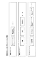
図9に、ソフトウェアセルの構成の一例を示す。この例のソフトウェアセルは、全体として、送信元ID、送信先ID、応答先ID、セルインターフェース、DMAコマンド、プログラム及びデータによって構成される。 FIG. 9 shows an example of the configuration of the software cell. The software cell in this example is composed of a transmission source ID, a transmission destination ID, a response destination ID, a cell interface, a DMA command, a program, and data as a whole.
送信元IDには、ソフトウェアセルの送信元である情報処理装置のネットワークアドレス及び当該情報処理装置の情報処理装置ID、更に、その情報処理装置内の情報処理コントローラが備えるメインプロセッサ21及び各サブプロセッサ23の識別子(メインプロセッサID及びサブプロセッサID)が含まれる。 The transmission source ID includes the network address of the information processing apparatus that is the transmission source of the software cell, the information processing apparatus ID of the information processing apparatus, and the main processor 21 and each sub processor included in the information processing controller in the information processing apparatus. 23 identifiers (main processor ID and sub-processor ID) are included.
送信先ID及び応答先IDには、それぞれ、ソフトウェアセルの送信先である情報処理装置、及びソフトウェアセルの実行結果の応答先である情報処理装置についての、同じ情報が含まれる。 The transmission destination ID and the response destination ID include the same information about the information processing apparatus that is the transmission destination of the software cell and the information processing apparatus that is the response destination of the execution result of the software cell, respectively.
セルインターフェースは、ソフトウェアセルの利用に必要な情報であり、グローバルID、必要なサブプロセッサの情報、サンドボックスサイズ及び前回のソフトウェアセルIDから構成される。 The cell interface is information necessary for using the software cell, and includes a global ID, necessary sub-processor information, a sandbox size, and a previous software cell ID.
グローバルIDは、ネットワーク全体を通して当該ソフトウェアセルを一意的に識別できるものであり、送信元ID及びソフトウェアセルの作成または送信の日時(日付及び時刻)に基づいて作成される。 The global ID can uniquely identify the software cell throughout the network, and is created based on the transmission source ID and the date and time (date and time) of creation or transmission of the software cell.
必要なサブプロセッサの情報は、当該ソフトウェアセルの実行に必要なサブプロセッサの数を設定する。サンドボックスサイズは、当該ソフトウェアセルの実行に必要なメインメモリ26内及びサブプロセッサ23のLS24内のメモリ量を設定する。前回のソフトウェアセルIDは、ストリーミングデータなどのシーケンシャルな実行を要求する1グループのソフトウェアセル内の、前回のソフトウェアセルの識別子である。 The necessary sub-processor information sets the number of sub-processors necessary for executing the software cell. The sandbox size sets the amount of memory in the main memory 26 and the LS 24 of the sub processor 23 necessary for executing the software cell. The previous software cell ID is an identifier of the previous software cell in a group of software cells that request sequential execution of streaming data or the like.
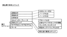
ソフトウェアセルの実行セクションは、DMAコマンド、プログラム及びデータから構成される。DMAコマンドには、プログラムの起動に必要な一連のDMAコマンドが含まれ、プログラムには、サブプロセッサ23によって実行されるサブプロセッサプログラムが含まれる。ここでのデータは、このサブプロセッサプログラムを含むプログラムによって処理されるデータである。 The execution section of the software cell is composed of DMA commands, programs, and data. The DMA command includes a series of DMA commands necessary for starting the program, and the program includes a sub processor program executed by the sub processor 23. The data here is data processed by a program including the sub processor program.
更に、DMAコマンドには、ロードコマンド、キックコマンド、機能プログラム実行コマンド、ステータス要求コマンド、及びステータス返信コマンドが含まれる。 Further, the DMA command includes a load command, a kick command, a function program execution command, a status request command, and a status return command.
ロードコマンドは、メインメモリ26内の情報をサブプロセッサ23内のLS24にロードするコマンドであり、ロードコマンド自体のほかに、メインメモリアドレス、サブプロセッサID及びLSアドレスを含む。メインメモリアドレスは、情報のロード元であるメインメモリ26内の所定領域のアドレスを示す。サブプロセッサID及びLSアドレスは、情報のロード先であるサブプロセッサ23の識別子及びLS24のアドレスを示す。 The load command is a command for loading information in the main memory 26 into the LS 24 in the sub processor 23, and includes a main memory address, a sub processor ID, and an LS address in addition to the load command itself. The main memory address indicates an address of a predetermined area in the main memory 26 from which information is loaded. The sub processor ID and the LS address indicate the identifier of the sub processor 23 to which the information is loaded and the address of the LS 24.
キックコマンドは、プログラムの実行を開始するコマンドであり、キックコマンド自体のほかに、サブプロセッサID及びプログラムカウンタを含む。サブプロセッサIDは、キック対象のサブプロセッサ23を識別し、プログラムカウンタは、プログラム実行用プログラムカウンタのためのアドレスを与える。 The kick command is a command for starting execution of a program, and includes a sub processor ID and a program counter in addition to the kick command itself. The sub processor ID identifies the sub processor 23 to be kicked, and the program counter gives an address for the program execution program counter.
機能プログラム実行コマンドは、後述のように、ある情報処理装置が他の情報処理装置に対して、機能プログラムの実行を要求するコマンドである。機能プログラム実行コマンドを受信した情報処理装置内の情報処理コントローラは、後述の機能プログラムIDによって、起動すべき機能プログラムを識別する。 As will be described later, the function program execution command is a command for requesting execution of a function program from another information processing apparatus to another information processing apparatus. The information processing controller in the information processing apparatus that has received the function program execution command identifies a function program to be activated by a function program ID described later.
ステータス要求コマンドは、送信先IDで示される情報処理装置の現在の動作状態(状況)に関する装置情報を、応答先IDで示される情報処理装置宛に送信要求するコマンドである。機能プログラムについては後述するが、図12に示す情報処理コントローラのメインメモリ26が記憶するソフトウェアの構成図において機能プログラムにカテゴライズされるプログラムである。機能プログラムは、メインメモリ26にロードされ、メインプロセッサ21により実行される。 The status request command is a command for requesting transmission of device information related to the current operation state (situation) of the information processing device indicated by the transmission destination ID to the information processing device indicated by the response destination ID. Although the function program will be described later, it is a program categorized into the function program in the software configuration diagram stored in the main memory 26 of the information processing controller shown in FIG. The function program is loaded into the main memory 26 and executed by the main processor 21.
ステータス返信コマンドは、上記のステータス要求コマンドを受信した情報処理装置が、自身の装置情報を当該ステータス要求コマンドに含まれる応答先IDで示される情報処理装置に応答するコマンドである。ステータス返信コマンドは、実行セクションのデータ領域に装置情報を格納する。 The status reply command is a command in which the information processing apparatus that has received the status request command responds to the information processing apparatus indicated by the response destination ID included in the status request command with its own apparatus information. The status reply command stores device information in the data area of the execution section.
図10に、DMAコマンドがステータス返信コマンドである場合におけるソフトウェアセルのデータ領域の構造を示す。 FIG. 10 shows the structure of the data area of the software cell when the DMA command is a status return command.
情報処理装置IDは、情報処理コントローラを備える情報処理装置を識別するための識別子であり、ステータス返信コマンドを送信する情報処理装置のIDを示す。情報処理装置IDは、電源投入時、その情報処理装置内の情報処理コントローラに含まれるメインプロセッサ21によって、電源投入時の日時、情報処理装置のネットワークアドレス及び情報処理装置内の情報処理コントローラに含まれるサブプロセッサ23の数などに基づいて生成される。 The information processing device ID is an identifier for identifying the information processing device including the information processing controller, and indicates the ID of the information processing device that transmits the status reply command. The information processing device ID is included in the information processing controller in the information processing device by the main processor 21 included in the information processing controller in the information processing device when the power is turned on. It is generated based on the number of sub processors 23 to be processed.
情報処理装置種別IDには、当該情報処理装置の特徴を表す値が含まれる。情報処理装置の特徴とは、例えば、オーディオプレーヤや後述のHDDレコーダ等である。また、情報処理装置種別IDは、音声情報再生、映像記録再生等の機能を表すものであってもよい。情報処理装置の特徴や機能を表す値は予め決定されているものとし、情報処理装置種別IDを読み出すことにより、当該情報処理装置の特徴や機能を把握することが可能である。 The information processing device type ID includes a value representing the characteristics of the information processing device. The characteristics of the information processing apparatus are, for example, an audio player, an HDD recorder described later, and the like. Further, the information processing apparatus type ID may represent functions such as audio information reproduction and video recording / reproduction. It is assumed that values representing the characteristics and functions of the information processing apparatus are determined in advance, and it is possible to grasp the characteristics and functions of the information processing apparatus by reading the information processing apparatus type ID.
MS(マスター/スレーブ)ステータスは、後述のように情報処理装置がマスター装置またはスレーブ装置のいずれで動作しているかを表すもので、これが0に設定されている場合にはマスター装置として動作していることを示し、1に設定されている場合にはスレーブ装置として動作していることを示す。 The MS (master / slave) status indicates whether the information processing apparatus is operating as a master apparatus or a slave apparatus, as will be described later. When this is set to 0, it operates as a master apparatus. If it is set to 1, it indicates that it is operating as a slave device.
メインプロセッサ動作周波数は、情報処理コントローラ内のメインプロセッサ21の動作周波数を表す。メインプロセッサ使用率は、メインプロセッサ21で現在動作している全てのプログラムについての、メインプロセッサ21での使用率を表す。メインプロセッサ使用率は、対象メインプロセッサの全処理能力に対する使用中の処理能力の比率を表した値で、例えばプロセッサ処理能力評価のための単位であるMIPSを単位として算出され、または単位時間あたりのプロセッサ使用時間に基づいて算出される。後述のサブプロセッサ使用率についても同様である。 The main processor operating frequency represents the operating frequency of the main processor 21 in the information processing controller. The main processor usage rate represents the usage rate in the main processor 21 for all programs currently running on the main processor 21. The main processor usage rate is a value representing the ratio of the processing capacity in use to the total processing capacity of the target main processor. For example, the main processor usage rate is calculated by using MIPS, which is a unit for evaluating the processor processing capacity, or per unit time. Calculated based on processor usage time. The same applies to the sub-processor usage rate described later.
サブプロセッサ数は、当該の情報処理コントローラが備えるサブプロセッサ23の数を表す。サブプロセッサIDは、当該の情報処理コントローラ内の各サブプロセッサ23を識別するための識別子である。 The number of sub-processors represents the number of sub-processors 23 included in the information processing controller. The sub processor ID is an identifier for identifying each sub processor 23 in the information processing controller.
サブプロセッサステータスは、各サブプロセッサ23の状態を表すものであり、unused、reserved、busyなどの状態がある。unusedは、当該のサブプロセッサが現在使用されてなく、使用の予約もされていないことを示す。reservedは、現在は使用されていないが、予約されている状態を示す。busyは、現在使用中であることを示す。 The sub processor status represents the state of each sub processor 23, and there are states such as “unused”, “reserved”, and “busy”. “unused” indicates that the sub-processor is not currently used and is not reserved for use. “reserved” indicates a reserved state that is not currently used. Busy indicates that it is currently in use.
サブプロセッサ使用率は、当該のサブプロセッサで現在実行している、または当該のサブプロセッサに実行が予約されているプログラムについての、当該サブプロセッサでの使用率を表す。すなわち、サブプロセッサ使用率は、サブプロセッサステータスがbusyである場合には、現在の使用率を示し、サブプロセッサステータスがreservedである場合には、後に使用される予定の推定使用率を示す。 The sub-processor usage rate represents the usage rate of the sub-processor for a program that is currently being executed by the sub-processor or that is reserved for execution by the sub-processor. That is, the sub processor usage rate indicates the current usage rate when the sub processor status is busy, and indicates the estimated usage rate that is to be used later when the sub processor status is reserved.
サブプロセッサID、サブプロセッサステータス及びサブプロセッサ使用率は、1つのサブプロセッサ23に対して一組設定され、1つの情報処理コントローラ内のサブプロセッサ23に対応する組数が設定される。 One set of sub processor ID, sub processor status, and sub processor usage rate is set for one sub processor 23, and the number of sets corresponding to the sub processor 23 in one information processing controller is set.
メインメモリ総容量及びメインメモリ使用量は、それぞれ、当該の情報処理コントローラに接続されているメインメモリ26の総容量及び現在使用中の容量を表す。 The total main memory capacity and the main memory usage represent the total capacity and the currently used capacity of the main memory 26 connected to the information processing controller, respectively.
外部記録部数は、当該の情報処理コントローラに接続されている外部記録部28の数を表す。外部記録部IDは、当該の情報処理コントローラに接続されている外部記録部28を一意的に識別する情報である。外部記録部種別IDは、当該の外部記録部の種類(例えば、HDD、CD±RW、DVD±RW、メモリディスク、SRAM、ROMなど)を表す。 The number of external recording units represents the number of external recording units 28 connected to the information processing controller. The external recording unit ID is information that uniquely identifies the external recording unit 28 connected to the information processing controller. The external recording unit type ID represents the type of the external recording unit (for example, HDD, CD ± RW, DVD ± RW, memory disk, SRAM, ROM, etc.).
外部記録部総容量及び外部記録部使用量は、それぞれ、外部記録部IDによって識別される外部記録部28の総容量及び現在使用中の容量を表す。 The external recording unit total capacity and the external recording unit usage amount represent the total capacity and the currently used capacity of the external recording unit 28 identified by the external recording unit ID, respectively.
外部記録部ID、外部記録部種別ID、外部記録部総容量及び外部記録部使用量は、1つの外部記録部28に対して一組設定されるものであり、当該の情報処理コントローラに接続されている外部記録部28の数の組数だけ設定される。すなわち、1つの情報処理コントローラに複数の外部記録部が接続されている場合、各々の外部記録部には異なる外部記録部IDが割り当てられ、外部記録部種別ID、外部記録部総容量及び外部記録部使用量も別々に管理される。 The external recording unit ID, the external recording unit type ID, the external recording unit total capacity, and the external recording unit usage amount are set for one external recording unit 28 and connected to the information processing controller. The number of sets corresponding to the number of external recording units 28 is set. That is, when a plurality of external recording units are connected to one information processing controller, a different external recording unit ID is assigned to each external recording unit, the external recording unit type ID, the external recording unit total capacity, and the external recording unit Department usage is also managed separately.
ある情報処理装置内の情報処理コントローラに含まれるメインプロセッサ21は、以上のような構成のソフトウェアセルを生成し、ネットワーク9を介して他の情報処理装置及び当該装置内の情報処理コントローラに送信する。送信元の情報処理装置、送信先の情報処理装置、応答先の情報処理装置、及び各装置内の情報処理コントローラは、それぞれ、上記の送信元ID、送信先ID及び応答先IDによって識別される。 The main processor 21 included in the information processing controller in a certain information processing device generates a software cell having the above configuration and transmits it to the other information processing device and the information processing controller in the device via the network 9. . The transmission source information processing device, the transmission destination information processing device, the response destination information processing device, and the information processing controller in each device are identified by the transmission source ID, the transmission destination ID, and the response destination ID, respectively. .
ソフトウェアセルを受信した情報処理装置内の情報処理コントローラに含まれるメインプロセッサ21は、そのソフトウェアセルをメインメモリ26に格納する。さらに、送信先のメインプロセッサ21は、ソフトウェアセルを読み出し、それに含まれるDMAコマンドを処理する。具体的には、送信先のメインプロセッサ21は、まず、ロードコマンドを実行する。これによって、ロードコマンドで指示されたメインメモリアドレスから、ロードコマンドに含まれるサブプロセッサID及びLSアドレスで特定されるサブプロセッサ内のLS24の所定領域に、情報がロードされる。ここでロードされる情報は、受信したソフトウェアセルに含まれるサブプロセッサプログラムまたはデータ、あるいはその他の指示されたデータである。 The main processor 21 included in the information processing controller in the information processing apparatus that has received the software cell stores the software cell in the main memory 26. Furthermore, the transmission destination main processor 21 reads the software cell and processes the DMA command included therein. Specifically, the transmission destination main processor 21 first executes a load command. As a result, information is loaded from the main memory address instructed by the load command into a predetermined area of the LS 24 in the sub processor identified by the sub processor ID and LS address included in the load command. The information loaded here is a sub-processor program or data included in the received software cell, or other designated data.
次に、メインプロセッサ21は、キックコマンドを、これに含まれるサブプロセッサIDで指示されたサブプロセッサに、同様にキックコマンドに含まれるプログラムカウンタと共に出力する。指示されたサブプロセッサは、そのキックコマンド及びプログラムカウンタに従って、サブプロセッサプログラムを実行する。そして、実行結果をメインメモリ26に格納した後、実行を完了したことをメインプロセッサ21に通知する。 Next, the main processor 21 outputs the kick command together with the program counter included in the kick command to the sub processor indicated by the sub processor ID included therein. The instructed sub processor executes the sub processor program according to the kick command and the program counter. After the execution result is stored in the main memory 26, the main processor 21 is notified that the execution has been completed.
なお、送信先の情報処理装置内の情報処理コントローラにおいてソフトウェアセルを実行するプロセッサはサブプロセッサ23に限定されるものではなく、メインプロセッサ21がソフトウェアセルに含まれる機能プログラムなどのメインメモリ用プログラムを実行するように指定することも可能である。 Note that the processor that executes the software cell in the information processing controller in the information processing apparatus of the transmission destination is not limited to the sub-processor 23, but the main processor 21 executes a program for main memory such as a function program included in the software cell. It can also be specified to execute.
この場合には、送信元の情報処理装置は、送信先の情報処理装置宛に、サブプロセッサプログラムの代わりに、メインメモリ用プログラム及びそのメインメモリ用プログラムによって処理されるデータを含み、DMAコマンドがロードコマンドであるソフトウェアセルを送信し、メインメモリ26にメインメモリ用プログラム及びそれによって処理されるデータを記憶させる。次に、送信元の情報処理装置は、送信先の情報処理装置宛に、送信先の情報処理装置内の情報処理コントローラについてのメインプロセッサID、メインメモリアドレス、メインメモリ用プログラムを識別するための後述の機能プログラムIDなどの識別子、及びプログラムカウンタを含み、DMAコマンドがキックコマンドまたは機能プログラム実行コマンドであるソフトウェアセルを送信して、メインプロセッサ21に当該メインメモリ用プログラムを実行させる。 In this case, the transmission source information processing apparatus includes a main memory program and data processed by the main memory program instead of the sub processor program, and the DMA command is sent to the transmission destination information processing apparatus. A software cell as a load command is transmitted, and the main memory 26 stores the main memory program and data processed thereby. Next, the transmission source information processing apparatus identifies the main processor ID, the main memory address, and the main memory program for the information processing controller in the transmission destination information processing apparatus for the transmission destination information processing apparatus. A software cell that includes an identifier such as a function program ID (to be described later) and a program counter and whose DMA command is a kick command or a function program execution command is transmitted to cause the main processor 21 to execute the main memory program.
以上のように、この発明のネットワークシステムでは、送信元の情報処理装置は、サブプロセッサプログラムまたはメインメモリ用プログラムをソフトウェアセルによって送信先の情報処理装置に送信するとともに、当該サブプロセッサプログラムを送信先の情報処理装置内の情報処理コントローラに含まれるサブプロセッサ23にロードさせ、当該サブプロセッサプログラムまたは当該メインメモリ用プログラムを送信先の情報処理装置に実行させることができる。 As described above, in the network system of the present invention, the transmission source information processing apparatus transmits the sub processor program or the main memory program to the transmission destination information processing apparatus by the software cell, and transmits the sub processor program to the transmission destination. It is possible to load the sub processor 23 included in the information processing controller in the information processing apparatus and cause the information processing apparatus of the transmission destination to execute the sub processor program or the main memory program.
送信先の情報処理装置内の情報処理コントローラでは、受信したソフトウェアセルに含まれるプログラムがサブプロセッサプログラムである場合には、当該サブプロセッサプログラムを指定されたサブプロセッサにロードさせる。そして、ソフトウェアセルに含まれるサブプロセッサプログラムまたはメインメモリ用プログラムを実行させる。したがって、ユーザが送信先の情報処理装置を操作しなくても自動的に、当該サブプロセッサプログラムまたは当該メインメモリ用プログラムを送信先の情報処理装置内の情報処理コントローラに実行させることができる。 When the program included in the received software cell is a sub processor program, the information processing controller in the transmission destination information processing apparatus loads the sub processor program to the designated sub processor. Then, the sub processor program or the main memory program included in the software cell is executed. Therefore, even if the user does not operate the transmission destination information processing apparatus, the sub processor program or the main memory program can be automatically executed by the information processing controller in the transmission destination information processing apparatus.
このようにして情報処理装置は、自装置内の情報処理コントローラがサブプロセッサプログラムまたは機能プログラムなどのメインメモリ用プログラムを有していない場合には、ネットワークに接続された他の情報処理装置からそれらを取得することができる。更に、各サブプロセッサ間ではDMA方式によりデータ転送を行い、また上述したサンドボックスを使用することによって、1つの情報処理コントローラ内でデータを多段階に処理する必要がある場合でも、高速かつ高セキュリティに処理を実行することができる。 In this way, when the information processing controller in its own device does not have a main memory program such as a sub processor program or a function program, the information processing device can receive information from other information processing devices connected to the network. Can be obtained. Furthermore, data is transferred between the sub-processors by the DMA method, and the above-described sandbox is used, so that even when it is necessary to process data in multiple stages within one information processing controller, high speed and high security are achieved. The process can be executed.
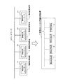
ソフトウェアセルの使用による分散処理の結果、図11の上段に示すようにネットワーク9に接続されている複数の情報処理装置1、2、3、4は、図11の下段に示すように、仮想的な1台の情報処理装置7として動作する。ただし、そのためには、以下のような構成によって、以下のような処理が実行される必要がある。
As a result of distributed processing using software cells, a plurality of
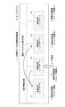
図12に、個々の情報処理コントローラのメインメモリ26が記憶するソフトウェアの構成を示す。これらのソフトウェア(プログラム)は、情報処理装置に電源が投入される前においては、当該の情報処理コントローラに接続される外部記録部28に記録されているものである。各プログラムは、機能または特徴によって、制御プログラム、機能プログラム及びデバイスドライバにカテゴライズされる。 FIG. 12 shows the configuration of software stored in the main memory 26 of each information processing controller. These software (programs) are recorded in the external recording unit 28 connected to the information processing controller before the information processing apparatus is turned on. Each program is categorized into a control program, a function program, and a device driver according to functions or features.
制御プログラムは、各情報処理コントローラが同じものを備え、各情報処理コントローラのメインプロセッサ21が実行するもので、後述のMS(マスター/スレーブ)マネージャ及び能力交換プログラムを含む。 The control program is the same for each information processing controller, and is executed by the main processor 21 of each information processing controller, and includes an MS (master / slave) manager and a capacity exchange program described later.
機能プログラムは、メインプロセッサ21が実行するもので、記録用、再生用、素材検索用など、情報処理コントローラごとに情報処理装置に応じたものが備えられる。 The function program is executed by the main processor 21, and a function program corresponding to the information processing apparatus is provided for each information processing controller such as recording, reproduction, and material search.
デバイスドライバは、情報処理コントローラ(情報処理装置)の入出力(送受信)用で、放送受信、モニタ出力、ビットストリーム入出力、ネットワーク入出力など、情報処理コントローラ毎に情報処理装置に応じたものが備えられる。 The device driver is for input / output (transmission / reception) of the information processing controller (information processing apparatus), such as broadcast reception, monitor output, bit stream input / output, network input / output, etc. Provided.
情報処理装置が物理的にネットワーク9に接続された状態で、情報処理装置に主電源が投入され、情報処理装置が電気的・機能的にもネットワーク9に接続されると、その情報処理装置の情報処理コントローラのメインプロセッサ21は、制御プログラムに属する各プログラム、及びデバイスドライバに属する各プログラムを、メインメモリ26にロードする。 When the information processing apparatus is physically connected to the network 9 and the main power is turned on, and the information processing apparatus is electrically and functionally connected to the network 9, the information processing apparatus The main processor 21 of the information processing controller loads each program belonging to the control program and each program belonging to the device driver into the main memory 26.
ロード手順としては、メインプロセッサ21は、まず、DC27に読み出し命令を実行させることによって、外部記録部28からプログラムを読み出し、次に、DMAC25に書き込み命令を実行させることによって、そのプログラムをメインメモリ26に書き込む。 As a loading procedure, the main processor 21 first reads a program from the external recording unit 28 by causing the DC 27 to execute a read command, and then causes the DMAC 25 to execute a write command to load the program into the main memory 26. Write to.
機能プログラムに属する各プログラムについては、必要なときに必要なプログラムだけをロードするように構成してもよく、または、他のカテゴリに属するプログラムと同様に、主電源投入直後に各プログラムをロードするように構成してもよい。 As for each program belonging to the function program, it may be configured to load only the necessary program when necessary, or like the programs belonging to other categories, each program is loaded immediately after the main power is turned on. You may comprise as follows.
ここで、機能プログラムに属する各プログラムは、ネットワークに接続された全ての情報処理装置の外部記録部28に記録されている必要はなく、いずれか1つの情報処理装置の外部記録部28に記録されていれば、前述の方法によって他の情報処理装置からロードすることができるので、結果的に図11の下段に示すように、仮想的な1台の情報処理装置7として機能プログラムを実行することができる。 Here, each program belonging to the function program does not need to be recorded in the external recording unit 28 of all information processing apparatuses connected to the network, and is recorded in the external recording unit 28 of any one information processing apparatus. If so, it can be loaded from another information processing apparatus by the above-described method. As a result, the function program is executed as one virtual information processing apparatus 7 as shown in the lower part of FIG. Can do.
また、前述したようにメインプロセッサ21によって処理される機能プログラムは、サブプロセッサ23によって処理されるサブプロセッサプログラムと連携動作する場合がある。そこでメインプロセッサ21が外部記録部28から機能プログラムを読み出し、メインメモリ26に書き込む際に対象となる機能プログラムと連携動作するサブプロセッサプログラムが存在する場合には、当該サブプロセッサプログラムも併せて同じメインメモリ26に書き込むものとする。この場合、連携動作するサブプロセッサプログラムは1個である場合もあるし、複数個であることもあり得る。複数個である場合には、全ての連携動作するサブプロセッサプログラムをメインメモリ26に書き込むことになる。メインメモリ26に書き込まれたサブプロセッサプログラムはその後、サブプロセッサ23内のLS24に書き込まれ、メインプロセッサ21によって処理される機能プログラムと連携動作する。 Further, as described above, the function program processed by the main processor 21 may cooperate with the sub processor program processed by the sub processor 23. Therefore, when the main processor 21 reads out the function program from the external recording unit 28 and writes it to the main memory 26, when there is a sub processor program that operates in cooperation with the target function program, the sub processor program also includes the same main program. It is assumed that data is written in the memory 26. In this case, there may be one or more sub-processor programs that operate in cooperation with each other. If there are a plurality of sub-processor programs, all the sub-processor programs operating in cooperation are written in the main memory 26. The sub processor program written in the main memory 26 is then written in the LS 24 in the sub processor 23 and operates in cooperation with the function program processed by the main processor 21.
図9のソフトウェアセルに示したように、機能プログラムには、プログラムごとにプログラムを一意的に識別できる識別子が、機能プログラムIDとして割り当てられる。機能プログラムIDは、機能プログラムの作成の段階で、作成日時や情報処理装置IDなどから決定される。 As shown in the software cell of FIG. 9, an identifier that can uniquely identify a program for each program is assigned to the function program as a function program ID. The function program ID is determined from the creation date and time, the information processing apparatus ID, and the like at the stage of creating the function program.
そしてサブプロセッサプログラムにもサブプロセッサプログラムIDが割り当てられ、これによりサブプロセッサプログラムを一意的に識別可能である。割り当てられるサブプロセッサプログラムIDは、連携動作する相手となる機能プログラムの機能プログラムIDと関連性のある識別子、例えば機能プログラムIDを親番号とした上で最後尾に枝番号を付加させたもの等であることもあり得るし、連携動作する相手となる機能プログラムの機能プログラムIDとは関連性のない識別子であってもよい。いずれにしても機能プログラムとサブプロセッサプログラムが連携動作する場合には、両者とも相手の識別子であるプログラムIDを自プログラム内に互いに記憶しておく必要がある。機能プログラムが複数個のサブプロセッサプログラムと連携動作する場合にも、当該機能プログラムは複数個ある全てのサブプロセッサプログラムのサブプロセッサプログラムIDを記憶しておくことになる。 A sub processor program ID is also assigned to the sub processor program, whereby the sub processor program can be uniquely identified. The assigned sub processor program ID is an identifier related to the function program ID of the function program that is the partner of the cooperative operation, for example, the function program ID as a parent number and a branch number added at the end. There may be an identifier that is not related to the function program ID of the function program that is the partner of the cooperative operation. In any case, when the function program and the sub processor program operate in cooperation, it is necessary to store the program ID which is the identifier of the other party in the own program. Even when the function program operates in cooperation with a plurality of sub processor programs, the function program stores the sub processor program IDs of all the sub processor programs.
メインプロセッサ21は、自身が動作する情報処理装置の装置情報(動作状態に関する情報)を格納するための領域をメインメモリ26に確保し、当該情報を自装置の装置情報テーブルとして記録する。ここでの装置情報は、図10に示した情報処理装置ID以下の各情報である。 The main processor 21 secures an area for storing device information (information regarding the operation state) of the information processing device on which the main processor 21 operates in the main memory 26, and records the information as a device information table of the own device. The device information here is each piece of information below the information processing device ID shown in FIG.
上述したネットワークシステムでは、ある情報処理装置への主電源投入時、その情報処理装置の情報処理コントローラのメインプロセッサ21は、マスター/スレーブマネージャ(以下、MSマネージャ)をメインメモリ26にロードし、実行する。 In the network system described above, when the main power supply to a certain information processing apparatus is turned on, the main processor 21 of the information processing controller of the information processing apparatus loads a master / slave manager (hereinafter referred to as MS manager) into the main memory 26 and executes it. To do.
MSマネージャは、自身が動作する情報処理装置がネットワーク9に接続されていることを検知すると、同じネットワーク9に接続されている他の情報処理装置の存在を確認する。ここでの「接続」または「存在」は、上述したように、情報処理装置が物理的にネットワーク9に接続されているだけでなく、電気的・機能的にもネットワーク9に接続されていることを示す。また、自身が動作する情報処理装置を自装置、他の情報処理装置を他装置と称する。当該装置も、当該情報処理装置を示すものとする。 When the MS manager detects that the information processing apparatus on which it operates is connected to the network 9, it confirms the existence of another information processing apparatus connected to the same network 9. The “connection” or “existence” here means that the information processing apparatus is not only physically connected to the network 9 but also electrically and functionally connected to the network 9 as described above. Indicates. In addition, an information processing apparatus in which the device operates is referred to as a self device, and another information processing device is referred to as another device. The apparatus also indicates the information processing apparatus.
MSマネージャが同じネットワーク9に接続されている他の情報処理装置の存在を確認する方法を以下に示す。 A method in which the MS manager confirms the existence of another information processing apparatus connected to the same network 9 will be described below.
MSマネージャは、DMAコマンドがステータス要求コマンドであり、送信元ID及び応答先IDが当該情報処理装置で、送信先IDを特定しないソフトウェアセルを生成して、当該情報処理装置が接続されたネットワーク上に送信して、ネットワーク接続確認用のタイマーを設定する。タイマーのタイムアウト時間は、例えば10分とされる。 The MS manager generates a software cell in which the DMA command is a status request command, the transmission source ID and the response destination ID are the information processing apparatus, and the transmission destination ID is not specified, and the network manager is connected to the information processing apparatus. To set a timer for network connection confirmation. The timeout time of the timer is, for example, 10 minutes.
当該ネットワークシステム上に他の情報処理装置が接続されている場合、その他装置は、上記ステータス要求コマンドのソフトウェアセルを受信し、上記応答先IDで特定されるステータス要求コマンドを発行した情報処理装置に対して、DMAコマンドがステータス返信コマンドであり、かつデータとして自身(その他装置)の装置情報を含むソフトウェアセルを送信する。このステータス返信コマンドのソフトウェアセルには、少なくとも当該他装置を特定する情報(情報処理装置ID、メインプロセッサに関する情報、サブプロセッサに関する情報など)及び当該他装置のMSステータスが含まれる。 When another information processing apparatus is connected to the network system, the other apparatus receives the software cell of the status request command, and sends it to the information processing apparatus that has issued the status request command specified by the response destination ID. On the other hand, the DMA command is a status return command, and a software cell including device information of itself (other device) is transmitted as data. The software cell of the status reply command includes at least information for identifying the other device (information processing device ID, information on the main processor, information on the sub processor, etc.) and the MS status of the other device.
ステータス要求コマンドを発行した情報処理装置のMSマネージャは、上記ネットワーク接続確認用のタイマーがタイムアウトするまで、当該ネットワーク上の他装置から送信されるステータス返信コマンドのソフトウェアセルの受信を監視する。その結果、MSステータス=0(マスター装置)を示すステータス返信コマンドが受信された場合には、自装置の装置情報テーブルにおけるMSステータスを1に設定する。これによって、当該装置は、スレーブ装置となる。 The MS manager of the information processing apparatus that has issued the status request command monitors the reception of the software cell of the status reply command transmitted from another apparatus on the network until the timer for network connection confirmation times out. As a result, when the status reply command indicating the MS status = 0 (master device) is received, the MS status in the device information table of the own device is set to 1. Thus, the device becomes a slave device.
一方、上記ネットワーク接続確認用のタイマーがタイムアウトするまでの間にステータス返信コマンドが全く受信されなかった場合、またはMSステータス=0(マスター装置)を示すステータス返信コマンドが受信されなかった場合には、自装置の装置情報テーブルにおけるMSステータスを0に設定する。これによって、当該装置は、マスター装置となる。 On the other hand, if no status reply command is received before the network connection confirmation timer times out, or if no status reply command indicating MS status = 0 (master device) is received, The MS status in the device information table of the own device is set to 0. This makes the device a master device.
すなわち、いずれの装置もネットワーク9に接続されていない状態、またはネットワーク9上にマスター装置が存在しない状態において、新たな情報処理装置がネットワーク9に接続されると、当該装置は自動的にマスター装置として設定される。一方、ネットワーク9上に既にマスター装置が存在する状態において、新たな情報処理装置がネットワーク9に接続されると、当該装置は自動的にスレーブ装置として設定される。 That is, if no information processing apparatus is connected to the network 9 in a state where none of the apparatuses is connected to the network 9 or a master apparatus does not exist on the network 9, the apparatus automatically becomes the master apparatus. Set as On the other hand, when a new information processing apparatus is connected to the network 9 in a state where a master apparatus already exists on the network 9, the apparatus is automatically set as a slave apparatus.
マスター装置及びスレーブ装置のいずれについても、MSマネージャは、定期的にステータス要求コマンドをネットワーク9上の他装置に送信してステータス情報を照会することにより、他装置の状況を監視する。その結果、ネットワーク9に接続されている情報処理装置の主電源が遮断され、またはネットワーク9から情報処理装置が切り離されることにより、予め判定用に設定された所定期間内に特定の他装置からステータス返信コマンドが返信されなかった場合や、ネットワーク9に新たな情報処理装置が接続された場合など、ネットワーク9の接続状態に変化があった場合には、その情報を後述の能力交換プログラムに通知する。 For both the master device and the slave device, the MS manager periodically monitors the status of the other device by sending a status request command to the other device on the network 9 and inquiring status information. As a result, the main power supply of the information processing apparatus connected to the network 9 is cut off or the information processing apparatus is disconnected from the network 9, so that the status from a specific other apparatus within a predetermined period set in advance for determination When there is a change in the connection state of the network 9, such as when a reply command is not returned or when a new information processing apparatus is connected to the network 9, the information is notified to the ability exchange program described later. .
メインプロセッサ21は、MSマネージャから、ネットワーク9上の他装置の照会及び自装置のMSステータスの設定完了の通知を受けると、能力交換プログラムを実行する。 When the main processor 21 receives an inquiry from another manager on the network 9 and a notification of completion of setting the MS status of the own apparatus from the MS manager, the main processor 21 executes the capability exchange program.
能力交換プログラムは、自装置がマスター装置である場合には、ネットワーク9に接続されている全ての他装置の装置情報、すなわち各スレーブ装置の装置情報を取得する。他装置の装置情報の取得は、上述したように、DMAコマンドがステータス要求コマンドであるソフトウェアセルを生成して他装置に送信し、その後、DMAコマンドがステータス返信コマンドで、かつデータとして他装置の装置情報を含むソフトウェアセルを他装置から受信することによって可能である。 When the own device is a master device, the capability exchange program acquires device information of all other devices connected to the network 9, that is, device information of each slave device. As described above, the device information of another device is generated by generating a software cell in which the DMA command is a status request command and transmitting it to the other device. Thereafter, the DMA command is a status return command and data of the other device. This is possible by receiving a software cell containing device information from another device.
能力交換プログラムは、マスター装置である自装置の装置情報テーブルと同様に、ネットワーク9に接続されている全ての他装置(各スレーブ装置)の装置情報を格納するための領域を自装置のメインメモリ26に確保し、これら情報を他装置(スレーブ装置)の装置情報テーブルとして記録する。すなわち、マスター装置のメインメモリ26には、自装置を含むネットワーク9に接続されている全ての情報処理装置の装置情報が、装置情報テーブルとして記録される。 Similar to the device information table of the own device that is the master device, the capability exchange program sets an area for storing device information of all other devices (each slave device) connected to the network 9 as the main memory of the own device. This information is recorded in a device information table of another device (slave device). That is, the device information of all information processing devices connected to the network 9 including the device itself is recorded in the main memory 26 of the master device as a device information table.
一方、自装置がスレーブ装置である場合には、能力交換プログラムは、ネットワーク9に接続されている全ての他装置の装置情報、すなわちマスター装置及び自装置以外の各スレーブ装置の装置情報を取得し、これら装置情報に含まれる情報処理装置ID及びMSステータスを、自装置のメインメモリ26に記録する。すなわち、スレーブ装置のメインメモリ26には、自装置の装置情報が、装置情報テーブルとして記録されるとともに、自装置以外のネットワーク9に接続されているマスター装置及び各スレーブ装置についての情報処理装置ID及びMSステータスが、別の装置情報テーブルとして記録される。 On the other hand, when the own device is a slave device, the capability exchange program acquires device information of all other devices connected to the network 9, that is, device information of each slave device other than the master device and the own device. The information processing apparatus ID and the MS status included in the apparatus information are recorded in the main memory 26 of the own apparatus. That is, the device information of the own device is recorded as a device information table in the main memory 26 of the slave device, and the master device connected to the network 9 other than the own device and the information processing device ID for each slave device. And the MS status are recorded as another device information table.
また、マスター装置及びスレーブ装置のいずれについても、能力交換プログラムは、上記のようにMSマネージャから、新たにネットワーク9に情報処理装置が接続されたことが通知されたときには、その情報処理装置の装置情報を取得し、上述したようにメインメモリ26に記録する。 Further, in both the master device and the slave device, when the capability exchange program is notified from the MS manager that the information processing device is newly connected to the network 9 as described above, the device of the information processing device Information is acquired and recorded in the main memory 26 as described above.
なお、MSマネージャ及び能力交換プログラムは、メインプロセッサ21で実行されることに限らず、いずれかのサブプロセッサ23で実行されてもよい。また、MSマネージャ及び能力交換プログラムは、情報処理装置の主電源が投入されている間は常時動作する常駐プログラムであることが望ましい。 Note that the MS manager and the capability exchange program are not limited to being executed by the main processor 21, but may be executed by any of the sub processors 23. The MS manager and the capability exchange program are preferably resident programs that always operate while the main power supply of the information processing apparatus is turned on.
マスター装置及びスレーブ装置のいずれについても、能力交換プログラムは、上記のようにMSマネージャから、ネットワーク9に接続されている情報処理装置の主電源が遮断され、またはネットワーク9から情報処理装置が切り離されたことが通知されたときには、その情報処理装置の装置情報テーブルを自装置のメインメモリ26から削除する。 For both the master device and the slave device, the capability exchange program causes the MS manager to cut off the main power supply of the information processing device connected to the network 9 or disconnect the information processing device from the network 9 as described above. When it is notified, the apparatus information table of the information processing apparatus is deleted from the main memory 26 of the own apparatus.
更に、このようにネットワーク9から切断された情報処理装置がマスター装置である場合には、以下のような方法によって、新たにマスター装置が決定される。 Further, when the information processing apparatus disconnected from the network 9 is a master apparatus, a new master apparatus is determined by the following method.
具体的には、例えば、ネットワーク9から切断されていない情報処理装置は、それぞれ、自装置及び他装置の情報処理装置IDを数値に置き換えて、自装置の情報処理装置IDを他装置の情報処理装置IDと比較し、自装置の情報処理装置IDがネットワーク9から切断されていない情報処理装置中で最小である場合、そのスレーブ装置は、マスター装置に移行して、MSステータスを0に設定し、マスター装置として、上述したように、ネットワーク9に接続されている全ての他装置(各スレーブ装置)の装置情報を取得して、メインメモリ26に記録する。 Specifically, for example, each of the information processing apparatuses that are not disconnected from the network 9 replaces the information processing apparatus ID of the own apparatus and the other apparatus with a numerical value, and sets the information processing apparatus ID of the own apparatus to the information processing of the other apparatus. If the information processing device ID of the own device is the smallest among the information processing devices not disconnected from the network 9 as compared with the device ID, the slave device moves to the master device and sets the MS status to 0. As described above, device information of all other devices (each slave device) connected to the network 9 is acquired and recorded in the main memory 26 as a master device.
図11の下段に示したようにネットワーク9に接続されている複数の情報処理装置1、2、3、4を仮想的な1台の情報処理装置7として動作させるためには、マスター装置がユーザの操作及びスレーブ装置の動作状態を把握する必要がある。
As shown in the lower part of FIG. 11, in order for a plurality of
図13に、4台の情報処理装置が仮想的な1台の情報処理装置7として動作する様子を示す。情報処理装置1がマスター装置、情報処理装置2、3、4がスレーブ装置A、B、Cとして、動作しているものとする。
FIG. 13 shows a state in which four information processing apparatuses operate as one virtual information processing apparatus 7. It is assumed that the
ユーザがネットワーク9に接続されている情報処理装置を操作した場合、操作対象がマスター装置1であれば、その操作情報は、マスター装置1において直接把握され、操作対象がスレーブ装置であれば、その操作情報は、操作されたスレーブ装置からマスター装置1に送信される。すなわち、ユーザの操作対象がマスター装置1とスレーブ装置のいずれであるかにかかわらず、その操作情報は常にマスター装置1において把握される。操作情報の送信は、例えば、DMAコマンドが操作情報送信コマンドであるソフトウェアセルによって行われる。
When the user operates an information processing device connected to the network 9, if the operation target is the
そして、マスター装置1内の情報処理コントローラ11に含まれるメインプロセッサ21−1は、その操作情報に従って、実行する機能プログラムを選択する。その際、必要であれば、マスター装置1内の情報処理コントローラ11に含まれるメインプロセッサ21−1は、上記の方法によって自装置の外部記録部28−1、28−2からメインメモリ26−1に機能プログラムをロードするが、他の情報処理装置(スレーブ装置)がマスター装置1に機能プログラムを送信してもよい。
Then, the main processor 21-1 included in the
機能プログラムには、その実行単位毎に必要となる、図10に示した各情報として表される情報処理装置種別ID、メインプロセッサまたはサブプロセッサの処理能力、メインメモリ使用量、外部記録部に関する条件等の、装置に関する要求スペックが規定されている。 In the function program, information processing apparatus type IDs represented as information shown in FIG. 10, main processor or sub-processor processing capacity, main memory usage, and conditions related to the external recording unit are required for each execution unit. The required specifications regarding the device are defined.
マスター装置1内の情報処理コントローラ11に含まれるメインプロセッサ21−1は、各機能プログラムについて必要となる上記要求スペックを読み出す。また、予め能力交換プログラムによってメインメモリ26−1に記録された装置情報テーブルを参照し、各情報処理装置の装置情報を読み出す。ここでの装置情報は、図10に示した情報処理装置ID以下の各情報を示し、メインプロセッサ、サブプロセッサ、メインメモリ及び外部記録部に関する情報である。
The main processor 21-1 included in the
マスター装置1内の情報処理コントローラ11に含まれるメインプロセッサ21−1は、ネットワーク9上に接続された各情報処理装置の上記装置情報と、機能プログラム実行に必要となる上記要求スペックとを順次比較する。
The main processor 21-1 included in the
そして、例えば、機能プログラムが録画機能を必要とする場合には、情報処理装置種別IDに基づいて、録画機能を有する情報処理装置のみを特定して抽出する。更に、機能プログラムを実行するために必要なメインプロセッサまたはサブプロセッサの処理能力、メインメモリ使用量、外部記録部に関する条件を確保できるスレーブ装置を、実行要求候補装置として特定する。ここで、複数の実行要求候補装置が特定された場合には、当該候補装置から1つの実行要求候補装置を特定して選択する。 For example, when the function program requires a recording function, only the information processing apparatus having the recording function is specified and extracted based on the information processing apparatus type ID. Furthermore, a slave device that can secure the conditions regarding the processing capability of the main processor or sub processor, the amount of main memory used, and the external recording unit necessary for executing the function program is specified as an execution request candidate device. Here, when a plurality of execution request candidate devices are specified, one execution request candidate device is specified and selected from the candidate devices.
実行要求するスレーブ装置が特定されたら、マスター装置1内の情報処理コントローラ11に含まれるメインプロセッサ21−1は、その特定されたスレーブ装置について、自装置内の情報処理コントローラ11に含まれるメインメモリ26−1に記録されている当該スレーブ装置の装置情報テーブルを更新する。
When the slave device to be executed is specified, the main processor 21-1 included in the
更に、マスター装置1内の情報処理コントローラ11に含まれるメインプロセッサ21−1は、DMAコマンドがロードコマンド及びキックコマンドであるソフトウェアセルを生成し、当該ソフトウェアセルのセルインターフェースに、機能プログラムに関する必要なサブプロセッサの情報及びサンドボックスサイズ(図9参照)を設定して、上記実行要求されるスレーブ装置に対して送信する。
Further, the main processor 21-1 included in the
機能プログラムの実行を要求されたスレーブ装置は、その機能プログラムを実行するとともに、自装置の装置情報テーブルを更新する。その際、必要であれば、スレーブ装置内の情報処理コントローラに含まれるメインプロセッサ21は、上記の方法によって自装置の外部記録部28からメインメモリ26に機能プログラムおよび当該機能プログラムと連携動作するサブプロセッサプログラムをロードする。 The slave device requested to execute the function program executes the function program and updates the device information table of the own device. At that time, if necessary, the main processor 21 included in the information processing controller in the slave device, from the external recording unit 28 of the own device to the main memory 26 by the above method, the function program and the sub-operation that operates in cooperation with the function program. Load the processor program.
機能プログラムの実行を要求されたスレーブ装置の外部記録部28に、必要な機能プログラムまたは当該機能プログラムと連携動作するサブプロセッサプログラムが記録されていない場合には、他の情報処理装置が当該機能プログラムまたはサブプロセッサプログラムを、その機能プログラム実行要求先スレーブ装置に送信するように、システムを構成すればよい。 When the required function program or the sub processor program that operates in cooperation with the function program is not recorded in the external recording unit 28 of the slave device requested to execute the function program, the other information processing apparatus Alternatively, the system may be configured so that the sub processor program is transmitted to the function program execution request destination slave device.
サブプロセッサプログラムについては、前述のロードコマンドおよびキックコマンドを利用して他の情報処理装置に実行させることもできる。 The sub-processor program can be executed by another information processing apparatus using the aforementioned load command and kick command.
機能プログラムの実行終了後、機能プログラムを実行したスレーブ装置内の情報処理コントローラに含まれるメインプロセッサ21は、終了通知をマスター装置1内の情報処理コントローラ11に含まれるメインプロセッサ21−1に送信するとともに、自装置の装置情報テーブルを更新する。マスター装置1内の情報処理コントローラ11に含まれるメインプロセッサ21−1は、その終了通知を受信して、機能プログラムを実行したスレーブ装置の装置情報テーブルを更新する。
After the execution of the function program, the main processor 21 included in the information processing controller in the slave device that has executed the function program transmits an end notification to the main processor 21-1 included in the
マスター装置1内の情報処理コントローラ11に含まれるメインプロセッサ21−1は、自装置及び他装置の装置情報テーブルの参照結果から、当該の機能プログラムを実行することができる情報処理装置として、自身を選択する場合もあり得る。その場合には、マスター装置1が当該機能プログラムを実行する。
The main processor 21-1 included in the
図13の例で、ユーザがスレーブ装置A(情報処理装置2)を操作し、当該操作に応じた機能プログラムを別のスレーブ装置B(情報処理装置3)が実行する場合について、図14を用いてその分散処理の例を説明する。 In the example of FIG. 13, a case where the user operates the slave device A (information processing device 2) and another slave device B (information processing device 3) executes a function program corresponding to the operation is described with reference to FIG. An example of the distributed processing will be described.
図14の例では、ユーザがスレーブ装置Aを操作することによって、スレーブ装置Aを含むネットワークシステム全体の分散処理が開始して、まず、スレーブ装置Aは、ステップ81で、その操作情報をマスター装置1に送信する。 In the example of FIG. 14, when the user operates the slave device A, the distributed processing of the entire network system including the slave device A starts. First, in step 81, the slave device A transmits the operation information to the master device. 1 to send.
マスター装置1は、ステップ72で、その操作情報を受信し、さらにステップ73に進んで、自装置のメインメモリ26−1に記録されている自装置及び他装置の装置情報テーブルから、各情報処理装置の動作状態を調べて、受信した操作情報に応じた機能プログラムを実行することができる情報処理装置を選択する。この例は、スレーブ装置Bが選択される場合である。
In step 72, the
次に、マスター装置1は、ステップ74で、その選択したスレーブ装置Bに対して機能プログラムの実行を要求する。
Next, in step 74, the
スレーブ装置Bは、ステップ95で、その実行要求を受信し、さらにステップ96に進んで、実行要求された機能プログラムを実行する。 In step 95, the slave device B receives the execution request, and further proceeds to step 96 to execute the function program requested to be executed.
以上のように、ユーザは、1台の情報処理装置のみを操作することによって、他の情報処理装置を操作することなく、複数の情報処理装置1、2、3、4を仮想的な1台の情報処理装置7として動作させることができる。
As described above, by operating only one information processing apparatus, the user operates a plurality of
次に、以上説明したネットワークシステムを、家庭内制御システムに適用した場合の実施の形態について説明する。図15は、本実施形態におけるシステムの構成を示した図である。同図においては、上述の図7における情報処理装置1に上述のHDDレコーダ100を適用している。同図において、図1、図7等と同様の構成となる部分については同一の符号を付して説明を簡略または省略し、異なる点を中心に説明する。
Next, an embodiment when the network system described above is applied to a home control system will be described. FIG. 15 is a diagram showing a system configuration in the present embodiment. In the figure, the
図示しないが、HDDレコーダ100は、上記図2で説明したような各種ソフトウェア201〜204及び対応情報データベース205を有し、機能コマンドをリズムパターンと対応付けて予め登録して、リズムパターンの入力により対応する機能コマンドを実行することが可能である。また、上記図7における情報処理装置1のメインメモリ26−1に上記第1実施形態の図1におけるRAM110を、外部記憶部26−1及び26−2に図1におけるROM111及びHDD103を適用している。
Although not shown, the
HDDレコーダ100は上述の図7等における情報処理装置1として、デスクトップPC31は情報処理装置2として、ノートPC32は情報処理装置3として機能し、それぞれ上述のメインプロセッサ、サブプロセッサを含む情報処理コントローラを有し、上記DMAコマンド等によりソフトウェアセルを実行したり、各種データをやり取りしたりすることが可能である。よって、各機器には、それぞれを識別するための上記情報処理装置IDが付与されている。
The
図15に示すように、本実施形態においては、HDDレコーダと100とデスクトップPC31及びノートPC32がLAN(Local Area Network)30を介して接続されており、互いに通信を行うことが可能である。そして、HDDレコーダ100は、上述した自身の機能を実行することができるほか、ホームサーバとして上記対応情報データベース205に自身のデータともにデスクトップPC31及びノートPC32の各対応情報データベースを集約して有しており、HDDレコーダ100上で照合されたリズムパターンが他の機器の機能に対応するものであっても、その情報をLAN30を介して対象機器に受け渡して、当該機器においてユーザが所望の機能を実行させることが可能である。なお、この場合、HDDレコーダ100は上記マスター装置として、デスクトップPC31及びノートPC32は上記スレーブ装置として機能する。
As shown in FIG. 15, in this embodiment, the HDD recorder, 100, the desktop PC 31, and the notebook PC 32 are connected via a LAN (Local Area Network) 30, and can communicate with each other. The
より具体的には、HDDレコーダ100は、上記デスクトップPC31またはノートPC32に入力されたリズムパターンを受信し、上記対応情報データベース205を参照して当該リズムパターンを照合して対応する機能コマンドを検索し、検索した機能コマンドを上記ノートPC32またはデスクトップPC31に送信して実行させるようなことが可能である。なお、図示しないが、上記対応情報データベース205には、上記第1の実施形態において説明したデータの他、HDDレコーダ100、デスクトップPC31及びノートPC32の各機器を識別する上記情報処理装置IDが上記リズムパターン情報と関連付けられており、どの機器の機能コマンドを実行させるためのリズムパターンであるかが認識できるようになっている。
More specifically, the
例として、ユーザがノートPC32においてMP3(MPEG-1 Audio Layer-3)ファイルを再生させたい場合に、デスクトップPC31の図示しないマウスまたはキーボードの入力により上記MP3ファイルの再生という機能コマンドと予め対応付けて登録しておいたリズムパターンの入力を行い、当該入力を上記HDDレコーダ100が認識して、それに対応する機能コマンドをノートPC32へ送信して再生させるという場合について説明する。
As an example, when the user wants to play an MP3 (MPEG-1 Audio Layer-3) file on the notebook PC 32, it is associated in advance with a function command for playing the MP3 file by inputting a mouse or keyboard (not shown) on the desktop PC 31. A case will be described in which a registered rhythm pattern is input, the
この場合は、例えばユーザがMP3プレイヤ及びデコーダを有さないデスクトップPC31上で作業を行っている最中に、ユーザとは離れた位置に存在するノートPC32上でMP3ファイルを再生させたいような場合を想定している。 In this case, for example, when the user is working on the desktop PC 31 that does not have the MP3 player and decoder, the user wants to play the MP3 file on the notebook PC 32 that is located away from the user. Assumed.
図16は、この場合にまずデスクトップPC31がHDDレコーダ100に対して送信するソフトウェアセルの例を示した図である。
FIG. 16 is a diagram showing an example of a software cell that the desktop PC 31 first transmits to the
同図に示すように、このソフトウェアセルにおいて、送信元IDはデスクトップPC31の情報処理装置ID、送信先IDはHDDレコーダ100の情報処理装置ID、応答先IDはノートPC32の情報処理装置IDである。
As shown in the figure, in this software cell, the transmission source ID is the information processing device ID of the desktop PC 31, the transmission destination ID is the information processing device ID of the
またDMAコマンドとしてコマンド検索・実行要求コマンドを送信し、データとして、デスクトップPC31においてユーザが上記マウスまたはキーボードにより入力したリズムパターンを示す上記入力イベント発生時刻、入力イベント回数及び総入力時間のデジタルデータを送信する。更に、デスクトップPC31が当該ソフトウェアセル以前にもHDDレコーダ100に対してソフトウェアセルを送信している場合には、セルインターフェース中、前回のソフトウェアセルIDとして、前回送信した際のソフトウェアセルのグローバルIDを送信する。
Also, a command search / execution request command is transmitted as a DMA command, and digital data of the input event occurrence time, the number of input events, and the total input time indicating the rhythm pattern input by the user with the mouse or keyboard on the desktop PC 31 is used as data. Send. Further, when the desktop PC 31 has transmitted a software cell to the
図17は、上記コマンド検索・実行要求コマンドを含むソフトウェアセルを受信したHDDレコーダ100が、上記ノートPC32に対して送信するソフトウェアセルの例を示した図である。
FIG. 17 is a diagram showing an example of a software cell transmitted to the notebook PC 32 by the
同図に示すように、このソフトウェアセルにおいて、送信元IDはHDDレコーダ100の情報処理装置ID、送信先ID及び応答先IDはノートPC32の情報処理装置IDである。
As shown in the figure, in this software cell, the transmission source ID is the information processing device ID of the
またDMAコマンドとして、HDDレコーダが上記リズムパターンの照合・検索により抽出した機能コマンド、すなわちMP3ファイルの再生実行要求コマンドを送信する。更に、HDDレコーダ100が当該ソフトウェアセル以前にもノートPC32に対してソフトウェアセルを送信している場合には、セルインターフェース中、前回のソフトウェアセルIDとして、前回送信した際のソフトウェアセルのグローバルIDを送信する。
Also, as the DMA command, the function command extracted by the HDD recorder by the collation / search of the rhythm pattern, that is, the MP3 file reproduction execution request command is transmitted. Further, when the
次に、以上のように構成された家庭内制御システムにおいて、デスクトップPC31から送信されたリズムパターンに対応する機能コマンドがノートPC32において実行されるまでの動作を説明する。図18は当該動作の流れを示したシーケンス図である。 Next, in the home control system configured as described above, an operation until a function command corresponding to a rhythm pattern transmitted from the desktop PC 31 is executed on the notebook PC 32 will be described. FIG. 18 is a sequence diagram showing the flow of the operation.
同図に示すように、まず、デスクトップPC31は、ユーザからマウスまたはキーボードによるリズムパターンの入力があると、当該リズムパターンを入力し(ステップ41)、当該リズムパターンを示す上記入力イベント発生時刻、入力イベント回数の各データを記録する。そして、当該データとともに、上記コマンド検索・実行要求コマンドを含むソフトウェアセルをHDDレコーダ100へ送信する(ステップ42)。 As shown in the figure, first, when a rhythm pattern is input from the user by a mouse or a keyboard from the user, the desktop PC 31 inputs the rhythm pattern (step 41), and the input event occurrence time indicating the rhythm pattern, the input Record each event count data. Then, along with the data, a software cell including the command search / execution request command is transmitted to HDD recorder 100 (step 42).
続いて、HDDレコーダ100は、上記ソフトウェアセルを受信し(ステップ43)、当該ソフトウェアセルに含まれる上記各データを基に、上記対応情報データベース205を参照して上記リズムパターンの照合及び検索を行う(ステップ44)。当該照合及び検索処理は、上述の第1実施形態における処理と同様である。次に、HDDレコーダ100は、検索されたリズムパターンに対応する機能コマンドを検索する(ステップ45)。本例においては、当該機能コマンドは、『MP3ファイル○○○の再生』というコマンドである。続いて、当該コマンドを、再生実行要求コマンドとして、上記ソフトウェアセルによりノートPC32へ送信する(ステップ46)。
Subsequently, the
そして、ノートPC32が上記ソフトウェアセルを受信して(ステップ47)、当該ソフトウェアセルに含まれる再生実行要求コマンドを実行することにより、ユーザの所望するMP3ファイルの再生処理が実行される(ステップ48)。 Then, the notebook PC 32 receives the software cell (step 47), and executes the playback execution request command included in the software cell, thereby executing the MP3 file playback process desired by the user (step 48). .
以上の動作により、HDDレコーダ100、デスクトップPC31及びノートPC32が協働して一台の仮想的な情報処理装置として機能することにより、ユーザはデスクトップPC31からマウス等によりリズムパターンを入力するだけでノートPC32において所望の機能を実行させることができる。
Through the above operation, the
なお、上述の場合とは逆に、ノートPC32からリズムパターンの入力を行い、HDDレコーダ100を介して、デスクトップPC31に対応する機能を実行させるような態様であっても勿論構わない。
It should be noted that, contrary to the above-described case, a mode in which a rhythm pattern is input from the notebook PC 32 and a function corresponding to the desktop PC 31 is executed via the
また、上記デスクトップPC31またはノートPC32が、ユーザから入力されたリズムパターンを上記HDDレコーダ100に送信して、対応する機能コマンドを検索させ、HDDレコーダ100から当該対応する機能コマンドを応答させて、当該機能コマンドを自ら実行するような態様であってもよい。すなわち、この場合に送信されるソフトウェアセルにおいて、送信先IDはHDDレコーダ100の情報処理装置IDであり、送信元ID及び応答先IDは、上記デスクトップPC31またはノートPC32を示す同一のIDとなる。
Further, the desktop PC 31 or the notebook PC 32 transmits a rhythm pattern input by the user to the
また、本実施形態においては、リズムパターンを照合するためのパラメータとして入力イベント発生時刻、入力イベント回数及び総入力時間を用いたが、上記第1の実施形態と同様、ボタンを押下している時間長を示す情報や、入力信号のパワーを示す値等もパラメータとして用いることが可能である。 In this embodiment, the input event occurrence time, the number of input events, and the total input time are used as parameters for collating rhythm patterns. However, as in the first embodiment, the time during which the button is pressed. Information indicating the length, a value indicating the power of the input signal, and the like can also be used as parameters.
更に、本実施形態においては、本発明を家庭内の制御システムに適用した例について説明したが、家庭外でも例えばオフィスや店舗等様々な環境で適用することができる。 Furthermore, in this embodiment, although the example which applied this invention to the control system in a home was demonstrated, it can apply in various environments, such as an office and a store, also outside a home.
100…HDDレコーダ
103…HDD
107…通信部
108…赤外線受信部
109…CPU
110…RAM
111…ROM
113…リモートコントローラ
201…リズムパターン入力部
202…機能コマンド登録部
203…リズムパターン照合・検索部
204…登録機能コマンド呼出部
205…リズムパターン‐コマンド対応情報データベース
100 ...
107:
110 ... RAM
111 ... ROM
DESCRIPTION OF
Claims (10)
前記検出された入力信号のリズムパターン情報を、ユーザが指定した制御命令情報と対応付けて記憶する記憶手段と、
前記リズムパターン情報の記憶後のユーザの操作による入力信号を検出する第2の検出手段と、
前記第2の入力手段により検出された入力信号のリズムパターン情報と前記記憶されたリズムパターン情報とを比較する比較手段と、
前記比較手段により、上記両リズムパターン情報が同一または類似であると判断された場合に、前記記憶された制御命令情報を基に、前記記憶されたリズムパターン情報に対応する制御命令を実行する実行手段と
を具備することを特徴とする電子機器装置。 First detection means for detecting a series of input signals by a user operation;
Storage means for storing rhythm pattern information of the detected input signal in association with control command information designated by a user;
Second detection means for detecting an input signal by a user operation after storing the rhythm pattern information;
Comparing means for comparing the rhythm pattern information of the input signal detected by the second input means with the stored rhythm pattern information;
Execution of executing a control command corresponding to the stored rhythm pattern information based on the stored control command information when the comparing means determines that the rhythm pattern information is the same or similar And an electronic device apparatus.
前記記憶手段は、前記リズムパターン情報として、前記第1の検出手段により検出された入力信号の数情報、各入力信号間の時間間隔情報及び入力信号の総時間情報を記憶することを特徴とする電子機器装置。 The electronic device apparatus according to claim 1,
The storage means stores, as the rhythm pattern information, number information of input signals detected by the first detection means, time interval information between the input signals, and total time information of the input signals. Electronic equipment device.
前記判断手段は、前記記憶手段により記憶されたリズムパターン情報と、前記第2の検出手段により検出されたリズムパターン情報とをそれぞれのリズムパターン情報に含まれる総時間情報により正規化したした上で両者を比較することにより類似を判断することを特徴とする電子機器装置。 The electronic device apparatus according to claim 2,
The determination unit normalizes the rhythm pattern information stored by the storage unit and the rhythm pattern information detected by the second detection unit based on total time information included in each rhythm pattern information. An electronic apparatus device characterized by determining similarity by comparing the two.
前記記憶手段により記憶されたリズムパターン情報は、前記ユーザが指定した制御命令から連想されるイメージと関連することを特徴とする電子機器装置。 The electronic device apparatus according to claim 1,
The electronic device apparatus, wherein the rhythm pattern information stored by the storage means is associated with an image associated with a control command designated by the user.
前記ユーザの操作は、ボタンまたはキーボードの押下操作であることを特徴とする電子機器装置。 The electronic device apparatus according to claim 1,
The electronic device apparatus according to claim 1, wherein the user operation is a button or keyboard pressing operation.
前記リズムパターン情報の記憶後のユーザの操作による入力信号のリズムパターン情報を受信する受信手段と、
前記受信されたリズムパターン情報と前記記憶されたリズムパターン情報とを比較する比較手段と、
前記比較手段により、上記両リズムパターン情報が同一または類似であると判断された場合に、前記記憶された制御命令情報及び機器情報を基に、前記記憶されたリズムパターン情報に対応する制御命令を前記制御対象の機器へ送信する送信手段と
を具備することを特徴とするサーバ装置。 Storage means for storing rhythm pattern information of a series of input signals by a user's operation in association with control command information designated by the user and device information related to a device to be controlled;
Receiving means for receiving rhythm pattern information of an input signal by a user operation after storing the rhythm pattern information;
A comparison means for comparing the received rhythm pattern information with the stored rhythm pattern information;
When the comparing means determines that the rhythm pattern information is the same or similar, a control command corresponding to the stored rhythm pattern information is obtained based on the stored control command information and device information. And a transmission unit configured to transmit to the device to be controlled.
前記入力された操作のリズムパターン情報を、ユーザが指定した制御命令情報と対応付けて記憶するステップと、
前記リズムパターン情報の記憶後のユーザの操作を入力するステップと、
前記リズムパターン情報の記憶後に入力された操作のリズムパターン情報と前記記憶されたリズムパターン情報とを比較するステップと、
前記比較の結果、上記両リズムパターン情報が同一または類似であると判断された場合に、前記記憶された制御命令情報を基に、前記記憶されたリズムパターン情報に対応する制御命令を実行するステップと
を具備することを特徴とする制御方法。 Entering user actions; and
Storing the rhythm pattern information of the input operation in association with the control command information designated by the user;
Inputting a user operation after storing the rhythm pattern information;
Comparing the rhythm pattern information of the operation input after storing the rhythm pattern information with the stored rhythm pattern information;
A step of executing a control command corresponding to the stored rhythm pattern information based on the stored control command information when it is determined that the rhythm pattern information is the same or similar as a result of the comparison; And a control method comprising:
前記リズムパターン情報の記憶後のユーザの操作のリズムパターン情報を受信するステップと、
前記受信されたリズムパターン情報と前記記憶されたリズムパターン情報とを比較するステップと、
前記比較の結果、上記両リズムパターン情報が同一または類似であると判断された場合に、前記記憶された制御命令情報及び機器情報を基に、前記記憶されたリズムパターン情報に対応する制御命令を前記制御対象の機器へ送信するステップと
を具備することを特徴とする制御方法。 Storing the rhythm pattern information of the operation input by the user in association with the control command information designated by the user and the device information related to the device to be controlled;
Receiving rhythm pattern information of a user's operation after storing the rhythm pattern information;
Comparing the received rhythm pattern information with the stored rhythm pattern information;
As a result of the comparison, when it is determined that the rhythm pattern information is the same or similar, a control command corresponding to the stored rhythm pattern information is obtained based on the stored control command information and device information. And a step of transmitting to the device to be controlled.
ユーザの操作を入力するステップと、
前記入力された操作のリズムパターン情報を、ユーザが指定した制御命令情報と対応付けて記憶するステップと、
前記リズムパターン情報の記憶後のユーザの操作を入力するステップと、
前記リズムパターン情報の記憶後に入力された操作のリズムパターン情報と前記記憶されたリズムパターン情報とを比較するステップと、
前記比較の結果、上記両リズムパターン情報が同一または類似であると判断された場合に、前記記憶された制御命令情報を基に、前記記憶されたリズムパターン情報に対応する制御命令を実行するステップ
として機能させるプログラム。 Electronic equipment,
Entering user actions; and
Storing the rhythm pattern information of the input operation in association with the control command information designated by the user;
Inputting a user operation after storing the rhythm pattern information;
Comparing the rhythm pattern information of the operation input after storing the rhythm pattern information with the stored rhythm pattern information;
A step of executing a control command corresponding to the stored rhythm pattern information based on the stored control command information when it is determined that the rhythm pattern information is the same or similar as a result of the comparison; Program to function as.
ユーザにより入力された操作のリズムパターン情報を、ユーザが指定した制御命令情報及び制御対象の機器に関する機器情報と対応付けて記憶するステップと、
前記リズムパターン情報の記憶後のユーザの操作のリズムパターン情報を受信するステップと、
前記受信されたリズムパターン情報と前記記憶されたリズムパターン情報とを比較するステップと、
前記比較の結果、上記両リズムパターン情報が同一または類似であると判断された場合に、前記記憶された制御命令情報及び機器情報を基に、前記記憶されたリズムパターン情報に対応する制御命令を前記制御対象の機器へ送信するステップ
として機能させるプログラム。 Server device
Storing the rhythm pattern information of the operation input by the user in association with the control command information designated by the user and the device information related to the device to be controlled;
Receiving rhythm pattern information of a user's operation after storing the rhythm pattern information;
Comparing the received rhythm pattern information with the stored rhythm pattern information;
As a result of the comparison, when it is determined that the rhythm pattern information is the same or similar, a control command corresponding to the stored rhythm pattern information is obtained based on the stored control command information and device information. A program that functions as a step of transmitting to the device to be controlled.
Priority Applications (1)
| Application Number | Priority Date | Filing Date | Title |
|---|---|---|---|
| JP2004110089A JP2005293408A (en) | 2004-04-02 | 2004-04-02 | Electronic device apparatus, server apparatus, control method and program thereof |
Applications Claiming Priority (1)
| Application Number | Priority Date | Filing Date | Title |
|---|---|---|---|
| JP2004110089A JP2005293408A (en) | 2004-04-02 | 2004-04-02 | Electronic device apparatus, server apparatus, control method and program thereof |
Publications (2)
| Publication Number | Publication Date |
|---|---|
| JP2005293408A true JP2005293408A (en) | 2005-10-20 |
| JP2005293408A5 JP2005293408A5 (en) | 2007-05-17 |
Family
ID=35326242
Family Applications (1)
| Application Number | Title | Priority Date | Filing Date |
|---|---|---|---|
| JP2004110089A Pending JP2005293408A (en) | 2004-04-02 | 2004-04-02 | Electronic device apparatus, server apparatus, control method and program thereof |
Country Status (1)
| Country | Link |
|---|---|
| JP (1) | JP2005293408A (en) |
Cited By (4)
| Publication number | Priority date | Publication date | Assignee | Title |
|---|---|---|---|---|
| JP2010198230A (en) * | 2009-02-24 | 2010-09-09 | Nomura Research Institute Ltd | Processing device |
| JP2012089160A (en) * | 2011-12-28 | 2012-05-10 | Nomura Research Institute Ltd | Processing device |
| JP2013504821A (en) * | 2009-09-15 | 2013-02-07 | シマンテック コーポレーション | Use of metadata in security tokens to prevent coordinated cheating in reputation systems |
| US9606644B2 (en) | 2013-02-19 | 2017-03-28 | Gomtech Gmbh | Manually operable input device with code detection |
-
2004
- 2004-04-02 JP JP2004110089A patent/JP2005293408A/en active Pending
Cited By (4)
| Publication number | Priority date | Publication date | Assignee | Title |
|---|---|---|---|---|
| JP2010198230A (en) * | 2009-02-24 | 2010-09-09 | Nomura Research Institute Ltd | Processing device |
| JP2013504821A (en) * | 2009-09-15 | 2013-02-07 | シマンテック コーポレーション | Use of metadata in security tokens to prevent coordinated cheating in reputation systems |
| JP2012089160A (en) * | 2011-12-28 | 2012-05-10 | Nomura Research Institute Ltd | Processing device |
| US9606644B2 (en) | 2013-02-19 | 2017-03-28 | Gomtech Gmbh | Manually operable input device with code detection |
Similar Documents
| Publication | Publication Date | Title |
|---|---|---|
| US9946583B2 (en) | Media player framework | |
| US8893003B2 (en) | Multi-media center for computing systems | |
| US7243307B2 (en) | Customizable database-driven menu structure for a portable computing device | |
| US8276072B2 (en) | Information processing apparatus and information processing method | |
| US7650563B2 (en) | Aggregating metadata for media content from multiple devices | |
| US8443288B2 (en) | Ubiquitous companion agent | |
| US7330874B2 (en) | Information processing apparatus and information processing method | |
| US20060080103A1 (en) | Method and system for network downloading of music files | |
| US8316322B2 (en) | Method for editing playlist and multimedia reproducing apparatus employing the same | |
| US8438145B2 (en) | Methods, systems, and computer program products for determining availability of presentable content via a subscription service | |
| KR20060134850A (en) | Playback device, playback method and playback program | |
| US8386652B2 (en) | Mobile computing device with adaptive response based on accessory firmware | |
| US20070038647A1 (en) | Management of media sources in memory constrained devices | |
| CN112052052A (en) | Touch method and device for key value, terminal and storage medium | |
| JP2006005759A (en) | Server device, playback device, content transmission method, content playback method, content playback system, and program | |
| JP2005293408A (en) | Electronic device apparatus, server apparatus, control method and program thereof | |
| JP2006033646A (en) | Information processing system, information processing method, and computer program | |
| US20070061802A1 (en) | Automatic installation of PC game | |
| KR100829115B1 (en) | Method and device for playing content of mobile communication terminal | |
| JP2005267150A (en) | Information processing system, information processing method, and computer program | |
| JP2002024067A (en) | File management device and recording medium recording program for realizing the file management device | |
| JP2005063144A (en) | Content search system and method, content server, and terminal device | |
| JP4697601B2 (en) | Music search / playback apparatus, music search / playback method, and music search / playback program | |
| CN115119041A (en) | Control method, device, device and computer storage medium for multi-screen playback | |
| JP2004038578A (en) | Information processing apparatus, information processing method, program, recording medium |
Legal Events
| Date | Code | Title | Description |
|---|---|---|---|
| RD04 | Notification of resignation of power of attorney |
Free format text: JAPANESE INTERMEDIATE CODE: A7424 Effective date: 20060424 |
|
| A521 | Written amendment |
Free format text: JAPANESE INTERMEDIATE CODE: A523 Effective date: 20070326 |
|
| A621 | Written request for application examination |
Free format text: JAPANESE INTERMEDIATE CODE: A621 Effective date: 20070326 |
|
| A977 | Report on retrieval |
Free format text: JAPANESE INTERMEDIATE CODE: A971007 Effective date: 20090310 |
|
| A131 | Notification of reasons for refusal |
Free format text: JAPANESE INTERMEDIATE CODE: A131 Effective date: 20090317 |
|
| A521 | Written amendment |
Free format text: JAPANESE INTERMEDIATE CODE: A523 Effective date: 20090518 |
|
| A131 | Notification of reasons for refusal |
Free format text: JAPANESE INTERMEDIATE CODE: A131 Effective date: 20090707 |
|
| A521 | Written amendment |
Free format text: JAPANESE INTERMEDIATE CODE: A523 Effective date: 20090902 |
|
| A02 | Decision of refusal |
Free format text: JAPANESE INTERMEDIATE CODE: A02 Effective date: 20091201 |