JP2005293380A - Decorative structure and key sheet for pushbutton switch - Google Patents
Decorative structure and key sheet for pushbutton switch Download PDFInfo
- Publication number
- JP2005293380A JP2005293380A JP2004109533A JP2004109533A JP2005293380A JP 2005293380 A JP2005293380 A JP 2005293380A JP 2004109533 A JP2004109533 A JP 2004109533A JP 2004109533 A JP2004109533 A JP 2004109533A JP 2005293380 A JP2005293380 A JP 2005293380A
- Authority
- JP
- Japan
- Prior art keywords
- polarizing layer
- layer
- fixed
- key
- upper body
- Prior art date
- Legal status (The legal status is an assumption and is not a legal conclusion. Google has not performed a legal analysis and makes no representation as to the accuracy of the status listed.)
- Granted
Links
- 229920005989 resin Polymers 0.000 claims abstract description 76
- 239000011347 resin Substances 0.000 claims abstract description 76
- 238000000465 moulding Methods 0.000 claims abstract description 13
- 239000010410 layer Substances 0.000 claims description 189
- 230000010287 polarization Effects 0.000 claims description 34
- 238000005034 decoration Methods 0.000 claims description 11
- 239000012791 sliding layer Substances 0.000 claims description 7
- 238000013461 design Methods 0.000 description 11
- 230000008859 change Effects 0.000 description 7
- 239000000463 material Substances 0.000 description 7
- 239000000779 smoke Substances 0.000 description 6
- 239000000853 adhesive Substances 0.000 description 3
- 230000001070 adhesive effect Effects 0.000 description 3
- 235000019646 color tone Nutrition 0.000 description 3
- 238000003780 insertion Methods 0.000 description 3
- 230000037431 insertion Effects 0.000 description 3
- 238000003825 pressing Methods 0.000 description 3
- 230000005540 biological transmission Effects 0.000 description 2
- 230000001413 cellular effect Effects 0.000 description 2
- 239000003086 colorant Substances 0.000 description 2
- 238000010586 diagram Methods 0.000 description 2
- 238000000034 method Methods 0.000 description 2
- 230000002093 peripheral effect Effects 0.000 description 2
- 239000004743 Polypropylene Substances 0.000 description 1
- 238000012356 Product development Methods 0.000 description 1
- 229920001893 acrylonitrile styrene Polymers 0.000 description 1
- 230000015572 biosynthetic process Effects 0.000 description 1
- MTAZNLWOLGHBHU-UHFFFAOYSA-N butadiene-styrene rubber Chemical compound C=CC=C.C=CC1=CC=CC=C1 MTAZNLWOLGHBHU-UHFFFAOYSA-N 0.000 description 1
- 239000000470 constituent Substances 0.000 description 1
- 230000004069 differentiation Effects 0.000 description 1
- 239000000428 dust Substances 0.000 description 1
- 238000005516 engineering process Methods 0.000 description 1
- 238000001125 extrusion Methods 0.000 description 1
- 238000001746 injection moulding Methods 0.000 description 1
- 239000000314 lubricant Substances 0.000 description 1
- 230000007257 malfunction Effects 0.000 description 1
- 238000004519 manufacturing process Methods 0.000 description 1
- 239000002184 metal Substances 0.000 description 1
- 230000004048 modification Effects 0.000 description 1
- 238000012986 modification Methods 0.000 description 1
- 230000003287 optical effect Effects 0.000 description 1
- 238000007649 pad printing Methods 0.000 description 1
- 239000012188 paraffin wax Substances 0.000 description 1
- 229920003229 poly(methyl methacrylate) Polymers 0.000 description 1
- 229920002239 polyacrylonitrile Polymers 0.000 description 1
- 229920006122 polyamide resin Polymers 0.000 description 1
- 229920005668 polycarbonate resin Polymers 0.000 description 1
- 239000004431 polycarbonate resin Substances 0.000 description 1
- 229920001225 polyester resin Polymers 0.000 description 1
- 239000004645 polyester resin Substances 0.000 description 1
- 239000004926 polymethyl methacrylate Substances 0.000 description 1
- -1 polypropylene Polymers 0.000 description 1
- 229920001155 polypropylene Polymers 0.000 description 1
- 229920001296 polysiloxane Polymers 0.000 description 1
- 229920005990 polystyrene resin Polymers 0.000 description 1
- 229920005749 polyurethane resin Polymers 0.000 description 1
- 230000002250 progressing effect Effects 0.000 description 1
- SCUZVMOVTVSBLE-UHFFFAOYSA-N prop-2-enenitrile;styrene Chemical compound C=CC#N.C=CC1=CC=CC=C1 SCUZVMOVTVSBLE-UHFFFAOYSA-N 0.000 description 1
- 238000007650 screen-printing Methods 0.000 description 1
- 229920002379 silicone rubber Polymers 0.000 description 1
- 239000004945 silicone rubber Substances 0.000 description 1
- 239000010409 thin film Substances 0.000 description 1
- 230000007704 transition Effects 0.000 description 1
Images

Landscapes
- Illuminated Signs And Luminous Advertising (AREA)
- Push-Button Switches (AREA)
- Input From Keyboards Or The Like (AREA)
- Displays For Variable Information Using Movable Means (AREA)
Abstract
Description
本発明は、携帯情報端末機、携帯電話機、各種家電製品等の電子機器に用いられる加飾構造体に関し、特に、これら電子機器のスイッチ、リモコン、カードリモコンおよび各種キーボード等の操作部として用いられる押釦スイッチ用キートップに加飾を施した押釦スイッチ用キーシートに関する。 The present invention relates to a decorative structure used for electronic devices such as portable information terminals, mobile phones, and various home appliances, and in particular, is used as an operation unit for switches, remote controllers, card remote controllers, and various keyboards of these electronic devices. The present invention relates to a key sheet for a push button switch in which a key top for a push button switch is decorated.
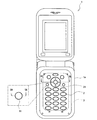
近年、電子機器は多機能化と共にデザインの多様化が生じてきている。特に、ビジネスユースだけでなく、パーソナルユースとして普及してきた図1に示すような携帯電話機1においては、通話機能だけでなくメール機能、撮影機能などのさまざまな機能が登場し多機能化が進行する他、他機種との差別化を図るためのデザインの多様化も進み、このデザインの多様化という観点からも新製品開発に向けた競争が激化している。
In recent years, electronic devices have been diversified in design along with multifunctionalization. In particular, in the
その中にあって、携帯電話機1の表面の一部を形成する押釦スイッチ用キートップ2においても、他機種との差別化を図るデザイン競争が生じてきており、多彩な色の筐体1aに合わせた金属調やパール調、明色などの色調にデザインしたキートップ2が得られてきている。
Among them, the push button
また、キートップ2のデザインを一般消費者が容易に変更できるように、複数のキートップを備えたキーパッド全体を入れ替えることを可能にした技術(特許文献1)も開発されている。
しかしながら、金属調やパール調、明色などの色調にデザインしたキートップ2は、種々の色調を表現できるものであるが、好みの色彩を選択できるにすぎない。また、キートップ自体を代えてしまう特許文献1に記載の発明は、電子機器内に塵埃や水分が入ることもあり機能不良を起こす欠点があった。
However, the
そこで本発明は、さらに改良されたデザインを具現化すべく、斬新な視認性を与えるキートップの獲得を目的としてなされたものである。 Therefore, the present invention has been made for the purpose of acquiring a key top that provides novel visibility in order to realize a further improved design.
また、このデザインの多様化の問題は、キートップだけでなく、文字や記号、さらには模様などが施された、加飾を必要とする樹脂成形体にも生じている問題であるため、さらに改良されたデザイン性と、斬新な視認性を有する加飾が施された樹脂からなる構造体(以下「加飾構造体」という)を得ることをも目的とするものである。 In addition, the problem of diversification of this design is caused not only by key tops but also by resin molded products that require decoration, including letters, symbols, and patterns. Another object of the present invention is to obtain a structure (hereinafter referred to as “decorative structure”) made of a decorated resin having improved design and novel visibility.
この目的を達成するために本発明は、固定偏光層を備える下部体と、下部体とは別体でなり固定偏光層に対して回転可能な可動偏光層を備える上部体とでなる加飾構造体であって、上部体の回転により、可動偏光層と固定偏光層との互いの偏光軸の重なり角度を可変として加飾する加飾構造体を提供する。 In order to achieve this object, the present invention provides a decorative structure comprising a lower body including a fixed polarizing layer and an upper body that is separate from the lower body and includes a movable polarizing layer that is rotatable relative to the fixed polarizing layer. It is a body, and the decoration structure which decorates by making the overlapping angle of the polarization axis of a movable polarizing layer and a fixed polarizing layer variable by rotation of an upper body is provided.
固定偏光層を備える下部体と、下部体とは別体でなり固定偏光層に対して回転可能な可動偏光層を備える上部体とでなる加飾構造体であって、上部体の回転により、可動偏光層と固定偏光層との互いの偏光軸の重なり角度を可変として加飾したため、2つの偏光層の偏光軸の重なり角度の相違によって、光の透過量が変化し、明るく見えたり、暗く見えたり、または、色の濃さが変化して見えたりする加飾が施された加飾構造体が実現できる。 It is a decorative structure composed of a lower body including a fixed polarizing layer and an upper body that is a separate body from the lower body and includes a movable polarizing layer that can rotate with respect to the fixed polarizing layer. Because the overlapping angle of the polarization axis of the movable polarizing layer and the fixed polarizing layer is decorated as variable, the amount of light transmission changes depending on the difference of the overlapping angle of the polarization axes of the two polarizing layers, and it looks bright or dark It is possible to realize a decorated structure that is decorated such that it can be seen or the color intensity changes.
そして、この加飾構造体は、下部体が固定偏光層を備える樹脂成形体であり、上部体が可動偏光層を備える透明樹脂成形体である加飾構造体とすることができる。下部体が、固定偏光層を備える樹脂成形体とし、上部体が、可動偏光層を備える透明樹脂成形体としたため、各偏光層が樹脂成形体で保護されて耐久性、経時安定性に優れた加飾構造体である。 And this decoration structure can be made into the decoration structure whose lower body is a resin molding provided with a fixed polarizing layer, and whose upper body is a transparent resin molding provided with a movable polarization layer. Since the lower body is a resin molded body having a fixed polarizing layer and the upper body is a transparent resin molded body having a movable polarizing layer, each polarizing layer is protected by the resin molded body and has excellent durability and stability over time. It is a decorative structure.
また、この加飾構造体は、可動偏光層を備える上部体が一枚の偏光板である加飾構造体とすることができる。可動偏光層を備える上部体を一枚の偏光板としたため、上部体を簡単に形成することができ、加飾構造体の厚みを薄くすることができる。 Moreover, this decoration structure can be made into the decoration structure whose upper body provided with a movable polarizing layer is one polarizing plate. Since the upper body including the movable polarizing layer is a single polarizing plate, the upper body can be easily formed, and the thickness of the decorative structure can be reduced.
この加飾構造体には、上部体又は下部体の少なくとも何れかに、文字、記号等を表示する表示層を形成し、可動偏光層の回転により偏光軸の重なり角度を固定偏光層の偏光軸に対して可変として、表示層を加飾したものとすることができる。 In this decorative structure, a display layer for displaying characters, symbols, etc. is formed on at least one of the upper body and the lower body, and the overlapping angle of the polarization axes is set by the rotation of the movable polarization layer. As a variable, the display layer can be decorated.
上部体又は下部体の少なくとも何れかに、文字、記号等を表示する表示層を形成し、可動偏光層の回転により偏光軸の重なり角度を固定偏光層の偏光軸に対して可変としたため、表示層を明るくしたり、暗くしたりして視認することができ、また、表示層の背景色を濃くしたり、薄くしたりすることが可能である。 A display layer that displays characters, symbols, etc. is formed on at least one of the upper body and lower body, and the overlapping angle of the polarization axis is variable with respect to the polarization axis of the fixed polarization layer by rotating the movable polarization layer. The layer can be visually recognized by making it brighter or darker, and the background color of the display layer can be made darker or thinner.
また、可動偏光層と固定偏光層とで表示層を形成することができる。可動偏光層と固定偏光層とで表示層を形成したため、表示層自体の明るさや色の濃さを変化させることができ、可動偏光層と固定偏光層との偏光軸の重なり角度の相違によって、表示層が表れたり、消えたりする加飾を施すことができる。そのため、デザイン性に優れるばかりでなく、一つのキーを所定の機能キーとして用いる場合と、用いない場合の表示を変えることができる。 In addition, a display layer can be formed by the movable polarizing layer and the fixed polarizing layer. Since the display layer is formed by the movable polarizing layer and the fixed polarizing layer, the brightness and color density of the display layer itself can be changed, and by the difference in the overlapping angle of the polarization axes of the movable polarizing layer and the fixed polarizing layer, The display layer can appear or disappear. Therefore, not only is it excellent in design, but also the display when one key is used as a predetermined function key and when it is not used can be changed.
また、本発明は、樹脂キートップと可撓性ベースシートとを備える押釦スイッチ用キーシートについて、樹脂キートップを、透明樹脂成形体に可動偏光層を備える上部体と、可撓性ベースシートに固着する樹脂成形体に固定偏光層を備える下部体と、で構成し、上部体が下部体に対して回転することで可動偏光層と固定偏光層の偏光軸の重なり角度が変化することを特徴とする押釦スイッチ用キーシートを提供する。 Further, the present invention relates to a key sheet for a pushbutton switch including a resin key top and a flexible base sheet. The resin key top is a transparent resin molded body, an upper body including a movable polarizing layer, and a flexible base sheet. And a lower body having a fixed polarizing layer on a resin molding to be fixed, and the upper body rotates relative to the lower body, so that the overlapping angle of the polarization axis of the movable polarizing layer and the fixed polarizing layer changes. A key sheet for a push button switch is provided.
樹脂キートップと可撓性ベースシートとを備える押釦スイッチ用キーシートについて、樹脂キートップを、透明樹脂成形体に可動偏光層を備える上部体と、可撓性ベースシートに固着する樹脂成形体に固定偏光層を備える下部体と、で構成し、上部体が下部体に対して回転することで可動偏光層と固定偏光層の偏光軸の重なり角度が変化することとしたため、2つの偏光層の偏光軸の重なり角度の相違によって、光の透過量が変化し、明るく見えたり、暗く見えたり、または、色の濃さが変化して見えたりする加飾が施されたデザイン性に優れた押釦スイッチ用キーシートとすることができる。 For a key sheet for a pushbutton switch including a resin key top and a flexible base sheet, the resin key top is divided into an upper body including a movable polarizing layer on a transparent resin molded body, and a resin molded body fixed to the flexible base sheet. A lower body having a fixed polarizing layer, and the upper body rotates with respect to the lower body, so that the overlapping angle of the polarization axes of the movable polarizing layer and the fixed polarizing layer changes. A pushbutton with excellent design that has a decoration that makes the light transmission change depending on the polarization axis overlap angle, looks bright, looks dark, or changes the color density. It can be used as a key sheet for a switch.
この押釦スイッチ用キーシートには、上部体と下部体との境界に、上部体の回転をし易くする滑層を設けることができる。上部体と下部体との境界に、上部体の回転をし易くする滑層を設ければ、上部体が下部体に対してスムーズに回転し、操作性が良好な押釦スイッチ用キーシートとなる。 The key sheet for the push button switch can be provided with a sliding layer that facilitates the rotation of the upper body at the boundary between the upper body and the lower body. If a slipping layer that facilitates rotation of the upper body is provided at the boundary between the upper body and the lower body, the upper body rotates smoothly with respect to the lower body, resulting in a key sheet for a pushbutton switch with good operability. .
また、この押釦スイッチ用キーシートには、上部体が下部体に対する所定位置で止まる回転規制手段を上部体に設けたものとすることができる。上部体が下部体に対する所定位置で止まる回転規制手段を上部体に設けたため、可動偏光層と固定偏光層との偏光軸の重なり角度が、所定の角度となる位置で可動偏光層を止めることができ、明度や色調について所定の視認性を与えたり、特定のキーとして表示したり、しなかったりといった加飾の程度を予め定めた位置に容易に上部体を止めることができる。 Further, this push button switch key sheet may be provided with a rotation restricting means for stopping the upper body at a predetermined position relative to the lower body. Since the upper body is provided with a rotation restricting means that stops the upper body at a predetermined position with respect to the lower body, the movable polarizing layer can be stopped at a position where the overlapping angle of the polarization axes of the movable polarizing layer and the fixed polarizing layer becomes a predetermined angle. It is possible to easily stop the upper body at a position where a degree of decoration such as giving predetermined visibility for brightness and color tone, displaying as a specific key, or not, is predetermined.
上記回転規制手段については、上部体とは別体である機器に設けた突起と凹部の何れか一方に対して係合する突起と凹部の何れか他方を回転規制手段とすることができる。回転規制手段を突起または凹部の何れか一方として形成すれば、上部体とは別体である機器の筐体に設けた突起または凹部の何れか他方に対して係合させることとでき、上部体を下部体に対する所定位置で止めることが可能となる。また、この回転規制手段については磁石とすることもできる。磁石として形成すれば上部体とは別体である機器の筐体に設けた磁石と互いに引き合うように配置して、磁石の吸引力で強く引かれる位置で上部体を止めることが可能である。このように、回転規制手段が、突起または凹部であるか、磁石であれば、その形成も容易であるし、回転と停止の間の移行も容易に行うことができる。 As for the rotation restricting means, any one of the protrusion and the recessed portion that engages with either the protrusion or the recessed portion provided in the device separate from the upper body can be used as the rotation restricting means. If the rotation restricting means is formed as either one of the protrusion or the recess, it can be engaged with either the protrusion or the recess provided on the housing of the device which is separate from the upper body. Can be stopped at a predetermined position relative to the lower body. The rotation restricting means may be a magnet. If it is formed as a magnet, it can be arranged so as to be attracted to a magnet provided in a housing of the device which is separate from the upper body, and the upper body can be stopped at a position where it is strongly attracted by the attractive force of the magnet. Thus, if the rotation restricting means is a protrusion or a recess, or a magnet, its formation is easy, and transition between rotation and stop can be easily performed.
そして、本発明では、下部体を構成する樹脂成形体を透明な樹脂成形体とすることができる。透明な樹脂成形体としたため、この樹脂成形体の裏面側(ベースシート側)に固定偏光層を設けても加飾を得ることができる。透明な樹脂成形体の裏面に固定偏光層を形成すれば、固定偏光層が透明な樹脂成形体で保護されて、上部体との摩擦による固定偏光層の影響を問題にする必要がなくなる利点がある。 And in this invention, the resin molding which comprises a lower body can be made into a transparent resin molding. Since it was set as the transparent resin molding, even if it provides a fixed polarizing layer in the back surface side (base sheet side) of this resin molding, decoration can be obtained. If the fixed polarizing layer is formed on the back surface of the transparent resin molded body, the fixed polarizing layer is protected by the transparent resin molded body, and there is no need to consider the influence of the fixed polarizing layer due to friction with the upper body. is there.
本発明の加飾構造体や押釦スイッチ用キーシートによれば、キートップを含む加飾構造体に全く新しい視認性、デザインを与えることができ、特に、バラエティー性に対する要求の高いパーソナルユース向けの材料として、またその材料を用いた完成品として好適に用いることができる。 According to the decorative structure and the key sheet for the pushbutton switch of the present invention, it is possible to give a completely new visibility and design to the decorative structure including the key top, especially for personal use with high demand for variety. It can be suitably used as a material and as a finished product using the material.
本発明の加飾構造体の実施形態として、携帯電話機1において用いられるキートップ、および、このキートップが可撓性のベースシートと一体になったキーシートについて図面を参照して説明する。なお、添付の図において、構成材の厚さや長さは、説明の便宜や見易さのため実際の縮尺に基づくものではない。また、従来技術と共通する構成、各実施形態で共通する構成(層厚を含む)や製造方法については、重複説明を省略する。
As an embodiment of the decorative structure of the present invention, a key top used in a
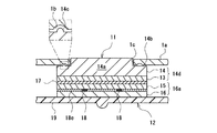
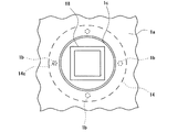
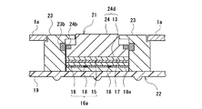
第1実施形態; 第1実施形態における本発明の加飾構造体は、携帯電話機1で用いる押釦スイッチ用キートップ11として実現したものである。図2には、このキートップ11を備えたキーシート12と筐体1aの一部拡大断面を、図3には、キートップ11を配置した携帯電話機1の一部平面をそれぞれ示す。このキートップ11は、可動偏光層13を設けた上部透明樹脂成形体14でなる上部体14dと、該上部体14dとは別体であり固定偏光層15を設けた下部樹脂成形体16でなる下部体16aと、が積層したものである。可動偏光層13と固定偏光層15との境界面には滑層17を有し、また、文字や記号などを表す表示層18と表示層18の周囲を目地埋めする目地埋め層18eを下部樹脂成形体16の表面に有している。このキートップ11は、下部体16aがシリコーンゴムなどのゴム状弾性体でなるベースシート19と図外の接着剤で固着されてキーシート12を形成している。キーシート12は、キートップ11を指で押圧すると、ベースシート19が弾性変形し、その押圧操作方向に配置する金属皿ばね(図示せず)を押圧して、プリント基板上の固定接点(図示せず)が導通するようになっている。
1st Embodiment ; The decoration structure of this invention in 1st Embodiment is implement | achieved as the
このような構成からなるキーシート12は、キートップ11を構成する上部体14dが筐体1aの裏面や、筐体1aに設けられた貫通孔1cの内周面に臨むような位置で、滑層17を介して下部体16aの上に載置されている。そのため、上部体14dに形成された抜止め部14bが筐体1aの裏面に当たって外部には外れず、また貫通孔1cの内周面に当たって、押圧操作方向に対する垂直方向にずれ込まない位置に保持されながら、下部体16aの上を自由に回転できるようになっている。また、抜止め部14bとなる上部樹脂成形体14の上面には、携帯電話機1の筐体1aに等間隔に4箇所設けられた凹部1bと係合しあう突起14cが1箇所形成されている。凹部1bと突起14cは、それぞれ筐体1aまたはキートップ11の回転規制手段となり、下部体16aに対する上部体14dの回転位置を確認し、回転規制手段どうしが向き合う位置で回転を安定的に止めることができるようになっている。
The
キーシート12を構成する各層の材質等を詳しく説明すると、上部透明樹脂成形体14は、ポリカーボネート樹脂やポリメチルメタクリレート樹脂、ポリアクリロニトリルブタジエンスチレン樹脂、アクリロニトリルスチレン樹脂、ポリアミド樹脂、ポリウレタン樹脂、ポリスチレン樹脂、ポリエステル樹脂、ポリプロピレン樹脂などの透明な樹脂でなり、予め押出成形、射出成形などによって円柱状の本体部14aとその外周に抜止め部14bを有する凸状に成形したものである。また、上部透明樹脂成形体14の裏面全体に設けられた可動偏光層13は、偏光板から形成されている。偏光板は光振動の特定の成分のみを透過させるため、2枚の偏光板を重ねた場合に、互いの偏光板の偏光軸が同方向を向く場合は光が通るが、偏光軸が直交する場合に光が通らないという性質を有するものである。この偏光板には、スモーク偏光板や、ブルー偏光板などの各種色彩を有する偏光板を用いることができる。また、偏光板には板状のものだけでなく、フィルム状の薄膜のものをも含む。上部透明樹脂成形体14への可動偏光層13の形成は、上部透明樹脂成形体14に透明な接着剤で偏光板を固着したり、上部透明樹脂成形体14を成形する際の金型内に偏光板を予め配置しておき、偏光板と上部透明樹脂成形体14を一体成形することでも可能である。
The material of each layer constituting the
一方、下部樹脂成形体16は、上部透明樹脂成形体14と外周の大きさが同程度となる円柱状に形成したものであり、上部透明樹脂成形体14と同じ材料、方法で成形することができる。下部樹脂成形体16の表面に設けた、文字や記号などを表す表示層18や、その周囲を目地埋めする目地埋め層18eは、パッド印刷やスクリーン印刷などで形成し、図3では、表示層18は“□”印を示している。また、下部樹脂成形体16の上層に設けた固定偏光層15も偏光板からなり、表示層18を有する下部樹脂成形体16の表面に接着剤などで固着したものである。固定偏光層15も可動偏光層13と同じ材料から得ることができる。滑層17は、シリコーン系やパラフィン系などの滑剤を可動偏光層13または固定偏光層15上に塗布して形成したものである。
On the other hand, the lower resin molded
次に、携帯電話機1に組み込まれたキーシート12の作用について説明する。
Next, the operation of the
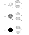
キーシート12は、キートップ11への押圧操作によって、入力キーとして機能することはもちろんであるが、表示層18の視認性を操作者が意図的に変化させることができるキーシートである。上部体14dを貫通孔1c内で回転させると、下部樹脂成形体16に固着した固定偏光層15に対して、上部透明樹脂成形体14に固着した可動偏光層13が回転し、可動偏光層13と固定偏光層15の互いの偏光軸の重なり角度が変化する。そのため、可動偏光層13と固定偏光層15を通って視認される表示層18の明るさが変化する。これを模式図を用いて説明すれば、図4に示すように、可動偏光層13と固定偏光層15の偏光軸が同方向を向く(A)の場合に表示層18は明るく見える。しかし、可動偏光層13が(A)の場合から45°回転した(B)になると、表示層18はやや暗く視認される。さらに、可動偏光層13が回転して、可動偏光層13と固定偏光層15との偏光軸が直交し、その重なり角度が90°になると、キートップ11の表面が暗くなって表示層18が視認できなくなる。なお、図4における可動偏光層13、固定偏光層15において示した線は、それぞれ偏光軸を表す。
The
上部透明樹脂成形体14を回転させ、キートップ11の抜止め部14bに形成された突起14cが、携帯電話機1の筐体1aに形成された凹部1bに当たって重なると、上部透明樹脂成形体14の回転を止め、安定的に上部体14dをその位置に止めておくことができる。可動偏光層13と固定偏光層15にはスモーク偏光板を用い、突起14cと凹部1bとが重なる位置で、可動偏光層13と固定偏光層15との互いの偏光軸の重なり角度を0°としておけば、光が両偏光層13,15で遮られることなく、表示層18として表れる形状を明るく視認することができる。一方、重なり角度を90°としておけば、光が両偏光層13,15で遮られ、表示層18として表れる形状を視認することができなくなる。
When the upper transparent resin molded
したがって、可動偏光層13と固定偏光層15の偏光軸の重なり角度を0°、90°とした位置に回転規制手段を設けておけば、上部透明樹脂成形体14を任意に回転させても、明るく視認できる位置と視認できない位置を回転中に容易に決定でき、この位置で下部体16aに対し安定的に上部体14dを止めておくことができる。さらに、45°の位置に回転規制手段を設けておけば、これらの中間程度の明るさとして視認することができ視認性の異なる3段階の位置を容易に選択することができる。
Therefore, if the rotation restricting means is provided at a position where the overlapping angle of the polarization axes of the movable
本実施形態ではキートップ11の横断面として表れる面全体に、可動偏光層13と固定偏光層15を形成しているため、キートップ11を外部から視認すると、キートップ11の表面全体の明るさや色を変化させることができる。すなわち、可動偏光層13と固定偏光層15の双方にスモーク偏光板を用いれば、明るくなったり、暗くなったりして、表示層18が明瞭に視認できたり、視認できなかったりといった変化を楽しむことができる。また、スモーク偏光板とブルー偏光板を用いれば、明るく無色の中に表示層18が見える状態から、周囲の青みの程度が徐々に増し、濃い青色の中に表示層18が見える状態までを楽しむことができる。したがって、このキーシート12を用いた携帯電話機1では、操作者の使用時の雰囲気、環境、心持ちに応じて表示層18の表示状態を意図的に変えることができる。
In this embodiment, since the movable
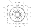
第2実施形態; 第2実施形態における本発明の加飾構造体は、携帯電話機1で用いるキートップ21として実現したものである。図5には、このキートップ21を備えたキーシート22と筐体1aの一部拡大断面を、図6にはその平面を示す。図5で示す多方向キートップは、中央入力キーに該当するキートップ21と、このキートップ21の周囲にある円環キー23とで構成されている。キートップ21は、第1実施形態で示したキートップ11と同じ層構成を有するが、回転規制手段として突起14cの代わりに磁石24bを設けた点がキートップ11と異なるところである。すなわち、キートップ21の上部透明樹脂成形体24に設けた磁石24bと円環キー23に設けた磁石23bが互いに引き合うような向きに、それぞれの磁石24b,23bを配置することで、キートップ21に設けられた磁石24bと円環キー23に設けられた磁石23bが向き合う位置で上部体24aが止まるようになっている。
Second Embodiment ; The decorative structure of the present invention in the second embodiment is realized as the key top 21 used in the
キートップ21を備えたキーシート22も、中央入力キーに該当するキートップ21を回転させることで、表示層18の視認性を変化させることができる。また、回転規制手段を上部樹脂成形体24の周囲に適当な数だけ設けて、その回転規制手段において、上部樹脂成形体24を止め易くすることができる。
The
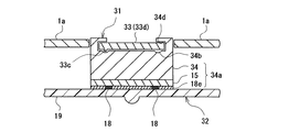
第3実施形態; 第3実施形態によるキートップ31は、第1実施形態におけるキートップ11のように、透明樹脂成形体34が上部透明樹脂成形体14と下部樹脂成形体16とに分断されたものではなく、図7で示すように、一つの透明樹脂成形体34に固定偏光層15を固着して下部体34aを形成する一方、透明樹脂成形体34には可動偏光層33を回転自在に保持する挿入溝34dを設け、その中に可動偏光層33単体でなる上部体33dを嵌めこんだものである。したがって、可動偏光層33となる偏光板は透明樹脂成形体34とは固着しておらず、固定偏光層15を有する下部体34aに対して回転可能である。
Third Embodiment : The key top 31 according to the third embodiment has a transparent resin molded
本実施形態における可動偏光層33として用いる偏光板は、透明樹脂成形体34の形成後に、その挿入溝34dに装着する必要があるため、挿入溝34dに入りこむだけの柔軟性を有する必要がある。
Since the polarizing plate used as the movable
本実施形態では、可動偏光層33の端に突起33cを、透明樹脂成形体34に凹部34bを設けて、回転規制手段を形成している。
In this embodiment, a
キートップ31を備えたキーシート32も、可動偏光層33となる偏光板を回転させることで、表示層18の視認性を変化させることができる。
The
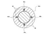
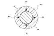
第4実施形態; 第4実施形態によるキートップ41は、図8で示すように、第2実施形態で示したいわゆる多方向キーのうち、円環キー41を加飾構造体としたものである。円環キー41は、入力位置を示す箇所に図1で示す三角形状の表示層48が形成されている。
Fourth Embodiment : As shown in FIG. 8, the key top 41 according to the fourth embodiment is a so-called multidirectional key shown in the second embodiment in which the
キートップ41の層構成が第1実施形態で示したキートップ11と異なるのは、まず、偏光板で表示層48を形成している点にある。図9、図10にこの多方向キーの図8におけるSC−SC線断面図とSD−SD線断面図を示すが、可動偏光層43は、図9で示すように上部透明樹脂成形体44の裏面に三角形状をした4片のスモーク偏光板を、全ての偏光板の偏光軸が同方向を向くように固着して、4つの可動偏光層43a,43b,43c,43dを形成している。偏光板が配置されてない部分は透明な樹脂で目地埋めされた目地埋め層43eとなっている。
The layer structure of the key top 41 is different from the key top 11 shown in the first embodiment in that the
固定偏光層45は、図10で示すように、下部樹脂成形体46の上面に三角形状をした4片のスモーク偏光板からなる4つの固定偏光層45a,45b,45c,45dが形成されている。固定偏光層45の偏光軸の向きは、上下位置に配置された固定偏光層45a,45cでは、図中矢印で示すように上下方向であり、左右位置に配置された固定偏光層45b,45dでは左右方向である。固定偏光層45の偏光板が配置されてない部分も透明な樹脂で目地埋めされ、目地埋め層45eとなっている。
As shown in FIG. 10, the fixed
このように、これまでの実施形態によるキートップ11,21,31では偏光層とは別に表示層18を形成していたのに対し、本実施形態のキートップ41では偏光層を表示層48としている。可動偏光層43と固定偏光層45の境界面に滑層47が形成されているのは他の実施形態におけるキートップ11,21,31と同様である。
As described above, in the key tops 11, 21, and 31 according to the previous embodiments, the
また、キートップ41の抜止め部44bに突起44cが、筐体1aの裏面に凹部1bがそれぞれ形成されており、可動偏光層43と固定偏光層45とが重なる位置で突起44cと凹部1bが重なるように、回転規制手段が設けられている。
A
このような構成からなるキートップ41は、例えば、可動偏光層43と固定偏光層45とが重なった際、固定偏光層45aに対して可動偏光層43aが重なる場合には、互いの偏光軸が同じ向きを向き、上下にある表示層48は光を通して視認されない。一方、この場合には固定偏光層45bと可動偏光層43bとが重なるため、互いの偏光軸が直交し、左右にある表示層48は光を遮断して三角形状が視認される。
For example, when the movable
これに対して、固定偏光層45aに対して可動偏光層43dが重なる場合には、互いの偏光軸が直交し、上下にある表示層48は光を遮断して三角形状が視認される。一方、この場合には固定偏光層45bと可動偏光層43aとが重なるため、互いの偏光軸が同じ向きを向き、左右にある表示層48は光を透過して三角形状が視認されない。従ってキートップ41の表示層48を、上下方向のキーのみを視認される場合と、左右方向のキーのみを視認される場合とを区別することができるため、上下方向を入力キーとして機能させる場合と、左右方向を入力キーとして機能させる場合とに対応した表示を行うことが可能となる。
On the other hand, when the movable
この実施形態の変形例として、4つの固定偏光層45a,45b,45c,45dを全て同じ向きに偏光軸が向くように配置すれば、キートップ41の回転によって、4つの三角形状が全て視認される場合と、4つの三角形状が全て視認されない場合とに分かれるキートップ41とすることができる。
As a modification of this embodiment, if the four fixed
上記実施形態は何れも本発明の一例を示したものに過ぎず、表示層18,48の視認性を変化させることができるという本発明の目的を達成できる限度において適度の変更が可能である。 Each of the above embodiments is merely an example of the present invention, and appropriate changes can be made as long as the object of the present invention that the visibility of the display layers 18 and 48 can be changed can be achieved.
例えば、全てのキートップ11,21,31,41形状や、一般的なキーか多方向キーかといった種類は上記の例に限定されるものではない。また、その層構成も例えば滑層17,47は設けないことも可能であるし、表示層18,48の層構成中における位置も変更可能である。また、回転規制手段を設ける位置や数、回転規制手段の形状についても、例えば、凹部1bをキートップ11,31側に設けるなどの適宜変更が可能である。
For example, the shape of all the key tops 11, 21, 31, 41 and whether they are general keys or multi-directional keys are not limited to the above example. In addition, for example, the sliding
また、ベースシート19を透光性にするなどして、キーシート12,22,32,42の下部から発光させてキートップ11,21,31,41を照光させる照光式キートップとすることができ、さらに、キートップ11,21,31,41以外の加飾構造体に対して適用することができる。
Further, by making the
1 携帯電話機
1a 筐体
1b 凹部
1c 貫通孔
2,11,21,31,41 押釦スイッチ用キートップ(キートップ)
3,12,22,32,42 キーシート
13,33 可動偏光層
33c 突起(回転規制手段)
14,24,34 上部透明樹脂成形体
14a 本体部
14b,44b 抜止め部
14c,44c 突起(回転規制手段)
14d,24d,33d,44d 上部体
24c 磁石
34b 凹部
34d 挿入溝
15 固定偏光層
16 下部樹脂成形体
16a,34a,46a 下部体
17 滑層
18,48 表示層
18e,48e 目地埋め層
19 ベースシート
23 円環キー
23b 磁石
DESCRIPTION OF
3, 12, 22, 32, 42
14, 24, 34 Upper
14d, 24d, 33d, 44d Upper
Claims (12)
上部体の回転により、可動偏光層と固定偏光層との互いの偏光軸の重なり角度を可変として加飾する加飾構造体。 A decorative structure comprising a lower body including a fixed polarizing layer and an upper body including a movable polarizing layer that is separate from the lower body and is rotatable with respect to the fixed polarizing layer,
A decoration structure that decorates the movable polarizing layer and the fixed polarizing layer by changing the overlapping angle of the polarization axes by rotating the upper body.
樹脂キートップを、透明樹脂成形体に可動偏光層を備える上部体と、可撓性ベースシートに固着する樹脂成形体に固定偏光層を備える下部体と、で構成し、上部体が下部体に対して回転することで可動偏光層と固定偏光層の偏光軸の重なり角度が変化することを特徴とする押釦スイッチ用キーシート。 In a key sheet for a push button switch comprising a resin key top and a flexible base sheet,
The resin key top is composed of an upper body having a movable polarizing layer on a transparent resin molded body, and a lower body having a fixed polarizing layer on a resin molded body fixed to a flexible base sheet. A key sheet for a pushbutton switch, characterized in that the rotation angle of the polarization axis of the movable polarizing layer and the fixed polarizing layer changes by rotating relative to the key sheet.
12. The key sheet for a pushbutton switch according to claim 11, wherein the resin key top is an illuminated resin key top.
Priority Applications (1)
| Application Number | Priority Date | Filing Date | Title |
|---|---|---|---|
| JP2004109533A JP4398770B2 (en) | 2004-04-01 | 2004-04-01 | Decorative structure and key sheet for pushbutton switch |
Applications Claiming Priority (1)
| Application Number | Priority Date | Filing Date | Title |
|---|---|---|---|
| JP2004109533A JP4398770B2 (en) | 2004-04-01 | 2004-04-01 | Decorative structure and key sheet for pushbutton switch |
Publications (2)
| Publication Number | Publication Date |
|---|---|
| JP2005293380A true JP2005293380A (en) | 2005-10-20 |
| JP4398770B2 JP4398770B2 (en) | 2010-01-13 |
Family
ID=35326218
Family Applications (1)
| Application Number | Title | Priority Date | Filing Date |
|---|---|---|---|
| JP2004109533A Expired - Fee Related JP4398770B2 (en) | 2004-04-01 | 2004-04-01 | Decorative structure and key sheet for pushbutton switch |
Country Status (1)
| Country | Link |
|---|---|
| JP (1) | JP4398770B2 (en) |
Cited By (3)
| Publication number | Priority date | Publication date | Assignee | Title |
|---|---|---|---|---|
| JP2009218127A (en) * | 2008-03-12 | 2009-09-24 | Casio Hitachi Mobile Communications Co Ltd | Key input device, and electronic apparatus |
| CN110312015A (en) * | 2019-06-30 | 2019-10-08 | Oppo广东移动通信有限公司 | Electronic device and electronic device control method |
| CN110401751A (en) * | 2019-07-31 | 2019-11-01 | Oppo广东移动通信有限公司 | Electronic device and electronic device control method |
-
2004
- 2004-04-01 JP JP2004109533A patent/JP4398770B2/en not_active Expired - Fee Related
Cited By (3)
| Publication number | Priority date | Publication date | Assignee | Title |
|---|---|---|---|---|
| JP2009218127A (en) * | 2008-03-12 | 2009-09-24 | Casio Hitachi Mobile Communications Co Ltd | Key input device, and electronic apparatus |
| CN110312015A (en) * | 2019-06-30 | 2019-10-08 | Oppo广东移动通信有限公司 | Electronic device and electronic device control method |
| CN110401751A (en) * | 2019-07-31 | 2019-11-01 | Oppo广东移动通信有限公司 | Electronic device and electronic device control method |
Also Published As
| Publication number | Publication date |
|---|---|
| JP4398770B2 (en) | 2010-01-13 |
Similar Documents
| Publication | Publication Date | Title |
|---|---|---|
| EP1952544B1 (en) | Waterproof in-mould foil (imf) cover with two layers for a portable electronic device | |
| JP4621199B2 (en) | Key unit with reinforcing plate | |
| JP2008041431A (en) | KEY SHEET, KEY UNIT HAVING THE SAME AND KEY SHEET MANUFACTURING METHOD | |
| CN101779176A (en) | Illuminated keyboard and light guide for graphic symbols and method | |
| EP3488456B1 (en) | Equipment with keys having trim and illumination | |
| CN1732670A (en) | Multifunction keypad | |
| CN100534102C (en) | Film layer, assembly and method for altering the appearance of a mobile station | |
| US5934450A (en) | Electronic device with holographic keypad | |
| CN101802951A (en) | Display device and key device | |
| TW200840700A (en) | Manufacturing method for electronic device's panel and structure thereof | |
| US7982715B2 (en) | User input for an electronic device | |
| JP4398770B2 (en) | Decorative structure and key sheet for pushbutton switch | |
| JP2004139847A (en) | Push-button switch member | |
| US20100245133A1 (en) | Key sheet | |
| WO2005117047A1 (en) | Key unit with casing | |
| JP4113784B2 (en) | Pushbutton switch member and manufacturing method thereof | |
| CN100576395C (en) | Multilayer color light guide structure, use method thereof and key module with structure | |
| CN2912144Y (en) | Rocker type dustproof remote controller of TV set | |
| JPH08235957A (en) | Transparent push button assembly body and its production | |
| CN100490038C (en) | Key and keyboard | |
| KR100588263B1 (en) | Stereo keypad and its manufacturing method | |
| JP2007213839A (en) | Illumination type decorated molding, and illumination type key sheet | |
| JP4698336B2 (en) | Key sheet with key top | |
| JPH0997531A (en) | Rubber contact switch | |
| JP4724011B2 (en) | Decorative molded body and key sheet |
Legal Events
| Date | Code | Title | Description |
|---|---|---|---|
| A621 | Written request for application examination |
Free format text: JAPANESE INTERMEDIATE CODE: A621 Effective date: 20070328 |
|
| A977 | Report on retrieval |
Free format text: JAPANESE INTERMEDIATE CODE: A971007 Effective date: 20090316 |
|
| A131 | Notification of reasons for refusal |
Free format text: JAPANESE INTERMEDIATE CODE: A131 Effective date: 20090331 |
|
| A521 | Written amendment |
Free format text: JAPANESE INTERMEDIATE CODE: A523 Effective date: 20090529 |
|
| A131 | Notification of reasons for refusal |
Free format text: JAPANESE INTERMEDIATE CODE: A131 Effective date: 20090717 |
|
| A521 | Written amendment |
Free format text: JAPANESE INTERMEDIATE CODE: A523 Effective date: 20090903 |
|
| TRDD | Decision of grant or rejection written | ||
| A01 | Written decision to grant a patent or to grant a registration (utility model) |
Free format text: JAPANESE INTERMEDIATE CODE: A01 Effective date: 20090929 |
|
| A01 | Written decision to grant a patent or to grant a registration (utility model) |
Free format text: JAPANESE INTERMEDIATE CODE: A01 |
|
| A61 | First payment of annual fees (during grant procedure) |
Free format text: JAPANESE INTERMEDIATE CODE: A61 Effective date: 20091023 |
|
| FPAY | Renewal fee payment (event date is renewal date of database) |
Free format text: PAYMENT UNTIL: 20121030 Year of fee payment: 3 |
|
| R150 | Certificate of patent or registration of utility model |
Free format text: JAPANESE INTERMEDIATE CODE: R150 |
|
| LAPS | Cancellation because of no payment of annual fees |