JP2005293350A - 3D object verification device - Google Patents
3D object verification device Download PDFInfo
- Publication number
- JP2005293350A JP2005293350A JP2004108990A JP2004108990A JP2005293350A JP 2005293350 A JP2005293350 A JP 2005293350A JP 2004108990 A JP2004108990 A JP 2004108990A JP 2004108990 A JP2004108990 A JP 2004108990A JP 2005293350 A JP2005293350 A JP 2005293350A
- Authority
- JP
- Japan
- Prior art keywords
- data
- dimensional
- collation
- resolution
- selection
- Prior art date
- Legal status (The legal status is an assumption and is not a legal conclusion. Google has not performed a legal analysis and makes no representation as to the accuracy of the status listed.)
- Granted
Links
Images
Landscapes
- Length Measuring Devices By Optical Means (AREA)
- Image Processing (AREA)
- Image Analysis (AREA)
Abstract
【課題】 実用性の高い照合性能を実現するために、センサによる計測誤差の影響を低減しながら、高速かつ高精度の照合を可能とする3次元物体照合装置を提供すること。
【解決手段】 3次元データの各計測点について計測誤差を推定する誤差特性評価手段14と、3次元データから1以上のデータ領域を切り出し、データ分散が閾値よりも大きなデータ領域を初期候補として選定する特徴部分抽出手段16と、データ領域又は前記データ領域同士の組合せについて推定処理時間と推定照合精度を計算する処理時間・精度評価手段18と、初期候補から目標処理時間と目標照合精度を達成するデータ領域又はデータ領域同士の組合せを選定する照合データ領域選定手段10とを備え、3次元データ照合手段が、照合データ領域選定手段10の選定したデータ領域又はデータ領域同士の組合せについて標準3次元データとの照合を行う。
【選択図】図1
PROBLEM TO BE SOLVED: To provide a three-dimensional object matching device capable of high-speed and high-precision matching while reducing the influence of a measurement error by a sensor in order to realize highly practical matching performance.
SOLUTION: An error characteristic evaluation unit 14 for estimating a measurement error at each measurement point of three-dimensional data, and one or more data regions are cut out from the three-dimensional data, and a data region whose data variance is larger than a threshold value is selected as an initial candidate. And the target processing time and target collation accuracy are achieved from the initial candidates. A collation data area selecting means for selecting a data area or a combination of data areas, and the three-dimensional data collating means is a standard three-dimensional data for the data area selected by the collation data area selecting means or a combination of the data areas. Is checked.
[Selection] Figure 1
Description
本件発明は、3次元物体の計測データを既知モデルを対比することにより位置姿勢推定や物体識別を行う3次元物体照合装置に関し、特に、計測誤差を考慮して高速かつ高精度の位置姿勢推定や物体識別を可能とする3次元物体照合装置に関する。 The present invention relates to a three-dimensional object collation apparatus that performs position / orientation estimation and object identification by comparing measurement data of a three-dimensional object with a known model, and in particular, provides high-speed and high-accuracy position / orientation estimation in consideration of measurement errors. The present invention relates to a three-dimensional object matching apparatus that enables object identification.
近年、センサによって計測した3次元データ(レンジデータ又は距離画像)に基づいて物体の位置姿勢推定や物体識別を行う3次元物体照合技術が注目されている。この3次元データを、既知の物体モデルと対比することにより位置姿勢推定や物体識別を行うことができる。3次元物体照合技術には様々なものがある。 In recent years, attention has been paid to a three-dimensional object matching technique for estimating the position and orientation of an object and identifying an object based on three-dimensional data (range data or distance image) measured by a sensor. By comparing this three-dimensional data with a known object model, position and orientation estimation and object identification can be performed. There are various three-dimensional object matching techniques.
例えば、特開平6−109451号公報(特許文献1)では、計測したレンジデータを物体モデルと照合するために、事前に物体モデルの見え方に関するデータ表(3次元アスペクト表)を生成しておき、レンジデータから抽出した3次元特徴量によって3次元アスペクト表を参照して視方向を決定し、その視方向と既知の視点と物体モデルとから3次元物体の姿勢を推定する。また、特開平10−124677号公報(特許文献2)では、計測したレンジデータから平面と円筒面を検出し、この検出結果と基準配置モデルを参照して姿勢候補を選択する。姿勢候補の選択には、一般化ハフ変換等の多数決原理を用いている。しかしながら、これらの3次元物体照合技術では、予め生成したアスペクト表や姿勢候補の中から最もよく合致する姿勢を選択するため、高精度の姿勢推定を行うことは困難である。 For example, in Japanese Patent Laid-Open No. 6-109451 (Patent Document 1), in order to collate the measured range data with the object model, a data table (three-dimensional aspect table) relating to how the object model looks is generated in advance. The viewing direction is determined by referring to the three-dimensional aspect table based on the three-dimensional feature amount extracted from the range data, and the posture of the three-dimensional object is estimated from the viewing direction, the known viewpoint, and the object model. In Japanese Patent Laid-Open No. 10-124677 (Patent Document 2), a plane and a cylindrical surface are detected from the measured range data, and a posture candidate is selected with reference to the detection result and a reference arrangement model. A majority rule such as generalized Hough transform is used to select the posture candidate. However, with these three-dimensional object matching techniques, it is difficult to perform highly accurate posture estimation because the best matching posture is selected from pre-generated aspect tables and posture candidates.
一方、Besl等の提唱するICPアルゴリズム(非特許文献1)では、レンジデータから特徴量を抽出する代わりに、ともに点群として表されるレンジデータと物体モデルデータの間で、一方の形状データの各点から他方の形状データの最も近い点までの距離の2乗和を最小化することにより、2つの形状データが最も良く重なるような座標変換を得る。また清水等(非特許文献2)は、ICPアルゴリズムにおいてセンサの視線方向に生じる計測誤差を考慮して、計測誤差の生じる範囲を誤差の標準偏差σとして規定し、σに応じた適合度を与えることにより計測誤差の影響を考慮した照合を行っている。 On the other hand, in the ICP algorithm proposed by Besl et al. (Non-Patent Document 1), instead of extracting feature values from range data, one of the shape data between the range data and the object model data, both represented as point clouds, is used. By minimizing the sum of squares of the distance from each point to the closest point of the other shape data, a coordinate transformation that best overlaps the two shape data is obtained. Shimizu et al. (Non-Patent Document 2) takes into account the measurement error that occurs in the direction of the line of sight of the sensor in the ICP algorithm, defines the range in which the measurement error occurs as the standard deviation σ of the error, and gives the degree of conformance according to σ Therefore, collation considering the influence of measurement error is performed.
ICPアルゴリズムのように点群同士の照合を行えば照合精度を高めることができるが、大量のデータ点数を照合に用いる必要があり、高速の照合が行えないという問題が生じる。また、照合精度を高めるためにはセンサによって生じる計測誤差の影響も考慮する必要があるが、清水等(非特許文献2)の提案する方法では単一の視線方向に生じる計測誤差しか考慮されておらず、物体の形状によっては十分な照合精度を得ることができない。 If the point groups are collated as in the ICP algorithm, the collation accuracy can be increased, but a large number of data points need to be used for collation, resulting in a problem that high-speed collation cannot be performed. Moreover, in order to improve the collation accuracy, it is necessary to consider the influence of the measurement error caused by the sensor. However, the method proposed by Shimizu et al. In other words, sufficient matching accuracy cannot be obtained depending on the shape of the object.
そこで本件発明は、実用性の高い照合性能を実現するために、センサによる計測誤差の影響を低減しながら、高速かつ高精度の照合を可能とする3次元物体照合装置を提供することを目的とする。 Accordingly, the present invention has an object to provide a three-dimensional object matching device that enables high-speed and high-precision matching while reducing the influence of measurement errors caused by sensors in order to realize highly practical matching performance. To do.
上記目的を達成するために、本件発明に係る3次元物体照合装置は、物体の立体形状を計測して3次元データを得る3次元データ取得手段と、取得した3次元データを蓄積する3次元データ蓄積手段と、取得した3次元データと参照すべき標準3次元データとの照合を行う3次元データ照合手段とを備えた3次元物体照合装置であって、さらに、前記3次元データの各計測点について計測誤差を推定する誤差特性評価手段と、前記3次元データから1以上のデータ領域を切り出し、所定の形状特徴値が閾値よりも大きなデータ領域を初期候補として選定する特徴部分抽出手段と、前記データ領域又は前記データ領域同士の組合せについて推定処理時間と推定照合精度を計算する処理時間・精度評価手段と、前記初期候補から、目標処理時間と目標照合精度を達成するデータ領域又はデータ領域同士の組合せを選定する照合データ領域選定手段とを備え、前記3次元データ照合手段が、前記照合データ領域選定手段の選定したデータ領域又はデータ領域同士の組合せについて標準3次元データとの照合を行うことを特徴とする。 In order to achieve the above object, a three-dimensional object matching device according to the present invention includes a three-dimensional data acquisition unit that obtains three-dimensional data by measuring a three-dimensional shape of an object, and three-dimensional data that accumulates the acquired three-dimensional data. A three-dimensional object collating apparatus comprising storage means and three-dimensional data collating means for collating acquired three-dimensional data with standard three-dimensional data to be referred to, and further, each measurement point of the three-dimensional data An error characteristic evaluation unit that estimates a measurement error with respect to, a feature portion extraction unit that cuts out one or more data regions from the three-dimensional data and selects a data region having a predetermined shape feature value larger than a threshold as an initial candidate, A processing time / accuracy evaluation means for calculating an estimated processing time and an estimated collation accuracy for a data region or a combination of the data regions; A collation data area selecting means for selecting a data area or a combination of data areas that achieves the target collation accuracy, and the three-dimensional data collating means includes a data area or data areas selected by the collation data area selecting means. The combination is compared with standard three-dimensional data.
本件発明に係る3次元物体照合装置によれば、照合に適した特徴を持つ1以上のデータ領域を初期候補として選定し、さらに、データ領域中の各計測点の計測誤差から推定した照合精度と、データ領域の大きさ等に基づいて推定した処理時間とをもとに照合に最も適したデータ領域又はデータ領域同士の組合せを選定するため、従来よりも少ないデータ点数で照合を行っても照合精度を低下させることがなく、高速かつ高精度の照合が可能となる。 According to the three-dimensional object matching apparatus according to the present invention, one or more data regions having characteristics suitable for matching are selected as initial candidates, and further, the matching accuracy estimated from the measurement error of each measurement point in the data region In order to select the most suitable data area or combination of data areas based on the processing time estimated based on the size of the data area, etc., even if collation is performed with fewer data points than before High-speed and high-precision collation can be performed without degrading accuracy.
実施の形態1
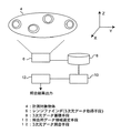
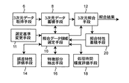
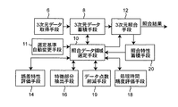
以下の実施の形態では、本件発明に係る3次元物体照合装置を位置姿勢推定に応用する場合を例に説明する。図1は、本発明の実施の形態1に係る3次元物体照合装置の概略を示す模式図である。3次元物体照合装置では、センサ等の3次元データ取得手段6によってある視線方向から見た対象物体4の3次元データを取得し、その計測した3次元データを既知の3次元データ(標準3次元データ)と照合することにより、対象物体4の位置姿勢推定を行う。図示するように、センサ6によって取得した3次元データは、メモリ等の3次元データ蓄積手段8に蓄積され、照合データ領域選定手段10において照合に用いるデータ領域が選定され、3次元データ照合手段12において標準3次元データとの照合が行われた後、照合結果が出力される。計測した3次元データを表すセンサ座標は任意であるが、例えば、センサ6の視線方向をz軸とし、それに直交する平面内にx軸とy軸を取る直交座標をセンサ座標として用いることができる。位置姿勢の推定精度を高めるために複数の方向から物体4の計測を行うこともあるが、その場合には統一したセンサ座標系に変換して標準3次元データとの照合が行われる。
Embodiment 1
In the following embodiments, a case where the three-dimensional object matching device according to the present invention is applied to position and orientation estimation will be described as an example. FIG. 1 is a schematic diagram showing an outline of a three-dimensional object matching apparatus according to Embodiment 1 of the present invention. In the three-dimensional object matching device, three-dimensional data of the target object 4 viewed from a certain line of sight is acquired by a three-dimensional
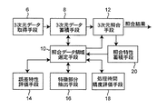
図2は、図1に示す3次元物体照合装置のより詳細な処理構成を示すブロック図である。図2に示すように、照合データ領域選定手段10は、下位モジュールとして誤差特性評価手段14と、特徴部分抽出手段16と、処理時間・精度評価手段18を有する。誤差特性評価手段14では、センサ6と計測点の空間上の位置関係や対象物体4の表面特性(材質、形状)に基づいて各計測点における誤差の推定標準偏差の空間分布(=誤差特性)を算出する。特徴部分抽出手段16では、計測データ中の距離変化の大きな点や曲率の大きな点を選定し、照合処理の際に用いるべきデータ領域の初期候補の抽出処理を行う。処理時間・精度評価手段18では、先に選定されている初期候補のデータ領域の組合せにより達成される処理時間を推定すると共に、そのデータ領域を用いた際の推定精度を先に算出しておいた誤差特性に基づいて評価する。照合データ領域選定手段10は、これらの下位モジュールの動作を制御して必要な情報を得ることにより、各方向別の目標照合精度や目標の処理時間を実現するのに必要なデータ領域が決定される。ここで選定されたデータ領域を用いて3次元照合を行うことにより、高速かつ高精度の照合が可能となる。また、過去に選定したデータ領域とその照合結果は照合特性蓄積手段20に蓄積され、照合データ領域選定手段10における以降の選定処理に活用される。
FIG. 2 is a block diagram showing a more detailed processing configuration of the three-dimensional object matching apparatus shown in FIG. As shown in FIG. 2, the collation data
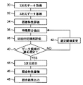
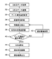
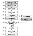
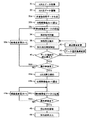
図3は照合の処理フローを示すフロー図である。以下、このフロー図に従って各構成における処理の詳細について説明する。
(3次元データ取得)
まず、3次元データ取得手段6によって対象物体4の3次元立体形状を表す3次元データが取得される(ステップ30)。この3次元データ取得手段6としては、各種の3次元距離測定手段を用いることができ、例えば、2つ以上のカメラを用いて三角測量原理により距離分布計測を行うステレオ方式、パターン投光を行い1つ以上のカメラで観測して三角測量原理に基づいて計測を行う構造化光方式、レーダー光の出射から反射光の受光までの時間を計測する飛行時間法などの各種レンジファインダを用いることができる。3次元データ取得手段6によって得られるデータは、一般にある視点方向から物体4を見たときの距離画像であり、部分的な3次元データである。3次元データは、センサ6を動かしながら複数の視点から計測したデータを複合したものであっても良い。
FIG. 3 is a flowchart showing a verification processing flow. The details of the processing in each configuration will be described below according to this flowchart.
(3D data acquisition)
First, the three-dimensional data representing the three-dimensional shape of the target object 4 is acquired by the three-dimensional data acquisition means 6 (step 30). As the three-dimensional data acquisition means 6, various three-dimensional distance measurement means can be used. For example, a stereo system that performs distance distribution measurement by the triangulation principle using two or more cameras, pattern projection is performed. Use of various rangefinders such as a structured light method that observes with one or more cameras and performs measurements based on the triangulation principle, and a time-of-flight method that measures the time from emission of radar light to reception of reflected light it can. Data obtained by the three-dimensional
(3次元データ蓄積)
次に、3次元データ取得手段6によって取得した3次元データを3次元データ蓄積手段8に蓄積する(ステップ32)。3次元データ蓄積手段8は、計測した3次元データを記憶可能なメモリであれば良く、特に種類は問わない。また、3次元データ蓄積手段8には、計測した3次元データの他に、照合すべき対象物体4の標準3次元データも蓄積されている。標準3次元データは、既知の姿勢の物体4を計測することによって得た3次元データでも良いし、CAD設計情報などから生成された3次元データであっても良い。
(3D data storage)
Next, the three-dimensional data acquired by the three-dimensional
(照合データ領域選定)
次に、照合データ領域選定手段10が、下位動作モジュールである誤差特性評価手段14、特徴部分抽出手段16、処理時間・精度評価手段18の動作制御を行って総合的な評価を行った上でデータ領域選定を行う(ステップ34〜42)。これにより座標の各方向別の目標照合精度や目標の処理時間を実現するのに必要なデータ領域が選定される。以下、3つの下位動作モジュールについて、その動作をフロー順に説明していき、次いでこれらを総合的に評価すると共に動作制御を行う照合データ領域選定手段の動作について述べる。なお、3つの下位動作モジュールは基本的には図3に示すようにシーケンシャルに処理されるが、照合データ領域選定手段10で適切なデータ領域の選定ができなかった場合には、特徴部分抽出手段16での閾値パラメータを変更するなどして、目標の位置姿勢推定精度や処理時間を達成するように1回以上動作する構成となっている。
(Verification data area selection)
Next, after the collation data region selection means 10 performs operation control of the error characteristic evaluation means 14, the feature portion extraction means 16, and the processing time / accuracy evaluation means 18 that are lower-order operation modules, comprehensive evaluation is performed. Data area selection is performed (
−誤差特性評価
まず、誤差特性評価手段14では、3次元データ蓄積手段8に蓄積された3次元データの各計測点について誤差特性の評価を行う(ステップ34)。ここで評価する誤差特性は、各計測点が持つ計測誤差の空間的な分布を評価したものであり、例えばセンサ座標の各座標軸方向における計測誤差の推定標準偏差として表される。ここで評価する誤差特性の種類は特に限定されないが、例えば、センサ6の構造によって決まる誤差特性や、対象物体4の表面反射特性(材質、形状)によって決まる誤差特性などが挙げられる。
-Error Characteristic Evaluation First, the error
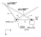
センサ6の構造によって決まる誤差特性について図4を参照しながら説明する。図4に示すように、センサ(=3次元データ取得手段)6として構造化光方式のものを用いた場合、センサ6は主としてパターン投光器22と受光カメラ部24から構成され、両者はベースラインと呼ばれる一定距離L0だけ離して配置される。ここでは図面正面から見て左側にパターン投光部22が配置され、右側に受光カメラ部24が配置された場合を考える。センサ6の構造に由来する計測誤差の大きさは、対象物体4の計測点とセンサ6との空間的な位置関係に依存して変化する。即ち、このセンサ6では、受光カメラ24のカメラ中心24aから計測点に向かって延びる線分をL1とし、パターン投光器22の投光器中心22aから計測点に向かって照射方向に延びる線分をL2とすると、計測点は線分L1と線分L2の交差点26又は26’となり、ベースラインL0と線分L1と線分L2から構成される三角形から三角測量の原理に基づいて計測点までの距離が算出される。通常、線分L1及びL2は空間的な幅を持った線分であるため、その交差点26又は26’はある面積をもったひし形領域となり、この領域の広がり分だけ距離の計測誤差が生じることになる。この交差領域の広がりは計測点とセンサ6の空間的な位置関係によって変化する。
The error characteristics determined by the structure of the
例えば、カメラ中心24a及びパターン投光器中心22aのいずれに対しても右側または左側に計測点がある場合、図4左側に示すようにL1及びL2の交差角度が鋭角となり、線分L1と線分L2の交差領域26は縦長のひし形となる。この計測誤差の誤差ベクトルは、例えば、ひし形の2本の対角線ベクトルによって近似することができるため、特定の方向(この場合は線分L1方向)への誤差ベクトルが特に大きくなる。一方、計測点がカメラ中心24aと投光器中心22aの中間に位置する場合には、線分L1と線分L2は前述の場合よりも鈍い角度で交わるため、長方形に近いひし形領域26’となるか、少なくとも前述の場合よりも緩い角度のひし形領域26’となる。また、ひし形領域26’は前述の場合のひし形領域26よりも小さくなる。このためひし形領域26’の2つの対角線ベクトルによって近似した誤差ベクトルは、前述の場合の誤差ベクトルよりも小さく、また2つの誤差ベクトルの大きさがほぼ等しくなるため特定の方向への依存性も少なくなる。評価した各計測点における誤差ベクトルを、所定の座標系の各座標軸に射影することによって、センサ6の構造の由来する計測誤差の大きさを各座標軸方向ごとに評価することができる。具体的には、2本の対角線ベクトルの座標軸への射影成分を座標軸ごとに足し合わせれば、各方向における計測誤差の大きさを評価することができる。
For example, if for any
このセンサ構造に由来する計測誤差は、センサ6の構造に関する情報(上記例では線分L1とL2の幅)とセンサ6に対する空間上の位置(センサ空間での座標)から計算することができる。センサ構造に由来する計測誤差をセンサ空間での各座標軸について予め計算しておき、センサによって計測した各計測点の座標に対応付ければ、センサ構造に由来する誤差特性の評価を高速に行うことができる。
Measurement error derived from this sensor structure, be calculated from information about the structure of the
次に、対象物体4の表面反射特性(材質、形状)によって決まる誤差特性の評価について説明する。対象物体4の材質や形状は様々であり、それに応じてパターン投光器22から対象物体4に照射された光が受光カメラ24方向に反射する反射割合が変化する。この反射割合が小さいほど、受光カメラ24で感知する計測信号のS/N比が低下するため計測誤差が大きくなる。例えば、対象物体4の計測点が反射率の低い素材である場合には、受光カメラ24側への帰還光成分が少なくなり、計測信号のS/N比が低下することで計測誤差が大きくなる。また、対象物体4の計測点における面方位が投光器22に正対するような配置となる場合も、受光カメラ24側への帰還光成分が少なくなり、S/N比が低下することで計測誤差が大きくなる。対象物体4の面方位の影響は、対象物体の表面が鏡面反射性である場合に特に大きい。逆に、対象物体の表面が完全拡散面である場合には対象物体4の面方位の影響は小さくなる。 Next, evaluation of error characteristics determined by the surface reflection characteristics (material, shape) of the target object 4 will be described. The material and shape of the target object 4 are various, and the reflection ratio at which the light irradiated to the target object 4 from the pattern projector 22 reflects in the direction of the light receiving camera 24 changes accordingly. The smaller the reflection ratio, the larger the measurement error because the S / N ratio of the measurement signal sensed by the light receiving camera 24 is lowered. For example, when the measurement point of the target object 4 is a material having a low reflectance, the feedback light component to the light receiving camera 24 side is reduced, and the S / N ratio of the measurement signal is reduced to increase the measurement error. . Further, when the plane orientation at the measurement point of the target object 4 is directly opposite to the projector 22, the component of feedback light to the light receiving camera 24 side is reduced, and the S / N ratio is reduced, resulting in a measurement error. growing. The influence of the surface orientation of the target object 4 is particularly great when the surface of the target object is specular. On the contrary, when the surface of the target object is a complete diffusion surface, the influence of the plane orientation of the target object 4 becomes small.
この対象物体4の表面反射特性(材質、形状)によって決まる計測誤差は、例えば、対象物体4を置いたときに受光カメラ24で受光した輝度信号から対象物体4を置かないときに受光カメラ24で受光した輝度信号を減算することによって簡単に評価することができる。即ち、対象物体4を置いたときと置かないときの輝度信号の差は、対象物体4から受光カメラ24に向かって反射した光の割合に相当するため、これが大きいほど計測信号のS/N比が大きくなり、計測誤差が小さくなる。このようにして評価した計測誤差は、簡易的には等方的に発生すると近似できる。従って、前述のセンサ構造由来の誤差特性に加えて対象物体4の表面反射特性によって決まる誤差特性を考慮する場合、センサ構造に基づく計測誤差のx、y、z各成分に対して、表面反射特性から導いた計測誤差に相当する係数を乗算することにより表面反射特性よる計測誤差の影響を加味することができる。 The measurement error determined by the surface reflection characteristics (material, shape) of the target object 4 is, for example, that the light receiving camera 24 does not place the target object 4 from the luminance signal received by the light receiving camera 24 when the target object 4 is placed. This can be easily evaluated by subtracting the received luminance signal. That is, the difference in luminance signal between when the target object 4 is placed and when it is not placed corresponds to the ratio of the light reflected from the target object 4 toward the light receiving camera 24. Therefore, the larger this is, the S / N ratio of the measurement signal. Increases and the measurement error decreases. The measurement error evaluated in this way can be approximated to be generated isotropically simply. Therefore, in consideration of the error characteristic determined by the surface reflection characteristic of the target object 4 in addition to the error characteristic derived from the sensor structure, the surface reflection characteristic for each of the x, y, and z components of the measurement error based on the sensor structure. By multiplying the coefficient corresponding to the measurement error derived from the above, the influence of the measurement error due to the surface reflection characteristics can be taken into account.
−特徴部分抽出
次に特徴部分抽出手段16では、計測した3次元データの中から照合に適したデータ領域を抽出する(ステップ36)。例えば、3次元データから予め決められた標準的なサイズのデータ領域を切り出し、各データ領域について所定の形状特徴値を算出した上で、形状特徴値が閾値を超えるデータ領域を初期候補として選択する。ここで形状特徴値は、照合に適したデータ領域を判断できる指標となるものであれば良い。例えば、あるデータ領域が形状的にユニークであったり、そのデータ領域の濃淡テクスチャがユニークであれば照合に適していると言える。従って、形状特徴値の具体例としては、そのデータ領域における距離データの分散、曲率の分散、曲率(それ自体)、ヒストグラム分布、ヒストグラムの平均や標準偏差、空間周波数(フーリエ変換の係数等)等が挙げられる。
-Feature part extraction Next, the feature part extraction means 16 extracts a data area suitable for collation from the measured three-dimensional data (step 36). For example, a data area of a predetermined standard size is cut out from three-dimensional data, a predetermined shape feature value is calculated for each data area, and a data area whose shape feature value exceeds a threshold is selected as an initial candidate. . Here, the shape feature value may be an index that can determine a data area suitable for collation. For example, it can be said that a certain data area is suitable for collation if the shape is unique in shape or the shading texture of the data area is unique. Therefore, specific examples of the shape feature value include distance data variance, curvature variance, curvature (by itself), histogram distribution, histogram average and standard deviation, spatial frequency (Fourier transform coefficient, etc.), etc. Is mentioned.
例えば、距離データの分散を形状特徴値とする場合について説明する。一般に計測した3次元データ(距離データ)中で距離変化の大きな領域は、空間的ユニーク性が高いため、位置姿勢推定や物体識別に有効な部分となることが知られている。距離の変化が大きなデータ領域を選定するには、例えば、以下の選定アルゴリズム1ような処理を行えば良い。即ち、Step1では、センサの受光カメラ24からの視線方向に垂直な面内で等間隔に区切った8方向(22.5度間隔)を設定し、各方向について距離データの分散値を算出する。そして、Step2において、各方向のデータ分散のうち最小のものが閾値を越えていれば初期候補として選定する。
<選定アルゴリズム1>
Step1 3次元計測データ中、等間隔に区切った8方向について各方向別の距離データ分散値算出
Step2 if(8方向中最も小さな分散値>閾値) then 選択
For example, the case where the variance of distance data is used as the shape feature value will be described. In general, a region having a large distance change in three-dimensional data (distance data) measured is known to be an effective portion for position and orientation estimation and object identification because of its high spatial uniqueness. In order to select a data region having a large change in distance, for example, processing such as the following selection algorithm 1 may be performed. That is, in Step 1, eight directions (22.5 degree intervals) divided at equal intervals in a plane perpendicular to the line-of-sight direction from the light receiving camera 24 of the sensor are set, and the dispersion value of the distance data is calculated for each direction. In Step 2, if the minimum data distribution in each direction exceeds the threshold, it is selected as an initial candidate.
<Selection algorithm 1>
Step1 Calculate the distance data variance value for each direction in 8 directions divided at regular intervals in 3D measurement data
Step2 if (smallest variance in 8 directions> threshold) then select
次に、曲率の分散を形状特徴値とする場合について説明する。曲率の変化が大きなデータ領域を選定するには、例えば、以下の選定アルゴリズム2のような処理を行えば良い、即ち、Step1では、選定アルゴリズム1と同様に等間隔に区切った8方向について各方向における法線単位ベクトルの分散値を算出する。次に、Step2において、各方向のデータ分散のうち最小のものが閾値を越えていれば初期候補として選定する。
<選定アルゴリズム2>
Step1 3次元計測データ中、等間隔に区切った8方向について、各方向の法線成分の分散値算出
Step2 if (8方向中最も小さな変化値の分散値>閾値) then 選択
Next, a case where the dispersion of curvature is a shape feature value will be described. In order to select a data area with a large change in curvature, for example, processing like the following selection algorithm 2 may be performed, that is, in Step 1, each direction is divided into eight directions divided at equal intervals as in the selection algorithm 1. The variance value of the normal unit vector at is calculated. Next, in Step 2, if the smallest data distribution in each direction exceeds the threshold, it is selected as an initial candidate.
<Selection algorithm 2>
Step1 Calculate the variance of normal component in each direction for 8 directions divided at regular intervals in 3D measurement data
Step2 if (dispersion value of smallest change value in 8 directions> threshold) then select
ここでデータ分散の最小値を代表値として閾値と比較しているが、データ分散の代表値の取り方は任意であり、例えばデータ分散の平均値を閾値と比較しても良い。但し、データ分散の最小値を代表値とすれば、照合に不適切な領域の誤選定を防止するのに有効である。例えば、データ分散の最大値を閾値を比較した場合、全体として照合に不適切であるが、ある一方向だけが偶然にデータ分散が大きな領域が誤って選定される場合がある。尚、データ分散を評価する方向は8方向には限定されず、対象物体の形状に合わせて適宜選択すれば良い。評価方向を設定する面も、視線方向に垂直な面には限定されず、例えば対象物体のデータ領域の平均的な法線に垂直な面であっても良い。 Here, the minimum value of data distribution is compared with the threshold value as a representative value, but the method of taking the representative value of data distribution is arbitrary, and for example, the average value of data distribution may be compared with the threshold value. However, if the minimum value of data distribution is used as a representative value, it is effective to prevent erroneous selection of areas inappropriate for collation. For example, when a threshold value is compared with the maximum value of data distribution, it is unsuitable for collation as a whole, but an area where the data distribution is large accidentally in only one direction may be selected by mistake. Note that the direction in which the data distribution is evaluated is not limited to eight directions, and may be appropriately selected according to the shape of the target object. The plane for setting the evaluation direction is not limited to a plane perpendicular to the line-of-sight direction, and may be, for example, a plane perpendicular to the average normal line of the data area of the target object.
−処理時間・精度評価
次に、処理時間・精度評価手段18において、特徴部分抽出手段16で選定されたデータ領域の初期候補から各種組合せに対する推定照合精度と推定処理時間算出を行う(ステップ38)。まず、推定照合精度は、先の誤差特性評価手段14で評価した誤差特性に基づいて算出できる。例えば、誤差特性評価手段14によって各計測点における誤差ベクトル、即ち、x、y、z方向の計測誤差の推定標準偏差を見積もっているため、データ領域内の全ての誤差ベクトルを合成すれば、データ領域全体が示す計測誤差をx、y、z方向について知ることができる。ここでデータ領域の大きさがそれぞれ異なる場合には、合成した誤差ベクトルをデータ領域内の計測点数で割って平均誤差ベクトルを求めても良い。また、データ領域内の各計測点が持つ誤差ベクトルの分散が、小さいほうが照合精度が良好となる傾向にある。そこで誤差ベクトルの分散を計算して照合精度の指標としても良い。この分散は、誤差ベクトルのx、y、z成分の各々について計算しても良い。また、誤差ベクトルの合成と誤差ベクトルの分散の両方を組合せて照合精度の指標を得ても良い。
-Processing time / accuracy evaluation Next, the processing time /
次に、推定処理時間は、データ領域面積の2乗に比例するので、あらかじめ蓄積しておいた単位点数あたりの照合時間との比例計算により計算できる。なお、処理時間・精度評価手段では、所定のデータ領域の組合せについて評価を行っても良いし、データ領域ごとに評価を行っても良い。 Next, since the estimated processing time is proportional to the square of the data area, it can be calculated by proportional calculation with the collation time per unit point accumulated in advance. The processing time / accuracy evaluation means may evaluate a predetermined combination of data areas, or may evaluate each data area.
−照合データ領域選定
次に、照合データ領域選定手段10において、上記に述べた3つの下位動作モジュールである誤差特性評価手段14、特徴部分抽出手段16、処理時間・精度評価手段の出力から得られる評価値を基にデータ領域の選定を行い、データ領域の選定が適切にできなかった場合は選定の閾値を変えるなどして特徴部分の抽出からやり直す(ステップ40、42)。具体的には、照合データ領域選定手段10において、特徴部分抽出手段16で選定されたM個の初期候補データ領域から目標の照合精度と処理時間を達成できるデータ領域の組合せを探索する。
-Collation data area selection Next, the collation data area selection means 10 obtains from the outputs of the error characteristic evaluation means 14, the characteristic part extraction means 16 and the processing time / accuracy evaluation means, which are the three subordinate operation modules described above. A data area is selected based on the evaluation value, and if the data area cannot be selected properly, the characteristic portion is extracted again by changing the selection threshold (
例えば、最初に処理時間・精度評価手段18で得た推定処理時間に基づいて、処理時間を目標時間内に収めるために用いるべきデータ領域数N(M≧N)が決定される。組合せに用いるデータ領域数Nが決定されると、処理時間・精度評価手段18において推定照合精度を得ることができるので、目標照合精度を達成できるかどうかを判断する。x、y、z方向別に目標となる照合精度(位置姿勢推定の許容誤差等)が異なる場合には、各方向ごとに推定照合精度を目標精度と比較することにより、適切なデータ領域の組合せが選定できる。尚、この組合わせを選定する際、組合わせ数が多くなると、検証に時間がかかるため、遺伝アルゴリズムなどの準最適化手法を用いても良い。尚、目標処理時間を達成するデータ領域数Nが初期候補数Mとほぼ等しい場合(M≒N)や、目標とする方向別の精度を達成するために異なる法線方向成分を持つ候補領域を組合せる必要がある場合には、組合せ数が数百個程度に抑えられるのであれば総当り的に組合せを検証しても良い。また、後述する照合特性蓄積手段20に蓄積されている過去の組合せ例や、あらかじめ与えられている標準的な組合せ例などに応じて、組合せを優先、限定するなどして評価を行うことも可能である。
For example, the number N of data areas (M ≧ N) to be used for keeping the processing time within the target time is determined based on the estimated processing time first obtained by the processing time / accuracy evaluation means 18. When the number N of data areas used for the combination is determined, the processing time /
こうして、目標とする照合精度と処理時間を満たす組合せを見つけることができる。複数の組合せ候補が存在する場合には、そのうち最も照合精度のよいものを選ぶなどして候補を絞り込む。なお、目的の照合精度及び処理時間を満たす組合せが存在しない場合は、処理時間の増加を許容して解を見つけるために照合データ領域選定手段10における目標処理時間を増加するか、又は、初期候補を増やすために特徴部分抽出手段16における閾値を変更する等して、再度選定処理を実行する(ステップ42)。なお、無限ループに陥らないようにするため、一定回数以上の処理が繰り返された場合には、処理を打ち切り、それまでに得られた結果のうち、最適な結果を出力するとともに注意メッセージを出力する。尚、ここでは選択するデータ領域が、複数のデータ領域の組合せである場合を中心に説明したが、十分な照合精度が得られる場合には単一のデータ領域を選定しても良い。 In this way, a combination that satisfies the target collation accuracy and processing time can be found. If there are a plurality of combination candidates, the candidates are narrowed down by selecting the one with the highest matching accuracy among them. If there is no combination that satisfies the target collation accuracy and processing time, the target processing time in the collation data region selection means 10 is increased to allow the increase in processing time and find a solution, or the initial candidate In order to increase the selection portion, the selection process is executed again by changing the threshold value in the feature portion extraction means 16 (step 42). In order not to fall into an infinite loop, if the process is repeated more than a certain number of times, the process will be aborted, and the optimum result will be output and a caution message will be output. To do. Here, the case where the data area to be selected is a combination of a plurality of data areas has been mainly described, but a single data area may be selected when sufficient matching accuracy is obtained.
以上の評価結果を用いることで、推定精度及び処理時間見込みを最もよく満たすものを選ぶこともできるし、複数の組合せ候補をリストアップしておき、さらに別の基準と組合せて選定することも可能である。ここで、別の選定基準としては2次元画像処理と組合せて表面のテクスチャ情報も利用して選定を行うことなどが考えられる。例えば、ステップ36から38と平行して3次元データの輝度値に対してSUSANオペレータ等の表面テクスチャに基づく特徴選定オペレータを実行し、その結果得られた特徴部分が含まれるようにデータ領域の組合せを選定しても良い。尚、この場合は距離データと輝度データの両方を用いて照合を行う。
By using the above evaluation results, it is possible to select the one that best satisfies the estimation accuracy and the processing time estimate, or list a plurality of combination candidates and select them in combination with other criteria. It is. Here, as another selection criterion, it is conceivable to perform selection using surface texture information in combination with two-dimensional image processing. For example, in parallel with
(3次元データ照合)
次に、3次元データ照合手段12において、照合データ領域選定手段10によって選定されたデータ領域又はデータ領域同士の組合せを3次元データ蓄積手段8に蓄積された標準3次元データと照合する。ここで照合には、3次元データ同士の照合が可能な種々の照合手法を用いることができる。例えば、非特許文献1に記載されたICPアルゴリズム法、非特許文献2に記載された計測誤差を考慮した照合法、池内克史による「物体認識と認識プログラムの自動生成」(人工知能学会誌、vol.4、No.1、pp.30-42、1989)に紹介された種種の幾何推論システム、特開平6−109451号に記載されたようなアスペクト姿勢への射影による予め登録した代表姿勢と照合する方法、等を用いることができる。中でもICPアルゴリズムを用いれば、任意の形状を扱うことができ、しかも高精度の照合が可能となる点で有利である。
(3D data verification)
Next, the three-dimensional
ICPアルゴリズムでは、ともに点群として表現された2つの3次元データ、即ち計測された3次元データと標準3次元データの間で、一方の3次元データのそれぞれの点から他方の3次元データの中で最も近い点までの距離の2乗和を最小化することにより2つの3次元データが最も良く重なるような座標変換を得る。ここで本件発明では、計測された3次元データの全体について照合を行うのではなく、選定されたデータ領域についてのみ照合を行う。このとき照合対象となる標準3次元データからも対応するデータ領域を切り出す必要があるが、対象物体4の微小な移動が予想される場合には、標準3次元データにおいて過去の照合で一致した部分から予想される移動分だけ広げた範囲から複数のデータ領域を切り出し、順次照合すれば良い。対象物体4が完全自由回転をしている等、移動量や方向の予測が困難であるときには、標準3次元データの全体から一致するデータ領域を探索する必要があるため、後述する多重解像度化データを用いて照合することが有効である。 In the ICP algorithm, between two pieces of three-dimensional data that are both represented as a point cloud, that is, between measured three-dimensional data and standard three-dimensional data, each point in one of the three-dimensional data is transferred to the other three-dimensional data. By minimizing the sum of the squares of the distances to the nearest point, coordinate transformation that best overlaps the two three-dimensional data is obtained. Here, in the present invention, verification is not performed for the entire measured three-dimensional data, but only for the selected data region. At this time, it is necessary to cut out a corresponding data area from the standard three-dimensional data to be collated. However, if a minute movement of the target object 4 is expected, a portion matched in the past collation in the standard three-dimensional data. A plurality of data areas may be cut out from a range expanded by the amount of movement expected from, and sequentially verified. When it is difficult to predict the amount of movement or the direction, for example, when the target object 4 is completely free rotating, it is necessary to search for a matching data area from the entire standard three-dimensional data. It is effective to collate using.
(照合特性蓄積、照合結果出力)
こうして最終的な位置姿勢推定結果が得られると、照合に用いたデータ領域や照合結果等の情報が照合特性蓄積手段20に蓄積された後、照合結果が出力される(ステップ46、48)。尚、照合特性蓄積手段20には、過去の照合結果の他に、照合データ領域選定手段10が3つの下位動作モジュールを動作制御する際や、各モジュールが評価を行うための各種照合特性を保持する。例えば、評価を行う際の標準領域サイズや標準的な組合せ例に関する情報などが過去の照合結果などから蓄積されており、これを照合データ領域選定手段において優先的な組合せとして利用する。
(Verification characteristics accumulation, verification result output)
When the final position / orientation estimation result is obtained in this manner, information such as the data area used for the collation and the collation result is accumulated in the collation
尚、本実施の形態では、位置姿勢推定の対象となる物体について計測した3次元データから特徴部分であるデータ領域を選定し、既知の標準3次元データと照合する場合について説明したが、3次元照合には基本的に双方向性があるため、この逆の処理を行っても良い。即ち、既知の3次元データから特徴部分であるデータ領域を選定しておき、位置姿勢推定の対象となる物体について計測した3次元データと照合しても良い。この場合は、既知の3次元データが本件発明における「3次元データ」となり、位置姿勢推定の対象となる物体について計測した3次元データが「標準3次元データ」となる。尚、既知の3次元データを計測によって得る場合、構成や処理フローは図2及び図3と同様となる。 In the present embodiment, a case has been described in which a data region that is a characteristic portion is selected from three-dimensional data measured for an object that is a target of position and orientation estimation and collated with known standard three-dimensional data. Since the collation is basically bidirectional, the reverse process may be performed. In other words, a data area that is a characteristic part is selected from known three-dimensional data, and may be collated with three-dimensional data measured for an object that is a target of position and orientation estimation. In this case, the known three-dimensional data becomes “three-dimensional data” in the present invention, and the three-dimensional data measured for the object to be subjected to position / orientation estimation becomes “standard three-dimensional data”. In the case where known three-dimensional data is obtained by measurement, the configuration and processing flow are the same as those shown in FIGS.
実施の形態2
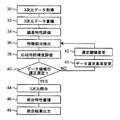
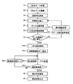
図5は、本発明の実際の形態2に係る3次元物体照合装置を示すブロック図であり、図6は、その処理を示すフロー図である。実施の形態2では、特徴部分抽出手段14における選定基準及び/又は照合データ領域選定手段10で用いる選定基準を変更指示するための選定基準変更手段11を備えており、3次元データを取得、蓄積した後に対象物体4に合わせて選定基準を適宜変更する(ステップ33)。その他の点は、実施の形態1と同様である。ここで、特徴部分抽出手段14の選定基準を変更するとは、データ領域選定の閾値の変更のほか、選定アルゴリズムの変更や、切り出すデータ領域の大きさの変更も含まれる。また、照合データ領域選定手段10で用いる選定基準を変更するとは、目標処理時間や目標照合精度を変えることの他、組合せに用いるデータ領域数の変更、表面テクスチャに基づく選定等の他の選定手法の併用の有無に関する変更なども含まれる。
Embodiment 2
FIG. 5 is a block diagram showing a three-dimensional object matching apparatus according to the actual embodiment 2 of the present invention, and FIG. 6 is a flowchart showing the processing. In the second embodiment, selection
本実施の形態によれば、対象物体の形状によって選定基準を変更することにより、目標精度、目標処理時間を満たす組合せをより適切に選択することが可能となる。例えば、直方体形状の対象物体に対して、計測視野の関係から複数視点からの計測が行われ、かつ、各計測視点における計測データが角を含まない平面部のみであった場合などは、実施の形態1で述べた選定アルゴリズム1,2では、ユニーク性のある部分が存在しないことになる。しかし、平面3面があれば空間的な位置姿勢拘束条件となりうるので、こうした場合には法線方向が直交する平面3面を照合すべきデータ領域として抽出すればよい。選定基準変更手段11では、こうした場合に対応して、オペレータが対象物体に応じて特徴部分抽出手段16における選定閾値(又はアルゴリズム)や照合データ領域選定手段における選定基準を切り替えるように変更指示を与えることができ(ステップ33)、例えば、対象物体の平面部からあらかじめ決めておいた中央領域を選定するように動作させる。また、照合の際には、通常の照合と異なり、平面の法線方向の位置照合結果のみを有効な結果として用いるなどの動作制御が必要となるため、3次元照合手段12での照合動作も変更することが好ましい。本実施の形態のように、選定基準変更手段11を備えたことにより、処理の柔軟性を向上させることができる。
According to the present embodiment, it is possible to more appropriately select a combination that satisfies the target accuracy and the target processing time by changing the selection criterion depending on the shape of the target object. For example, when a rectangular parallelepiped target object is measured from multiple viewpoints due to the measurement field of view, and the measurement data at each measurement viewpoint is only a flat part that does not include a corner, etc. In the selection algorithms 1 and 2 described in the form 1, there is no unique part. However, if there are three planes, it can be a spatial position and orientation constraint condition. In such a case, the three planes having normal directions orthogonal thereto may be extracted as data areas to be collated. In the selection
実施の形態3
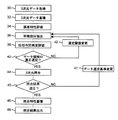
図7は、本発明の実際の形態3に係る3次元物体照合装置の処理を示すフロー図である。実施の形態3では、実施の形態2においてオペレータが変更していた選定基準を、データ領域の選定結果に応じて選定基準変更手段が自動的に変更するようにする(ステップ41)。その他の点は、実施の形態2と同様である。
Embodiment 3
FIG. 7 is a flowchart showing the processing of the three-dimensional object matching device according to the actual embodiment 3 of the present invention. In the third embodiment, the selection criterion changing means automatically changes the selection criterion changed by the operator in the second embodiment in accordance with the data area selection result (step 41). The other points are the same as in the second embodiment.
本実施の形態では、照合データ選定手段10でデータ領域の選定を行った結果、目標精度、目標処理時間を満たす組合せが得られなかった場合に、自動的に特徴部分抽出手段16における選定基準や照合データ領域選定手段における選定基準を切り替える(ステップ41)。この変更にあたっては、特徴部分抽出手段16において、実施の形態1で述べた選定基準1、2では初期候補群が得られない場合に、実施の形態2述べたような平面構成に応じた選定基準に自動的に変更して再度処理を行うように動作が制御する。また、選定基準変更手段11によって、実施の形態1における表面テクスチャに基づく選定の併用の有無を切替えても良い。
In the present embodiment, as a result of selecting the data area by the collation data selection means 10, if the combination satisfying the target accuracy and the target processing time is not obtained, the selection criteria in the feature portion extraction means 16 are automatically The selection criteria in the collation data area selection means are switched (step 41). In this change, when the initial candidate group cannot be obtained by the selection criteria 1 and 2 described in the first embodiment in the feature portion extraction means 16, the selection criteria corresponding to the planar configuration as described in the second embodiment. The operation is controlled so that the process is automatically changed to be performed again. In addition, the selection
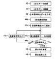
尚、本実施の形態では、照合データ領域選定手段10の選定結果に基づいてデータ選定基準を変更する場合について説明したが、図8に示すように、3次元データ照合手段12により照合した後(ステップ44)、照合結果の適否を判断して(ステップ45)、照合結果がエラー値である等、適切でない場合には選定基準変更手段11によって選定基準を変更しても良い(ステップ41’)。
In the present embodiment, the case where the data selection criterion is changed based on the selection result of the collation data
実施の形態4
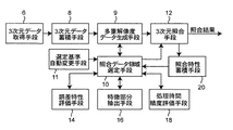
図9は、本発明の実際の形態4に係る3次元物体照合装置を示すブロック図であり、図10は、その処理を示すフロー図である。この実施形態では、図9に示すように、特徴部分抽出手段16で選定したデータ領域に対して、その後の照合処理計算に用いるデータ点数を削減するためのデータ点数削減手段19を備えている。例えば図10に示すように、特徴部分抽出手段によって選定した後(ステップ36)、選定した初期候補に対してデータ点数の削減を行う(ステップ37)。これにより、データ点数をすべて用いた場合には目標とする処理時間を実現できない場合にも、データ点数を減らして処理時間が短縮できるため、目標の処理時間の達成が可能となる。その他の点は、実施の形態3と同様である。
Embodiment 4
FIG. 9 is a block diagram showing a three-dimensional object matching apparatus according to an actual embodiment 4 of the present invention, and FIG. 10 is a flowchart showing the processing. In this embodiment, as shown in FIG. 9, a data point reduction means 19 for reducing the number of data points used for the subsequent collation processing calculation is provided for the data area selected by the feature portion extraction means 16. For example, as shown in FIG. 10, after selection by the feature portion extraction means (step 36), the number of data points is reduced for the selected initial candidate (step 37). As a result, even if the target processing time cannot be realized when all the data points are used, the processing time can be shortened by reducing the number of data points, so that the target processing time can be achieved. The other points are the same as in the third embodiment.
データ点数の削減方法としては、近接する点の平均代表点を用いる方法が一般的である。例えば、3次元データが平面状の各点に対する高さ情報のようなサーフェース形式である場合について説明する。データ点数が2×2の領域について1つの平均代表点を与える処理を行った場合、データ点数は1/4となる。照合対象となるデータ領域内の相互の点を総当りで照合するような手法であれば、この2乗、即ち1/16の計算量で済むため、照合処理を16倍高速化することが可能である。なお、データ削減のための平均化処理は近傍する2点で行なっても良いし、さらに拡大した領域、例えばデータ点数が4×4の領域やそれ以上の領域であっても良い。その他に、対象となる物体4の形状が比較的滑らかな変化を示す場合には、簡易的な間引き処理によってデータ点数を削減することも可能である。例えば、データ点数が2×2の領域や隣接2点のうちから1点を間引き抽出して用いることも可能である。なお、データ点が3次元空間上の格子点に存在するソリッドデータを扱う場合には、2×2×2領域のように3次元方向に隣接するデータに対して同様に処理すればよい。 As a method for reducing the number of data points, a method using an average representative point of adjacent points is generally used. For example, a case will be described in which the three-dimensional data has a surface format such as height information for each planar point. When processing for giving one average representative point is performed for an area having 2 × 2 data points, the data points are ¼. If a technique for collating the points in the data area to be collated with the brute force is used, the calculation amount of this square, that is, 1/16 is sufficient, so the collation process can be accelerated 16 times. It is. It should be noted that the averaging process for data reduction may be performed at two adjacent points, or may be a further enlarged area, for example, an area having 4 × 4 data points or more. In addition, when the shape of the target object 4 shows a relatively smooth change, the number of data points can be reduced by a simple thinning process. For example, it is also possible to use by extracting one point from an area having 2 × 2 data points or two adjacent points. In the case of handling solid data in which data points exist at lattice points in a three-dimensional space, the same processing may be applied to data adjacent in the three-dimensional direction such as a 2 × 2 × 2 region.
ただし、これらの処理では照合点数が減るため、対象物体の形状を表すのに十分なデータ点数が得られない場合には照合精度の低下を生じる可能性がある。そこで、データ削減を行った後(ステップ37)、処理時間・精度評価手段によって予想される照合精度を算出し(ステップ38)、目標の照合精度に対して十分であるかどうかを検証する(ステップ40)。目標の照合精度が得られなかった場合には、選定基準変更手段11において、削減するデータ点数を変更して処理を繰り返す(ステップ40〜42)。これらの処理における照合精度の評価手順は実施の形態1と同様であり、実施の形態1では用いられるデータ点が削減処理される前のものであったのに対し、本実施例では削減処理された後のデータ点である点のみが異なる。本実施の形態によれば、データ点数削減によって高速度処理を実現しつつ、照合精度を維持できるという効果が得られる。
However, since the number of matching points is reduced in these processes, there is a possibility that the matching accuracy is lowered when a sufficient number of data points cannot be obtained to represent the shape of the target object. Therefore, after performing data reduction (step 37), the collation accuracy expected by the processing time / accuracy evaluation means is calculated (step 38), and it is verified whether the target collation accuracy is sufficient (step 38). 40). If the target collation accuracy is not obtained, the selection
実施の形態5
図11は、本発明の実際の形態5に係る3次元物体照合装置の処理を示すフロー図である。本実施の形態では、実施の形態4におけるデータ点数削減処理が多重解像度にわたって実行される場合について、さらに「3次元照合手段」における利用方法も含めて説明する。本実施の形態におけるブロック図は、実施の形態4の図9と同じである。
Embodiment 5
FIG. 11 is a flowchart showing the processing of the three-dimensional object matching device according to the actual embodiment 5 of the present invention. In the present embodiment, the case where the data point reduction process in the fourth embodiment is executed over multiple resolutions will be described, including the usage method in the “three-dimensional matching unit”. The block diagram in the present embodiment is the same as FIG. 9 in the fourth embodiment.
実施の形態4では、データ点数削減手段におけるデータ点数の削減処理を1段階で行う場合について説明したが、本実施の形態ではデータ点数削減を異なるデータ削減率を用いて多段階で行い、多重解像度のデータを得る。例えば、特徴部分抽出手段によってデータ領域の初期候補の選定が終わった後(ステップ36)、初期候補のあるデータ領域に対して、まずデータ点数が2×2の領域で平均代表点を選定し、次に4×4領域で平均代表点選定し、さらに8×8領域で平均代表点を選定すると(ステップ37)、それぞれ1/4、1/16、1/64のデータ点数に削減した3種類のデータが得られたことになる。データ点数の削減率が高いほど低解像度となるため、上記の処理により多重解像度のデータが得られる。データ点数削減を行った後の多重解像度のデータに対して処理時間・精度評価を行い(ステップ38)、データ領域の選定を行う(ステップ40)。 In the fourth embodiment, the case where the data point reduction processing in the data point reduction means is performed in one stage has been described. In the present embodiment, the data point reduction is performed in multiple stages using different data reduction rates, and multiple resolutions are obtained. Get the data. For example, after the selection of the initial candidate for the data area is completed by the feature portion extraction means (step 36), for the data area with the initial candidate, first, an average representative point is selected in the area with 2 × 2 data points, Next, if the average representative point is selected in the 4 × 4 area and then the average representative point is selected in the 8 × 8 area (step 37), three types are reduced to 1/4, 1/16, and 1/64 data points, respectively. This is the result. Since the higher the reduction rate of the number of data points, the lower the resolution, the multi-resolution data can be obtained by the above processing. The processing time and accuracy are evaluated for the multi-resolution data after the data point reduction (step 38), and the data area is selected (step 40).
ここで処理時間・精度の算定とそれらを目標照合精度や目標処理時間と比較する処理は各解像度ごとに行う。多重解像度処理の場合、異なる解像度に対して異なる目標照合精度を用いることが好ましい。即ち、低解像度データでの照合においては、低い位置精度で粗く位置推定できればよく、高解像度に移行するほど高い目標位置精度となり、最終的に所望の目標位置精度で位置・姿勢推定ができればよい。従って、本実施の形態においては、各解像度において目標とする照合精度を個別に指定可能とすることが好ましい。 Here, processing time / accuracy calculation and processing for comparing them with target collation accuracy and target processing time are performed for each resolution. In the case of multi-resolution processing, it is preferable to use different target collation accuracy for different resolutions. That is, in the collation with low resolution data, it is only necessary to roughly estimate the position with low position accuracy, and the higher the resolution, the higher the target position accuracy, and finally the position / posture can be estimated with the desired target position accuracy. Therefore, in the present embodiment, it is preferable that the target collation accuracy can be individually specified for each resolution.
そして3次元照合手段12において、上記処理によって選択されたデータ領域を用いて照合が行われる(ステップ44a〜44e)。この際、まず最も低解像度のデータのみを用いた照合が行われ、順次高解像度のデータを用いた照合処理が行われる。例えば、照合するデータの解像度が低解像度から高解像度までN段階(Nは1から始まる整数)に分かれていたとする。3次元データの照合を開始すると(ステップ44a)、まず初期解像度の段階を最も低いN=1に設定し(ステップ44b)、次に指定された1段階目の解像度データの照合処理を行い(ステップ44c)、次に設定された解像度の段階Nが最終解像度であるかを判断し(ステップ44d)、最終解像度でなければ解像度の段階を1つ増加してステップ44cに戻る一方(ステップ44e)、最終解像度であれば次の照合特性蓄積に進む。
Then, the three-
ここで、低解像度で得られた照合結果を、より高解像度での照合の際に利用する。「照合結果」とは、照合位置だけであっても良く、照合度などの照合位置以外の情報を含んでいても良い。例えば、低解像度での照合によって得た照合位置を、次に行う高解像度での照合の照合初期値として用いることが好ましい。これにより、低解像度段階での少ないデータ点数で開始した照合処理結果を、より詳細なデータを持つ高解像度段階に引き継ぐことができ、処理速度の向上と精度維持を容易に両立させることができる。 Here, the collation result obtained at a low resolution is used for collation at a higher resolution. The “collation result” may be only the collation position or may include information other than the collation position such as the collation degree. For example, it is preferable to use a collation position obtained by collation at a low resolution as a collation initial value for the next collation at a high resolution. As a result, the collation processing result started with a small number of data points at the low resolution stage can be taken over to the high resolution stage having more detailed data, and both improvement in processing speed and maintenance of accuracy can be easily achieved.
尚、低解像度で得られた照合結果を、より高解像度での照合に利用する場合、照合位置に加えて照合度を引き継いでも良い。例えば、低解像度において複数の位置を推定した場合、各々の照合位置と照合度を合わせて高解像度での照合に引継ぎ、高解像度では照合度が高い照合位置から優先的に照合を進めることが考えられる。 In addition, when the collation result obtained with low resolution is used for collation with higher resolution, the collation degree may be taken over in addition to the collation position. For example, when multiple positions are estimated at a low resolution, it is possible to match each matching position with the matching level and take over the matching at a high resolution, and preferentially advance matching from a matching position with a high matching level at the high resolution. It is done.
実施の形態6
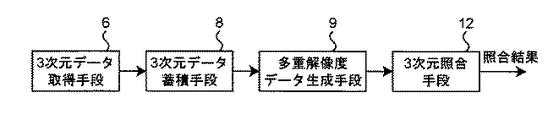
図12は、本発明の実際の形態4に係る3次元物体照合装置を示すブロック図であり、図13は、その処理を示すフロー図である。実施の形態5では、特徴部分抽出手段16で選定されたデータ領域に対してデータ点数を削減する場合について説明したが、本実施の形態では、予め多重解像度化された3次元データに対して、特徴部分抽出手段16でデータ領域の選定を行う場合について説明する。
FIG. 12 is a block diagram showing a three-dimensional object matching apparatus according to an actual embodiment 4 of the present invention, and FIG. 13 is a flowchart showing the processing. In the fifth embodiment, the case where the number of data points is reduced with respect to the data area selected by the feature
照合すべき物体の形状によっては、低解像度において選定すべき特徴部分と高解像度において選定すべき特徴部分が異なる場合がある。特に、高い空間周波数成分の形状を持つ物体については、低解像度のデータではその特徴要素が失われるため、実施の形態5で行ったように高解像度データを基に選定した特徴部分については、低解像度データでは特徴が存在しない部分となっている場合がある。そこで本実施の形態においては、3次元データ蓄積手段8に蓄えられた3次元データから多重解像度データ生成手段9において多重解像度データを生成しておき、特徴部分の選定処理を各解像度データに対して行う。 Depending on the shape of the object to be collated, the feature portion to be selected at the low resolution may be different from the feature portion to be selected at the high resolution. In particular, for an object having a shape of a high spatial frequency component, the characteristic element is lost in the low resolution data. Therefore, the characteristic portion selected based on the high resolution data as in the fifth embodiment is low. The resolution data may be a portion where no feature exists. Therefore, in the present embodiment, multi-resolution data is generated in the multi-resolution data generation means 9 from the three-dimensional data stored in the three-dimensional data storage means 8, and the feature portion selection process is performed for each resolution data. Do.
例えば、図13に示すように、3次元データを蓄積した後(ステップ32)、多重解像度データ生成手段9による処理を開始する(ステップ35a)。生成する多重解像度データの解像度が低解像度から高解像度までN段階(Nは1から始まる整数)に分かれているとする。まず初期解像度の段階を最も低いN=1に設定し(ステップ35b)、次に指定された1段階目の解像度データの生成(データ削減)を行い(ステップ35c)、生成したデータに対して、誤差特性評価(ステップ34)、特徴部分抽出(ステップ36)、処理時間・精度評価(ステップ38)、照合用データ領域の選定(ステップ40)を行った後、設定された解像度の段階Nが最終解像度であるかを判断し(ステップ35d)、最終解像度でなければ解像度の段階を1つ増加してステップ35cに戻る一方(ステップ35
e)、最終解像度であれば次の照合特性蓄積に進む。その後の3次元データ照合手段における照合手順(ステップ44a〜44e)は、実施の形態5と同様に、低解像度データから高解像度データへと順次照合するとともに、低解像度データにおける照合結果を高解像度データにおける照合初期値として利用する。
For example, as shown in FIG. 13, after the three-dimensional data is accumulated (step 32), the processing by the multi-resolution data generation means 9 is started (step 35a). Assume that the resolution of generated multi-resolution data is divided into N stages (N is an integer starting from 1) from low resolution to high resolution. First, the initial resolution stage is set to the lowest N = 1 (
e) If it is the final resolution, the process proceeds to the next collation characteristic accumulation. The subsequent collation procedure (steps 44a to 44e) in the three-dimensional data collation means collates sequentially from the low resolution data to the high resolution data as in the fifth embodiment, and the collation result in the low resolution data is converted into the high resolution data. Used as the initial value for collation.
ここで解像度毎の誤差精度評価、特徴部分抽出、処理時間・精度評価、及び照合用データ領域の選定は、先の実施の形態と同様にして行うことができる。但し、特徴部分抽出のステップ(ステップ36)では、解像度によって切り出すデータ領域の大きさ、選定アルゴリズム、閾値等を変更することが好ましい。例えば、解像度が低い場合には広いデータ領域を切り出し、解像度が上がるにしたがって切り出すデータ領域を狭くしていっても良い。特に、最も解像度が低い場合に切り出すデータ領域の大きさを対象物体の全体としておけば、後のデータ照合において有利である。即ち、3次元データ照合は最も低い解像度のデータから開始するが、照合開始時には物体の位置姿勢が予想できていない場合が多いため、照合に用いる3次元データが部分的なデータ領域であると標準3次元データから対応するデータ領域を切り出すことが難しい。そこで最も低い解像度では物体全体をデータ領域とすることにより、標準3次元データの全体と照合すれば良くなり、照合処理が容易となる。解像度が低い場合には、照合位置精度が低い代わりに単位面積あたりの処理時間が短くなるため、物体全体でデータ照合を行っても目標処理時間の達成が可能である。その後順次高い解像度になるに従って、データ領域を小さくしていけば、短い処理時間で高い照合精度を実現できる。以上の処理により、解像度毎に最適な部分を照合可能となり、多くの対象を簡易な手順で高速かつ高精度に照合可能になる。 Here, error accuracy evaluation for each resolution, feature portion extraction, processing time / accuracy evaluation, and selection of a data area for verification can be performed in the same manner as in the previous embodiment. However, in the feature portion extraction step (step 36), it is preferable to change the size of the data area to be cut out, the selection algorithm, the threshold value, and the like according to the resolution. For example, when the resolution is low, a wide data area may be cut out, and the data area to be cut out may be narrowed as the resolution increases. In particular, if the size of the data area to be cut out when the resolution is the lowest is set as the entire target object, it is advantageous in later data collation. That is, although the three-dimensional data collation starts from the data with the lowest resolution, the position and orientation of the object are often unpredictable at the time of the collation start. It is difficult to cut out the corresponding data area from the three-dimensional data. Therefore, by using the entire object as the data area at the lowest resolution, it is only necessary to collate with the entire standard three-dimensional data, and the collation process becomes easy. When the resolution is low, the processing time per unit area is shortened instead of the low collation position accuracy. Therefore, the target processing time can be achieved even if data collation is performed on the entire object. After that, if the data area is made smaller as the resolution becomes higher, high collation accuracy can be realized in a short processing time. With the above processing, it is possible to collate the optimum part for each resolution, and it is possible to collate many objects with high speed and high accuracy by a simple procedure.
実施の形態7
図14は、本発明の実際の形態7に係る3次元物体照合装置を示すブロック図であり、図15は、その処理を示すフロー図である。本実施の形態では、多重解像度データの生成と照合のみを行い、誤差特性評価や特徴部分抽出は行わない。即ち、3次元データ蓄積手段8に3次元データを蓄積した後(ステップ32)、多重解像度データ生成手段9において3次元データに対してデータ点数削減を異なるデータ削減率を用いて多段階で行い、多重解像度のデータを得る(ステップ35)。多重解像度データを得る手順は、実施の形態5で説明したのと同様である。そして3次元照合手段12において、多重解像度化された3次元データを用いて照合が行われるが(ステップ44a〜44e)、この際、まず低解像度データのみを用いた照合が行われ、順次高解像度データを用いた照合処理が行われる。この際、低解像度で得られた照合結果が、より高解像度での照合の際に利用される。具体的には、低解像度での照合位置や照合度が高解像度での照合初期値として用いられる。これにより、低解像度段階での少ないデータ点数で開始した照合処理結果を、より詳細なデータを持つ高解像度段階に引き継ぐことができ、処理速度の向上と精度維持を容易に両立させることができるという効果がある。
Embodiment 7
FIG. 14 is a block diagram showing a three-dimensional object matching apparatus according to an actual embodiment 7 of the present invention, and FIG. 15 is a flowchart showing the processing. In the present embodiment, only multi-resolution data is generated and collated, and error characteristic evaluation and feature part extraction are not performed. That is, after accumulating 3D data in the 3D data accumulating means 8 (step 32), the multiresolution data generating means 9 performs data point reduction for the 3D data in multiple stages using different data reduction rates, Multi-resolution data is obtained (step 35). The procedure for obtaining multi-resolution data is the same as that described in the fifth embodiment. Then, the three-dimensional collation means 12 performs collation using the multi-resolution three-dimensional data (
4 計測対象物体、 6 3次元データ取得手段、 8 3次元データ蓄積手段、 10 照合データ領域選定手段、 12 3次元データ照合手段、 14 誤差特性評価手段、 16 特徴部分抽出手段、 18 処理時間・精度評価手段。
4 measurement object, 6 3D data acquisition means, 8 3D data storage means, 10 collation data area selection means, 12 3D data collation means, 14 error characteristic evaluation means, 16 feature portion extraction means, 18 processing time / accuracy Evaluation means.
Claims (11)
取得した3次元データを蓄積する3次元データ蓄積手段と、
取得した3次元データと参照すべき標準3次元データとの照合を行う3次元データ照合手段とを備えた3次元物体照合装置であって、
さらに、前記3次元データの各計測点について計測誤差を推定する誤差特性評価手段と、
前記3次元データから1以上のデータ領域を切り出し、所定の形状特徴値が閾値よりも大きなデータ領域を初期候補として選定する特徴部分抽出手段と、
前記データ領域又は前記データ領域同士の組合せについて推定処理時間と推定照合精度を計算する処理時間・精度評価手段と、
前記初期候補から、目標処理時間と目標照合精度を達成するデータ領域又はデータ領域同士の組合せを選定する照合データ領域選定手段とを備え、
前記3次元データ照合手段が、前記照合データ領域選定手段の選定したデータ領域又はデータ領域同士の組合せについて標準3次元データとの照合を行うことを特徴とする3次元物体照合装置。 Three-dimensional data acquisition means for measuring a three-dimensional shape of an object and obtaining three-dimensional data;
3D data storage means for storing the acquired 3D data;
A three-dimensional object collation apparatus comprising a three-dimensional data collation unit that collates acquired three-dimensional data with standard three-dimensional data to be referred to,
And error characteristic evaluation means for estimating a measurement error for each measurement point of the three-dimensional data,
Feature portion extraction means for cutting out one or more data regions from the three-dimensional data and selecting a data region having a predetermined shape feature value larger than a threshold as an initial candidate;
Processing time / accuracy evaluation means for calculating an estimated processing time and an estimated collation accuracy for the data region or a combination of the data regions;
From the initial candidate, comprising a collation data area selection means for selecting a data area or a combination of data areas that achieve the target processing time and target collation accuracy,
3. A three-dimensional object collating apparatus, wherein the three-dimensional data collating unit collates with standard three-dimensional data for a data region selected by the collating data region selecting unit or a combination of data regions.
前記誤差特性評価手段が、前記物体表面で反射して前記受光器に向かう光線の割合に基づいて計測誤差を推定することを特徴とする請求項1又は2に記載の3次元物体照合装置。 The three-dimensional data acquisition means measures a three-dimensional shape by detecting light applied to the object with a light receiver,
3. The three-dimensional object collation apparatus according to claim 1, wherein the error characteristic evaluation unit estimates a measurement error based on a ratio of light rays reflected from the object surface and traveling toward the light receiver.
前記3次元データ照合手段が、前記多重解像度化データを低解像度データから高解像度データへと順次照合するとともに、低解像度データにおける照合結果を高解像度データにおける照合初期値として利用することを特徴とする請求項1乃至7に記載の3次元物体照合装置。 Multi-resolution data generating means for generating multi-resolution data by reducing the number of data points at different reduction rates from the three-dimensional data or data area,
The three-dimensional data collating means sequentially collates the multi-resolution data from low resolution data to high resolution data, and uses a collation result in the low resolution data as a collation initial value in the high resolution data. The three-dimensional object collation apparatus according to claim 1.
前記多重解像度化データ生成手段が、削減率を変更しながら前記3次元データからデータ削減を繰り返すことにより多重解像度化されたデータを生成し、
前記選定基準変更手段が、各解像度のデータについて、前記特徴部分抽出手段で用いる選定基準及び/又は前記照合データ領域選定手段で用いるデータ選定基準を変更しながら選定を繰り返すことを特徴とする請求項8に記載の3次元物体照合装置。 Selection criteria changing means for changing the selection criteria used in the feature portion extraction means and / or the data selection criteria used in the collation data area selection means,
The multi-resolution data generation means generates multi-resolution data by repeating data reduction from the three-dimensional data while changing the reduction rate,
The selection criterion changing means repeats selection for each resolution data while changing the selection criteria used by the feature portion extraction means and / or the data selection criteria used by the collation data area selection means. The three-dimensional object matching device according to 8.
前記特徴部分抽出手段が、前記多重解像度化されたデータの解像度に応じて切り出すデータ領域の大きさを変えるとともに、前記解像度が最小であるときには前記3次元データの略全体からデータ領域を切り出すことを特徴とする請求項8又は9に記載の3次元物体照合装置。 The multi-resolution data generation means generates multi-resolution data by repeating data reduction from the three-dimensional data while changing the reduction rate,
The feature portion extraction means changes the size of the data area to be cut out according to the resolution of the multi-resolution data, and cuts out the data area from substantially the whole of the three-dimensional data when the resolution is minimum. The three-dimensional object collation apparatus according to claim 8 or 9, wherein
取得した3次元データを蓄積する3次元データ蓄積手段と、
取得した3次元データと参照すべき標準3次元データとの照合を行う3次元データ照合手段とを備えた3次元物体照合装置であって、
さらに、前記3次元データ又はデータ領域から異なる削減率でデータ点数を削減することにより多重解像度化されたデータを生成する多重解像度データ生成手段を備え、
前記3次元データ照合手段が、前記多重解像度化データを低解像度データから高解像度データへと順次照合するとともに、低解像度データにおける照合結果を高解像度データにおける照合初期値として利用することを特徴とする3次元物体照合装置。 Three-dimensional data acquisition means for measuring a three-dimensional shape of an object and obtaining three-dimensional data;
3D data storage means for storing the acquired 3D data;
A three-dimensional object collation apparatus comprising a three-dimensional data collation unit that collates acquired three-dimensional data with standard three-dimensional data to be referred to,
Furthermore, it comprises multi-resolution data generation means for generating multi-resolution data by reducing the number of data points at different reduction rates from the three-dimensional data or data area,
The three-dimensional data collating means sequentially collates the multi-resolution data from low resolution data to high resolution data, and uses a collation result in the low resolution data as a collation initial value in the high resolution data. 3D object matching device.
Priority Applications (1)
| Application Number | Priority Date | Filing Date | Title |
|---|---|---|---|
| JP2004108990A JP4383230B2 (en) | 2004-04-01 | 2004-04-01 | 3D object verification device |
Applications Claiming Priority (1)
| Application Number | Priority Date | Filing Date | Title |
|---|---|---|---|
| JP2004108990A JP4383230B2 (en) | 2004-04-01 | 2004-04-01 | 3D object verification device |
Publications (3)
| Publication Number | Publication Date |
|---|---|
| JP2005293350A true JP2005293350A (en) | 2005-10-20 |
| JP2005293350A5 JP2005293350A5 (en) | 2006-12-21 |
| JP4383230B2 JP4383230B2 (en) | 2009-12-16 |
Family
ID=35326197
Family Applications (1)
| Application Number | Title | Priority Date | Filing Date |
|---|---|---|---|
| JP2004108990A Expired - Lifetime JP4383230B2 (en) | 2004-04-01 | 2004-04-01 | 3D object verification device |
Country Status (1)
| Country | Link |
|---|---|
| JP (1) | JP4383230B2 (en) |
Cited By (12)
| Publication number | Priority date | Publication date | Assignee | Title |
|---|---|---|---|---|
| JP2008309603A (en) * | 2007-06-14 | 2008-12-25 | Ihi Corp | Fluorescent flaw detection method and its device |
| JP2011504230A (en) * | 2007-11-15 | 2011-02-03 | シロナ・デンタル・システムズ・ゲゼルシャフト・ミット・ベシュレンクテル・ハフツング | Optical measurement method of objects using trigonometry |
| JP2011179910A (en) * | 2010-02-26 | 2011-09-15 | Canon Inc | Device and method for measuring position and attitude, and program |
| JP2011209116A (en) * | 2010-03-30 | 2011-10-20 | Dainippon Screen Mfg Co Ltd | Three-dimensional position/attitude recognition apparatus and system using the same, method, program |
| JP2015118023A (en) * | 2013-12-19 | 2015-06-25 | 富士通株式会社 | Normal vector extraction apparatus, normal vector extraction method, and normal vector extraction program |
| JP2017068317A (en) * | 2015-09-28 | 2017-04-06 | 富士通株式会社 | Generation method, determination method, program, and information processing apparatus |
| JP2019049533A (en) * | 2017-07-28 | 2019-03-28 | ザ・ボーイング・カンパニーThe Boeing Company | Resolution adaptive mesh for performing 3-D measurement of objects |
| JP2020101437A (en) * | 2018-12-21 | 2020-07-02 | 株式会社日立製作所 | Three-dimensional position/orientation recognition device and method |
| JPWO2021240670A1 (en) * | 2020-05-27 | 2021-12-02 | ||
| JP2022515355A (en) * | 2018-12-10 | 2022-02-18 | 北京図森智途科技有限公司 | Trailer angle measurement method, equipment and vehicle |
| WO2022215248A1 (en) * | 2021-04-09 | 2022-10-13 | 日本電気株式会社 | Person authentication support, person authentication support method, and program |
| US12293668B2 (en) | 2018-12-14 | 2025-05-06 | Beijing Tusen Zhitu Technology Co., Ltd. | Platooning method, apparatus and system of autonomous driving platoon |
-
2004
- 2004-04-01 JP JP2004108990A patent/JP4383230B2/en not_active Expired - Lifetime
Cited By (20)
| Publication number | Priority date | Publication date | Assignee | Title |
|---|---|---|---|---|
| JP2008309603A (en) * | 2007-06-14 | 2008-12-25 | Ihi Corp | Fluorescent flaw detection method and its device |
| JP2011504230A (en) * | 2007-11-15 | 2011-02-03 | シロナ・デンタル・システムズ・ゲゼルシャフト・ミット・ベシュレンクテル・ハフツング | Optical measurement method of objects using trigonometry |
| JP2011179910A (en) * | 2010-02-26 | 2011-09-15 | Canon Inc | Device and method for measuring position and attitude, and program |
| JP2011209116A (en) * | 2010-03-30 | 2011-10-20 | Dainippon Screen Mfg Co Ltd | Three-dimensional position/attitude recognition apparatus and system using the same, method, program |
| JP2015118023A (en) * | 2013-12-19 | 2015-06-25 | 富士通株式会社 | Normal vector extraction apparatus, normal vector extraction method, and normal vector extraction program |
| JP2017068317A (en) * | 2015-09-28 | 2017-04-06 | 富士通株式会社 | Generation method, determination method, program, and information processing apparatus |
| JP2019049533A (en) * | 2017-07-28 | 2019-03-28 | ザ・ボーイング・カンパニーThe Boeing Company | Resolution adaptive mesh for performing 3-D measurement of objects |
| JP7308597B2 (en) | 2017-07-28 | 2023-07-14 | ザ・ボーイング・カンパニー | Resolution-adaptive mesh for performing 3-D measurements of objects |
| JP2022515355A (en) * | 2018-12-10 | 2022-02-18 | 北京図森智途科技有限公司 | Trailer angle measurement method, equipment and vehicle |
| JP7330276B2 (en) | 2018-12-10 | 2023-08-21 | 北京図森智途科技有限公司 | METHOD, DEVICE AND VEHICLE FOR MEASURING TRAILER INCLUSION |
| US12099121B2 (en) | 2018-12-10 | 2024-09-24 | Beijing Tusen Zhitu Technology Co., Ltd. | Trailer angle measurement method and device, and vehicle |
| US12293668B2 (en) | 2018-12-14 | 2025-05-06 | Beijing Tusen Zhitu Technology Co., Ltd. | Platooning method, apparatus and system of autonomous driving platoon |
| JP7159033B2 (en) | 2018-12-21 | 2022-10-24 | 株式会社日立製作所 | 3D position/orientation recognition device and method |
| JP2020101437A (en) * | 2018-12-21 | 2020-07-02 | 株式会社日立製作所 | Three-dimensional position/orientation recognition device and method |
| WO2021240670A1 (en) * | 2020-05-27 | 2021-12-02 | 日本電気株式会社 | Anomaly detection system, anomaly detection device, anomaly detection method, and computer-readable medium |
| JPWO2021240670A1 (en) * | 2020-05-27 | 2021-12-02 | ||
| JP7416233B2 (en) | 2020-05-27 | 2024-01-17 | 日本電気株式会社 | Anomaly detection system, anomaly detection device, anomaly detection method, and program |
| WO2022215248A1 (en) * | 2021-04-09 | 2022-10-13 | 日本電気株式会社 | Person authentication support, person authentication support method, and program |
| JPWO2022215248A1 (en) * | 2021-04-09 | 2022-10-13 | ||
| JP7460016B2 (en) | 2021-04-09 | 2024-04-02 | 日本電気株式会社 | Person authentication support system, person authentication support method and program |
Also Published As
| Publication number | Publication date |
|---|---|
| JP4383230B2 (en) | 2009-12-16 |
Similar Documents
| Publication | Publication Date | Title |
|---|---|---|
| CN109977466B (en) | A three-dimensional scanning viewpoint planning method, device and computer-readable storage medium | |
| KR101003168B1 (en) | Multidimensional Evidence Grid and Its System and Method | |
| US8340400B2 (en) | Systems and methods for extracting planar features, matching the planar features, and estimating motion from the planar features | |
| US11629963B2 (en) | Efficient map matching method for autonomous driving and apparatus thereof | |
| US8325985B2 (en) | Information processing apparatus, information processing method, and computer program | |
| JP4383230B2 (en) | 3D object verification device | |
| JP5759161B2 (en) | Object recognition device, object recognition method, learning device, learning method, program, and information processing system | |
| CN108801268B (en) | Target object positioning method and device and robot | |
| US20120294534A1 (en) | Geometric feature extracting device, geometric feature extracting method, storage medium, three-dimensional measurement apparatus, and object recognition apparatus | |
| US9424649B1 (en) | Moving body position estimation device and moving body position estimation method | |
| Brand et al. | Submap matching for stereo-vision based indoor/outdoor SLAM | |
| JP2014063475A (en) | Information processor, information processing method, and computer program | |
| JP2017151650A (en) | Object state specification method, object state specification apparatus, and conveyance vehicle | |
| US11869146B2 (en) | Three-dimensional model generation method and three-dimensional model generation device | |
| JP2011179910A (en) | Device and method for measuring position and attitude, and program | |
| JP2013178656A (en) | Image processing device, image processing method, and image processing program | |
| CN113111513B (en) | Sensor configuration scheme determining method and device, computer equipment and storage medium | |
| US9816786B2 (en) | Method for automatically generating a three-dimensional reference model as terrain information for an imaging device | |
| Kawashima et al. | Finding the next-best scanner position for as-built modeling of piping systems | |
| KR20220084910A (en) | Method of estimating the location of a moving object using vector map | |
| JP6188345B2 (en) | Information processing apparatus and information processing method | |
| JP5960642B2 (en) | 3D information acquisition method and 3D information acquisition apparatus | |
| KR102547333B1 (en) | Depth Image based Real-time ground detection method | |
| CN119536357A (en) | Docking method of equipment, computer equipment and storage medium | |
| US10914840B2 (en) | Self position estimation apparatus |
Legal Events
| Date | Code | Title | Description |
|---|---|---|---|
| A521 | Request for written amendment filed |
Free format text: JAPANESE INTERMEDIATE CODE: A523 Effective date: 20061102 |
|
| A621 | Written request for application examination |
Free format text: JAPANESE INTERMEDIATE CODE: A621 Effective date: 20061102 |
|
| RD03 | Notification of appointment of power of attorney |
Free format text: JAPANESE INTERMEDIATE CODE: A7423 Effective date: 20061102 |
|
| A131 | Notification of reasons for refusal |
Free format text: JAPANESE INTERMEDIATE CODE: A131 Effective date: 20090707 |
|
| A521 | Request for written amendment filed |
Free format text: JAPANESE INTERMEDIATE CODE: A523 Effective date: 20090813 |
|
| TRDD | Decision of grant or rejection written | ||
| A01 | Written decision to grant a patent or to grant a registration (utility model) |
Free format text: JAPANESE INTERMEDIATE CODE: A01 Effective date: 20090908 |
|
| A01 | Written decision to grant a patent or to grant a registration (utility model) |
Free format text: JAPANESE INTERMEDIATE CODE: A01 |
|
| A61 | First payment of annual fees (during grant procedure) |
Free format text: JAPANESE INTERMEDIATE CODE: A61 Effective date: 20090918 |
|
| FPAY | Renewal fee payment (event date is renewal date of database) |
Free format text: PAYMENT UNTIL: 20121002 Year of fee payment: 3 |
|
| R150 | Certificate of patent or registration of utility model |
Free format text: JAPANESE INTERMEDIATE CODE: R150 |