JP2005292951A - Sensing capsule and sensing system - Google Patents
Sensing capsule and sensing system Download PDFInfo
- Publication number
- JP2005292951A JP2005292951A JP2004103820A JP2004103820A JP2005292951A JP 2005292951 A JP2005292951 A JP 2005292951A JP 2004103820 A JP2004103820 A JP 2004103820A JP 2004103820 A JP2004103820 A JP 2004103820A JP 2005292951 A JP2005292951 A JP 2005292951A
- Authority
- JP
- Japan
- Prior art keywords
- self
- information
- capsule
- sensing
- external
- Prior art date
- Legal status (The legal status is an assumption and is not a legal conclusion. Google has not performed a legal analysis and makes no representation as to the accuracy of the status listed.)
- Pending
Links
Images

Landscapes
- Arrangements For Transmission Of Measured Signals (AREA)
- Fire Alarms (AREA)
- Position Fixing By Use Of Radio Waves (AREA)
- Transceivers (AREA)
Abstract
【課題】 被災状況をリアルタイムに把握できるセンシングカプセルを提供する。
【解決手段】 センシングカプセル2は、外界情報を得るためのセンサ12,14,16,18,19と、自己位置を検出する自己位置検出部30と、外界情報および自己位置情報を送信する無線送受信部42と、センサ、自己位置検出部、および無線送受信部に電力を供給する電源部44と、を多面体状または球状の本体内に収容してなる。かかるセンシングカプセルは、例えば外部から建物内に投げ込まれ、内部の被災状況にかかる情報を外部に送信する。
【選択図】 図3
PROBLEM TO BE SOLVED: To provide a sensing capsule capable of grasping a disaster situation in real time.
A sensing capsule 2 includes sensors 12, 14, 16, 18, and 19 for obtaining external information, a self-position detecting unit 30 that detects self-position, and wireless transmission and reception that transmits external information and self-position information. The unit 42 and the power source unit 44 that supplies power to the sensor, the self-position detecting unit, and the wireless transmission / reception unit are accommodated in a polyhedral or spherical body. Such a sensing capsule is thrown into a building from the outside, for example, and transmits information related to an internal disaster situation to the outside.
[Selection] Figure 3
Description
本発明は、火災などの災害時に建物内に取り残された被災者の救助および救助者の2次災害の防止など災害の規模を最小限に食い止めるために主に利用される、被災状況の把握を行うセンシングカプセルおよびシステムに関する。 The present invention grasps the disaster situation mainly used to stop the scale of disasters such as rescue of victims left in the building at the time of disaster such as fire and prevention of secondary disasters of rescuers. Sensing capsules and systems to perform.
火災や地震が発生した場合、建物内に取り残された人を迅速に救出するともに救助者の安全を確保するために、被災者の位置や通路・部屋の状態(例えば有毒ガスが発生していないか)など被災状況をリアルタイムに把握する必要がある。 In the event of a fire or earthquake, the location of the victim, passage, or room (for example, no toxic gas is generated) to quickly rescue those left behind in the building and ensure the safety of the rescuer It is necessary to grasp the disaster situation in real time.
なお、特許文献1には、自己位置を特定するためのGPS受信機と、観測用センサと、自己位置および観測データを送信する無線送受信機とを内蔵した観測用ブイが開示されている。
現在、建物の外部から内部の被災状況を把握する技術は確立されていない。本発明者は、鋭意研究の結果、被災状況をリアルタイムに把握することのできる発明を完成するに到った。 Currently, no technology has been established to understand the situation of internal damage from outside the building. As a result of earnest research, the present inventor has completed an invention capable of grasping the disaster situation in real time.
本発明に係るセンシングカプセルは、
外界情報を得るための少なくとも一つの外界情報検出手段と、自己位置を検出する自己位置検出手段と、外界情報および自己位置情報を送信する無線送受信手段と、外界情報検出手段、自己位置検出手段、および無線送受信手段に電力を供給する電源部と、を多面体状または球状の本体内に収容することを特徴とする。
The sensing capsule according to the present invention is:
At least one external information detecting means for obtaining external information, self-position detecting means for detecting self-position, wireless transmission / reception means for transmitting external information and self-position information, external information detecting means, self-position detecting means, And a power supply unit for supplying power to the wireless transmission / reception means is housed in a polyhedral or spherical body.
本発明に係るセンシングシステムの一態様は、
外界情報を得るための少なくとも一つの外界情報検出手段と、自己位置を検出する自己位置検出手段と、外界情報および自己位置情報を送信する無線送受信手段と、外界情報検出手段、自己位置検出手段、および無線送受信手段に電力を供給する電源部と、を多面体状または球状の本体内に収容したセンシングカプセルを複数備え、
各センシングカプセルの無線送受信手段は、外界情報および/または自己位置情報を他のセンシングカプセルに対し送信可能、並びに/若しくは、他のセンシングカプセルからの外界情報および/または自己位置情報を受信可能に構成されていることを特徴とする。
One aspect of the sensing system according to the present invention is:
At least one external information detecting means for obtaining external information, self-position detecting means for detecting self-position, wireless transmission / reception means for transmitting external information and self-position information, external information detecting means, self-position detecting means, And a plurality of sensing capsules housed in a polyhedral or spherical main body, and a power supply for supplying power to the wireless transceiver means,
The wireless transmission / reception means of each sensing capsule is configured to be able to transmit outside world information and / or self-position information to other sensing capsules and / or to receive outside world information and / or self-position information from other sensing capsules. It is characterized by being.
本発明に係るセンシングカプセルによれば、外部から建物内部に投げ込まれるなどした後、外界(周囲)の状況を外界情報検出手段で検出するとともに自己位置検出手段で自己位置(カプセルの位置)を検出し、外界情報と自己位置情報を無線送受信手段で送信するので、これら情報を受信すれば外部にいながら建物内の被災状況をリアルタイムで把握できる。 According to the sensing capsule of the present invention, after being thrown into the building from the outside, the external environment (surrounding) state is detected by the external environment information detecting means and the self position (capsule position) is detected by the self position detecting means. However, since the outside world information and the self-location information are transmitted by the wireless transmission / reception means, if the information is received, the damage situation inside the building can be grasped in real time.
本発明に係るセンシングシステムの一態様によれば、各センシングカプセルの無線送受信手段は、他のセンシングカプセルに対し情報を送信且つ/または他のセンシングカプセルからの情報を受信可能となっている。したがって、各センシングカプセルは、投げ込まれるなどして外部と直接通信できない位置に静止することになったとしても、他のセンシングカプセルを介して情報を外部に送信し、且つ/または、他のセンシングカプセルの位置情報に基づいて自己の位置を検出できる。その結果、システムの使用者は、できるだけ多くの地点の情報をリアルタイムで得ることができる。 According to the aspect of the sensing system according to the present invention, the wireless transmission / reception means of each sensing capsule can transmit information to and / or receive information from other sensing capsules. Accordingly, even if each sensing capsule is stopped at a position where it cannot be directly communicated with the outside due to being thrown or the like, information is transmitted to the outside via other sensing capsules and / or other sensing capsules. It is possible to detect its own position based on the position information. As a result, the user of the system can obtain information on as many points as possible in real time.
以下、添付図面を参照して本発明に係る実施の形態を説明する。 Embodiments according to the present invention will be described below with reference to the accompanying drawings.
実施の形態1.
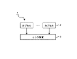
図1は、本発明に係るセンシングシステムの実施の形態1を示す図である。このセンシングシステム1は、複数個のカプセル2(以下、単にカプセルという。)、および、各カプセル2からの信号を受信するためのセンタ装置3を備える。
Embodiment 1 FIG.
FIG. 1 is a diagram showing a first embodiment of a sensing system according to the present invention. The sensing system 1 includes a plurality of capsules 2 (hereinafter simply referred to as capsules) and a center device 3 for receiving a signal from each
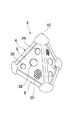
図2を参照して、カプセル2は、火災や地震などの災害時に周囲の状況を検出するためのもので、本体4内に後述する各種装置が内蔵されている。カプセル2は、災害時に、建物内に外部から投げ込まれたり、建物内部の適当な格納スペースに予め設置しておき投射装置(図示しない)が火災(熱)や揺れなどを感知すると該装置から自動的に放出されたり、建物の側壁や天井などの壁に予め取り付けておき、建物が損傷すると壁から外れて落下したりするようになっている。
With reference to FIG. 2, the
カプセル2の本体4は正四面体状で、地面などに衝突する際に4つの面6を保護するために、辺(6つ)と頂点(4つ)にはそれぞれ、保護材8,10が取り付けてある。また、取り扱い易さや安全性(投げ込まれるなどしたときに万が一被災者に当たるようなことがあっても被災者が怪我することがない)を考慮してカプセル2は小型・軽量であるのが望ましい。
The
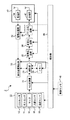
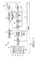
カプセル2は、図3に示すように、外界の情報を得るためのセンサ(外界情報検出手段)として、動画を撮像するCCDセンサ(カメラ)12、一酸化炭素、亜硫酸ガスなどの有毒ガスを検出するガスセンサ14、異常音を検出するマイク16、移動熱源を検出する人感センサ(焦電型赤外線センサ)18、温度センサ19、などを内蔵し、各面6には、これらセンサによるセンシングに必要な情報、例えば光、音、外気などを取り込む複数の窓20(図2)が取り付けられている。各センサは、カプセルの軽量化のため半導体式センサが好ましい。また、各センサは、4つの面6に対応して4つ分本体4内に組み込んでもよいし、1つのセンサが2つ、3つまたは全部の面6に共通するように構成してもよい。例えば、2つの面6の窓20を介して入射された光を1つのCCDセンサに入射させる曲面ミラーを2つ用いることで、組み込むCCDセンサは2つになる。
As shown in FIG. 3, the
これらセンサからなるセンサ群22は、A/D変換器24を介して、カプセル2全体を制御する制御部26に接続されており、センサ群22からのアナログ信号がA/D変換器24でディジタル信号に変換されて制御部26に送出されるようになっている。制御部26にはまた、外界情報に対応するディジタルデータを記憶するためのメモリ28、および、カプセル2の位置(3次元座標)を検出するための自己位置検出部30が接続されている。
A
自己位置検出部30には、復号化回路32を介して無線受信部34が接続されている。受信部34は、受信アンテナ、増幅器、ミキサ、復調器などから構成されており、GPS衛星、準天頂衛星、擬似衛星などの位置情報提供装置が送信する位置情報を受信するためのものである。自己位置検出部30は、復号化回路32で復号化された位置情報に基づいてカプセル2の位置を検出するようになっている。
A
制御部26にはさらに、センサ群22の各センサで得た外界のデータ(画像データや音声データ)と自己位置検出部30で検出した自己位置のデータとを符合化する符号化回路35、符号化された外界データおよび自己位置データを多重化する多重化回路36、多重化データにヘッダ、自己のアドレス、および送信先であるセンタ装置3のアドレスを付けてパケット化するパケット化回路38を介して、無線送信部40が接続されている。送信部40は、変調器、ミキサ、増幅器、送信アンテナなどから構成されており、外界データ(外界情報)および自己位置データ(自己位置情報)をセンタ装置3に送信するためのものである。受信部34と送信部40は無線送受信手段42を構成する。受信部34および送信部40のアンテナは、例えば、正四面体状本体4の頂点に位置する保護材10内に配置される(図2参照)。なお、無線送受信手段42は、アンテナを受信部34と送信部40で共通に使用するようスイッチング回路を有してもよい。
The
カプセル2の本体4内にはさらに、各構成要素(センサ群22、制御部26、自己位置検出部30、無線送受信手段42など)に通電を行うための電源部44が搭載されている。電源部44には衝撃センサ46が接続されており、投げ込まれたり放出されたり落下したりなどして壁や地面などに衝突してカプセル2が衝撃を受けると、衝撃センサ46からの検出情報が電源部44に送出され、これにより電源部44が起動するようになっている。電源部44は、被災者の避難が完了するまでカプセル2がセンシングを行えるよう、所定時間(例えば1〜数時間)各構成要素に通電を行うように構成されている。
A
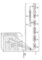
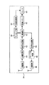
図4に示すように、センサ装置3の制御部50には、復号化回路52、次いで分離回路54を介して無線受信部58が接続されており、無線受信部58で各カプセル2から受信した多重化データは、分離回路54でヘッダに基づいて外界データ(画像データを含む)および自己位置データに分離され、次いで復号化回路52で復号化して制御部50に送出されるようにしてある。外界情報を示すデータのうち画像データは、画像メモリ62に出力され、該メモリに記憶された画像データはモニタ64に表示されるようになっている。制御部50にはさらに、分離回路54で分離された画像データ以外のデータ(音声データや温度データなど)に基づいて、外界情報を関連付けた各センシングカプセルの位置をマッピングした地図および/または各センシングカプセルの位置と外界情報との関係を示すテーブルを作成し地図記憶部66に記憶するためのマッピング部68が接続されている。地図記憶部66に記憶された地図および/またはテーブルは、画像表示用のモニタ64に表示されるようになっている。代わりに、地図やテーブルを不図示の別のモニタに表示するようにしてもよい。
As shown in FIG. 4, a
次に、かかる構成を備えたセンシングシステム1の動作を説明する。建物で火災が発生したと仮定して、複数のカプセル2が外部から建物内に投げ込まれたり建物内に設置された投射装置などにより放出されたりして壁や地面などに衝突すると、電源部44が起動し各構成要素への通電が開始される。カプセル2は、バウンドしたり地面を転がるなどした後静止する。
Next, the operation of the sensing system 1 having such a configuration will be described. Assuming that a fire has occurred in the building, when a plurality of
各カプセル2の受信部34が4つ以上の、位置情報提供装置が送信する位置情報を受信すると、自己位置検出部30は、復号化回路32で復号化された位置情報に基づいて自己位置を特定し、自己位置情報を制御部26に送出する。一方、センシングを開始したセンサ群22からのアナログ信号は、A/D変換器24でディジタル信号に変換されて制御部26に送出される。外界情報に対応するディジタルデータはメモリ28に記憶される。カプセル2は、静止した状態で、4つの面6の一つは通常地面に対向するため該面を介して外界情報を得ることができないが、(側壁付近で静止したとしても)残りの面の少なくとも一つの前方には障害物がない可能性が高く、この面を介してセンシングに必要な光などを取り込むことができる。
When the
自己位置検出部30で検出した自己位置データおよびメモリ28に記憶された外界データは、符号化回路35で符号化され、多重化回路36で多重化され、次いでパケット化回路38でヘッダ、自己のアドレス、およびセンタ装置3のアドレスを付けてパケット化され、送信部40を介してセンタ装置3に送信される。
The self-position data detected by the self-
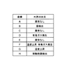
センタ装置3の受信部58は各カプセル2から信号を受信すると、分離回路54は、ヘッダに基づいて多重化データを外界データ(画像データ、音声データ、温度データなど)と自己位置データに分離し、続いて、復号化回路52は各データを復号化し、制御部50に送出する。マッピング部68は、画像データ以外の外界データおよび自己位置データに基づいて、外界の情報(例えば、異常があるか否か、あればどのような異常か)を関連付けた各センシングカプセルの位置(座標)をマッピングした地図および/または各センシングカプセルの位置と外界情報との関係を示すテーブルを作成し地図記憶部66に記憶する。図5は、そのようなテーブルの一例を示すものである。この例では、座標A,C,Eのカプセルは異常を検出せず、座標Bのカプセルはマイク16で音を検出し、座標Dのカプセルはガスセンサ14で有毒ガスを検出し、座標Gのカプセルは温度センサ19で温度上昇を検出し、座標Hのカプセルは人感センサ18で移動熱源を検出し、座標Fのカプセルは温度上昇とともに有毒ガスを検出している。モニタ64にはこのようなテーブルが表示される。このようにカプセルの位置情報と外界情報を地図やテーブルとすることで被災状況の把握がより容易になる。
When the
一方、各カプセル2から送られてきた画像データは、画像メモリ62に出力され、モニタ64に画像(動画像)が表示される。複数のカプセル2からの複数の画像が一度にモニタ64上に表示されるようにしてもよいし、あるいは、入力部(図示しない)を介したシステム1の使用者からの指令に基づいて画面が適宜切り替わるようにしてもよい。いずれにしても、モニタ64には、(各カプセル2から送信されたデータに付いた該カプセルのアドレスに基づいて)どの画像がどの地点のものかがシステム1の使用者にわかるよう各カプセルの位置と関連付けて画像が表示される(例えば、テーブルの各座標とその外界情報の横などに対応する画像を表示)必要がある。
On the other hand, the image data sent from each
本実施形態によれば、被災者の位置や通路・部屋の状態などの被災状況をリアルタイムに把握することができる。したがって、本実施形態に係るセンシングシステム1を利用すれば、進入経路や避難経路の選定を建物外にいながら行うことができ、建物内に取り残された人を迅速に救出するともに救助者の安全を確保できる。 According to the present embodiment, it is possible to grasp the disaster situation such as the position of the victim and the state of the passage / room in real time. Therefore, if the sensing system 1 according to the present embodiment is used, the entry route and the evacuation route can be selected while outside the building, and the person left in the building can be rescued quickly and the safety of the rescuer. Can be secured.
実施の形態2.
上記実施形態では、各カプセル2は、4つ以上の、位置情報提供装置が送信する位置情報を受信して自己位置を検出したが、カプセルの位置によっては1〜3つの位置情報しか受信できない、あるいは、位置情報を全く受信できない場合がある。本実施形態では、自己位置が検出できないカプセルは、他のカプセルであって位置が既に検出されたものからの位置情報を得て、自己位置の検出を行う。この目的のため、各カプセルは、図3に示すのと略同一の構成を備えるが、受信部34は、位置情報提供装置が送信する位置情報以外に他のカプセルからの信号を受信するための構成要素(受信アンテナ、増幅器、ミキサ、復調器など)をさらに備えるとともに、制御部26は、位置情報のみでは自己位置が検出できない場合に支援要求信号を作成し送信部40を介して発信させ、且つ/または、受信部34が他のカプセルから支援要求信号を受信した場合に、自己位置データを含む応答信号を作成し送信部40を介して支援要求信号を発信したカプセルに送信するようになっている。
In the above-described embodiment, each
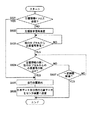
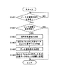
図3および図6を参照して、各カプセルの自己位置検出動作を説明する。まず、ステップS601で、いずれかのカプセル2の受信部34が受信した位置情報が4つ未満である場合、自己位置検出部30は、制御部26に対し自己位置を特定するのに十分な数の信号を受信していないことを示す信号を送出する。ステップS602で、制御部26は支援要求信号を作成する。この信号は、符号化回路35で符号化され、パケット化回路38で自己のアドレスを付けてパケット化され、送信部40を介して発信される。ステップS603で、受信部34が他のカプセルから該カプセルの自己位置データを含む応答信号を受信すると、フローはステップS604に進む。
With reference to FIG. 3 and FIG. 6, the self-position detection operation of each capsule will be described. First, in step S601, when the position information received by the receiving
ステップS604で、受信した位置情報と他のカプセルから受信した応答信号の数の合計が4つ(例えば位置情報提供装置からの位置情報が一つのみであれば、他のカプセルからの応答信号が3つ)またはそれ以上であれば、ステップS605に進み、自己位置検出部30はカプセルの位置を特定する。そして、ステップS606で、実施の形態1で説明したように、自己位置データと外界データを送信部40を介してセンタ装置3に送信し、フローは終了する。ステップS604で、位置情報提供装置から受信した位置情報と他のカプセルから受信した応答信号の数の合計が4未満であれば、ステップS607に進み、支援要求信号発信から一定時間経過するまで上記合計数が4つになるまで待機するが、一定時間経過しても合計数が4つにならない場合は、このカプセルに関しては自己位置が検出できないとしてフローは終了する。
In step S604, the total of the received position information and the number of response signals received from other capsules is four (for example, if there is only one position information from the position information providing apparatus, the response signals from other capsules are If three or more, the process proceeds to step S605, and the self-
ステップS601で、受信部34が受信した位置情報が4つ以上の場合、ステップS605に進み、自己位置検出部30はカプセルの位置を特定する。
If the position information received by the receiving
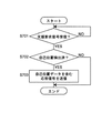
図7は、自己位置が検出できないカプセルからの支援要求信号を受けるカプセル側の動作を示すフローチャートである。図3も参照して、ステップS701で受信部34が支援要求信号を受信すると、ステップS702で、自己位置検出部30は、既に自己の位置を検出しているか否かを示す信号を制御部26に送出する。既に検出していれば、ステップS703で、制御部26は、自己位置データを含む応答信号を作成する。この信号は、符号化回路35で符号化され、パケット化回路38で送信先のアドレスを付してパケット化され、送信部40を介して自己位置が検出できないカプセルに送信される。その後フローは終了する。
FIG. 7 is a flowchart showing an operation on the capsule side that receives a support request signal from a capsule whose self-position cannot be detected. Referring also to FIG. 3, when the receiving
ステップS702で自己位置が検出されていなければ、応答信号を送信せずフローは終了する。 If the self position is not detected in step S702, a response signal is not transmitted and the flow ends.
本実施形態によれば、いずれかのカプセルがGPS衛星などの位置情報提供装置から十分な強度の信号が得られない場合に、十分な強度の信号が得られる他のカプセルを利用することで、上記いずれかのカプセルの位置を検出することが可能である。このように、カプセルが投げ込まれるなどして位置情報提供装置からの信号の届きにくい位置に静止することになっても自己の位置を検出できるので、システム(センタ装置)の使用者にできるだけ多くの地点の情報を与えることができる。 According to this embodiment, when any capsule cannot obtain a signal with sufficient strength from a position information providing device such as a GPS satellite, by using another capsule that can obtain a signal with sufficient strength, It is possible to detect the position of any of the above capsules. In this way, even if the capsule is thrown into the position where the signal from the position information providing device is difficult to reach, it is possible to detect its own position, so as many users as possible to the system (center device) You can give point information.
実施の形態3.
上記実施形態では、各カプセルからの外界データおよび自己位置データはセンタ装置に直接送信されるとして説明したが、カプセルの位置によっては遮蔽物などによりセンタ装置に上記データを直接送信できない場合がある。本実施形態に係るセンシングシステムでは、図8に示すように、各カプセル2aは、直接データをセンタ装置に送信できない場合に、他のカプセルのいずれかを介してあるいはデータを無線送受信する基地局80のいずれかを介してセンタ装置3aにデータを送信する機能を備えている。説明の便宜上、以下では、外界データおよび自己位置データを送信するカプセル2aをカプセル#0、他の複数のカプセル2aをカプセル#1〜カプセル#n、複数の基地局80を基地局##1〜##3と適宜呼ぶことにする。
Embodiment 3 FIG.
In the above embodiment, it has been described that the external environment data and the self-position data from each capsule are directly transmitted to the center apparatus. However, depending on the position of the capsule, the data may not be directly transmitted to the center apparatus due to a shield or the like. In the sensing system according to the present embodiment, as shown in FIG. 8, each
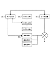
図9は、各カプセル2aの構成を示す。カプセル2aは、実施の形態1,2のカプセル2(図3)と類似しているが、センタ装置3a、他のカプセル、または基地局80にデータ送信要求信号(情報送信要求信号)を送信するとともに、該信号を受け取ったセンタ装置3a、他のカプセル、または基地局80から受取通知信号を受信したり他のカプセルから外界データおよび自己位置データを受信するようになっている。
FIG. 9 shows the configuration of each
具体的に、各カプセル2aの受信部34aは、位置情報提供装置の位置情報以外に、センタ装置3a、他のカプセル、または基地局80からの受取通知信号並びに他のカプセルからの外界データおよび自己位置データを受信するための構成要素(受信アンテナ、増幅器、ミキサ、復調器など)をさらに備える。カプセル2aはまた、受取通知信号並びに他のカプセルからの外界データおよび自己位置データを復号化して制御部26に出力するための復号化回路82を備える。制御部26は、データ送信要求信号を作成して送信部40を介して発信させたり、受信部34aが他のカプセルからデータ送信要求信号を受信した場合に、受取通知信号を作成し送信部40を介してデータ送信要求信号を発したカプセルに送信するようになっている。
Specifically, the receiving unit 34a of each
一方、センタ装置3aは、図4のセンタ装置3に類似した図10に示す構成を有する。制御部50は、受信部58がいずれかのカプセルからデータ送信要求信号を受信すると受取通知信号を作成するようになっている。制御部50には、受取通知信号を符号化する符号化回路84と、符号化された受取通知信号にセンタ装置3aのアドレスおよび送信先である上記いずれかのカプセルのアドレスを付けてパケット化するパケット化回路86とを介して、無線送信部88が接続されている。
On the other hand, the
また、基地局80は、図11に示すように、基地局全体を制御し受取通知信号を作成する制御部90と、いずれかのカプセルからのデータ送信要求信号を受信するための(受信アンテナ、増幅器、ミキサ、復調器などを含む)無線受信部92と、受信部92で受信した送信要求信号を復号化する復号化回路94と、制御部90で作成した受取通知信号を符号化する符号化回路96と、受取通知信号に自己のアドレスおよび相手先である上記いずれかのカプセルのアドレスを付してパケット化するパケット化回路98と、パケット化した受取通知信号を上記カプセルに送信するための(変調器、ミキサ、増幅器、送信アンテナなどを含む)無線送信部100とを備える。受信部92と送信部100は、基地局80の無線送受信手段を構成する。
Further, as shown in FIG. 11, the
受信部92はさらに、カプセルから送信された外界データおよび自己位置データを受信するようになっており、これらのデータはメモリ102に一時的に記憶されるようにしてある。メモリ102に記憶されたデータは、パケット化回路98でセンタ装置3aのアドレスを付けてパケット化され、次いで送信部100を介して有線または無線のネットワーク(例えばインターネット)Nを介してセンタ装置3aに送信されるようになっている。なお、カプセルから送信された外界データおよび自己位置データは、復号化回路94で復号化し符号化回路96で符号化してもよい。
The receiving
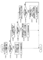
かかる構成を備えたセンシングシステムのカプセル2aの外界データおよび自己位置データの送信動作を、図8〜11とともに図12のフローチャートを用いて説明する。
The operation of transmitting the external data and the self-position data of the
まず、ステップS1201で、カプセル#0の制御部26はデータ送信要求信号を作成する。この信号は、符号化回路35で符号化され、次いでパケット化回路38で自己のアドレスとセンタ装置3aのアドレスを付けてパケット化された後、送信部40を介して送信される。ステップS1202で、受信部34aがセンタ装置3aから受取通知信号を受信すると、該信号は復号化回路82で復号化されて制御部26に送出される。ステップS1203で、外界データおよび自己位置データは、符号化回路35で符号化され、多重化回路36で多重化され、続いてパケット回路38でヘッダ、自己のアドレス、およびセンタ装置3aのアドレスを付けてパケット化され、送信部40を介してセンタ装置3aに送信される。その後、ステップS1204でセンタ装置3aからデータの受取通知信号を受信すると、フローは終了する。
First, in step S1201, the
ステップS1202で、センタ装置3aから応答がない場合、ステップS1205に進み、制御部26は再度データ送信要求信号を作成する。この信号は、符号化回路35で符号化され、次いでパケット化回路38で自己のアドレスと全ての基地局##1〜##3に共通のアドレスを付けてパケット化された後、送信部40を介して送信される。ステップS1206で、受信部34aがいずれかの基地局、例えば基地局##1から受取通知信号を受信すると、該信号は復号化回路82で復号化されて制御部26に送出される。ステップS1207で、外界データおよび自己位置データは、符号化回路35で符号化され、多重化回路36で多重化され、続いてパケット回路38でヘッダ、自己のアドレス、および基地局##1のアドレスを付けてパケット化され、送信部40を介して基地局##1に送信される。その後、ステップS1208で基地局##1からデータの受取通知信号を受信すると、フローは終了する。なお、複数の基地局から受取通知信号を受信した場合、いずれの基地局に外界データおよび自己位置データを送信するかは、何らかの法則で決めるようにすればよい。
If there is no response from the
ステップS1206で、いずれの基地局##1〜##3からも応答がない場合、ステップS1209に進み、制御部26は再度データ送信要求信号を作成する。この信号は、符号化回路35で符号化され、次いでパケット化回路38で自己のアドレスと全てのカプセル#1〜#nに共通のアドレスを付けてパケット化された後、送信部40を介して送信される。ステップS1210で、受信部34aがいずれかのカプセル、例えばカプセル##5から受取通知信号を受信すると、該信号は復号化回路82で復号化されて制御部26に送出される。ステップS1211で、外界データおよび自己位置データは、符号化回路35で符号化され、多重化回路36で多重化され、続いてパケット回路38でヘッダ、自己のアドレス、およびカプセル#5のアドレスを付けてパケット化された後、送信部40を介してカプセル#5に送信される。その後、ステップS1212でカプセル#5からデータの受取通知信号を受信すると、フローは終了する。なお、複数のカプセルから受取通知信号を受信した場合、いずれのカプセルに外界データおよび自己位置データを送信するかは、何らかの法則で決めるようにすればよい。
If there is no response from any of the base stations ## 1 to ## 3 in step S1206, the process proceeds to step S1209, and the
ステップS1210いずれのカプセル#1〜#nからも応答がない場合、カプセル#0に関してはデータを送信できないとしてフローを終了する。 If there is no response from any of the capsules # 1 to #n in step S1210, it is determined that data cannot be transmitted for the capsule # 0, and the flow ends.
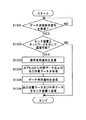
図13は、カプセル#0からのデータ送信要求を受ける基地局側の動作の一例を示すフローチャートである。図11も参照してステップS1301で基地局80の受信部92がデータ送信要求信号を受信すると、該信号は復号化回路94で復号化されて制御部90に送出される。ステップS1302で、制御部90は、基地局80がネットワークNを介してセンタ装置と通信可能な状態にあるか否かを確認する。具体的には、制御部90でセンタ装置3aに対する接続要求信号を作成し、該信号を符号化回路96で符号化し、パケット化回路98で基地局80のアドレスとセンタ装置3aのアドレスを付けてパケット化し、送信部100を介してセンタ装置3aに送信する。図10を参照して、センタ装置3aが接続要求信号を受け付けると、カプセルからのデータ送信要求信号の場合と同様にして、応答信号を基地局80に送信する。
FIG. 13 is a flowchart showing an example of an operation on the base station side that receives a data transmission request from capsule # 0. Referring also to FIG. 11, when the receiving
ステップS1302で、基地局80がセンタ装置3aと通信可能であれば、ステップS1303に進み、制御部90は受取通知信号を作成する。この信号は、符号化回路96で符号化され、パケット化回路98でカプセル#0のアドレスと自己のアドレスを付けてパケット化され、送信部100を介してカプセル#0に送信される。通信可能でなければ、カプセル#0に対し応答せずそのままフローは終了する。
If the
ステップS1304で、カプセル#0から受信部92が外界データおよび自己位置データを受信すると、これらのデータはメモリ102に一時的に記憶される。ステップS1305で、制御部90はデータ受取通知信号を作成する。この信号は、符号化回路96で符号化され、パケット化回路98でカプセル#0のアドレスと自己のアドレスを付けてパケット化され、送信部100を介してカプセル#0に送信される。
In step S1304, when the receiving
ステップS1306で、メモリ102に記憶された外界データおよび自己位置データは、パケット化回路98でカプセル#0のアドレスとセンタ装置3aのアドレスを付けてパケット化され、送信部100からネットワークNを介してセンタ装置3aに送信される。その後フローは終了する。
In
図14は、カプセル#0からのデータ送信要求を受けるカプセル#5側の動作の一例を示すフローチャートである。図9も参照してステップS1401でカプセル#5の受信部34aがデータ送信要求信号を受信すると、該信号は復号化回路82で復号化されて制御部26に送出される。ステップS1402で、制御部26は、既にカプセル#5がセンタ装置3aに外界データおよび自己位置データを送信済みか否かに基づいて、カプセル#5がセンタ装置3aと通信可能な状態にあるか否かを確認する。カプセル5#の自己位置データ等のセンタ装置3aへの送信は、直接の場合以外に、さらに別のカプセルを介する場合、基地局80次いでネットワークNを介する場合が考えられる。
FIG. 14 is a flowchart showing an example of the operation on the capsule # 5 side that receives the data transmission request from the capsule # 0. Referring also to FIG. 9, when the reception unit 34a of the capsule # 5 receives the data transmission request signal in step S1401, the signal is decoded by the
ステップS1402で、カプセル#5がセンタ装置3aと通信可能であれば、ステップS1403に進み、制御部26は受取通知信号を作成する。この信号は、符号化回路35で符号化され、パケット化回路38でカプセル#0のアドレスと自己のアドレスを付けてパケット化され、送信部40を介してカプセル#0に送信される。通信可能でなければ、カプセル#0に対し応答せずそのままフローは終了する。
If capsule # 5 can communicate with the
ステップS1404で、カプセル#0から受信部34aが外界データおよび(自己)位置データを受信すると、これらのデータは復号化回路82で復号化されメモリ28に一時的に記憶される。ステップS1405で、制御部26はデータ受取通知信号を作成する。この信号は、符号化回路35で符号化され、パケット化回路38でカプセル#0のアドレスと自己のアドレスを付けてパケット化され、送信部40を介してカプセル#0に送信される。
In step S1404, when the receiving unit 34a receives external world data and (self) position data from the capsule # 0, these data are decoded by the
ステップS1406で、メモリ28に記憶されたカプセル#0の位置データおよび外界データは、メモリに記憶された自己(カプセル#5)の位置データおよび外界データとともに、符号化回路35で符号化され、多重化回路36で多重化され、パケット化回路38でヘッダ、カプセル#0、カプセル#5、およびセンタ装置3aのアドレスを付けてパケット化され、送信部40を介してセンタ装置3aに送信される。その後フローは終了する。但し、カプセル#5が直接センタ装置3aと通信できる位置にない場合、データは、さらに別のカプセルを介してあるいは基地局80次いでネットワークNを介して、センタ装置3aに送信される。
In step S1406, the position data and outside world data of capsule # 0 stored in the
本実施形態によれば、カプセル#0がセンタ装置3aに対し外界データおよび自己位置データを直接送信できない場合でも、基地局#1や他のカプセル#5を介してセンタ装置3aに上記データを送信できる。このように、カプセルが投げ込まれるなどしてセンタ装置と直接通信しにくい位置に静止することになっても、該カプセルの外界データおよび自己位置データを得ることができるので、システム(センタ装置)の使用者にできるだけ多くの情報を与えることができる。
According to the present embodiment, even when the capsule # 0 cannot directly transmit the external data and the self-location data to the
以上、本発明に係る具体的な実施形態について説明したが、本発明はこれらに限らず種々改変可能である。例えば、上記実施形態では、カプセル2の本体4は正四面体を基本とした形状を有するが、多面体であれば正多面体に限らない。また、カプセル本体は多面体の代わりに球体を基本した形状を有してもよい。
Although specific embodiments according to the present invention have been described above, the present invention is not limited to these and can be variously modified. For example, in the above embodiment, the
また、正四面体などの多面体の全ての面でなく2つ以上の面を介して外界情報を得ることができるように構成されたカプセルも本発明の範囲内に含まれる。この場合、カプセルが静止すると、外界情報を得る面以外の面が地面に対向するようカプセルの重心を調整するのが好ましい。 In addition, capsules configured so that external information can be obtained through two or more faces instead of all faces of a polyhedron such as a regular tetrahedron are also included in the scope of the present invention. In this case, when the capsule is stationary, it is preferable to adjust the center of gravity of the capsule so that a surface other than the surface from which external information is obtained faces the ground.
さらに、センシングシステムに用いられるカプセル全てが、本体が多面体状あるいは球状でなくてもよい。すなわち、一つまたはそれ以上のカプセルを建物などに埋め込めておき、これらカプセルが災害時に投げ込まれるなどしたカプセルとともにセンシングシステムを構成する場合も本発明の範囲内に含まれる。この場合、建物に埋め込まれたカプセルは既にその位置は固定されているので、位置情報提供装置からの位置情報を受信して自己位置を検出する必要はない。 Further, all capsules used in the sensing system may not have a polyhedral or spherical body. That is, the case where one or more capsules are embedded in a building or the like, and the sensing system is configured with capsules that are thrown in a disaster is also included in the scope of the present invention. In this case, since the position of the capsule embedded in the building is already fixed, there is no need to receive the position information from the position information providing device and detect its own position.
加えて、実施の形態2において、自己位置を検出するために位置情報提供装置からの位置情報および/または他のカプセルの位置データを受信するアンテナは、1つである必要はない。例えば受信アンテナを3つ以上設けておけば、自己位置を検出できないカプセルは、自己位置を検出済みの他のカプセルの一つから該カプセルの位置データを受信するとともに、該カプセルから3つ以上のアンテナで信号を受信し、各アンテナに到達する電波の時間差から三角測量の原理で上記他のカプセルの方位および距離を算出することができ、その結果、自己位置を検出できる。これに関し、図6のフローチャートのステップS607において、一定時間経過しても合計数が4つにならない場合、自己位置を検出済みの他のカプセルの一つから信号を3つ以上のアンテナで受信することにより、自己位置を検出するようにしてもよい。 In addition, in the second embodiment, it is not necessary to have one antenna that receives position information from the position information providing apparatus and / or position data of other capsules in order to detect the self position. For example, if three or more receiving antennas are provided, a capsule whose self-position cannot be detected receives position data of the capsule from one of the other capsules whose self-position has been detected, and three or more capsules from the capsule. The signals can be received by the antennas, and the azimuth and distance of the other capsules can be calculated from the time difference between the radio waves reaching the respective antennas based on the principle of triangulation. In this regard, in step S607 of the flowchart of FIG. 6, if the total number does not reach four even after a certain time has elapsed, a signal is received from one of the other capsules whose self-position has been detected by three or more antennas. Thus, the self position may be detected.
なお、カプセルの使用箇所は建物内に限らず屋外でもよい。例えば、災害が大規模であれば、無人または有人の航空機を用いてカプセルを上空から散布するようにしてもよい。 In addition, the place where the capsule is used is not limited to the inside of the building but may be outdoors. For example, if the disaster is large, the capsule may be sprayed from above using an unmanned or manned aircraft.
1 センシングシステム
2 センシングカプセル
4 カプセル本体
6 カプセル本体の面
DESCRIPTION OF SYMBOLS 1
Claims (13)
各センシングカプセルの無線送受信手段は、外界情報および/または自己位置情報を他のセンシングカプセルに対し送信可能、並びに/若しくは、他のセンシングカプセルからの外界情報および/または自己位置情報を受信可能に構成されていることを特徴とするセンシングシステム。 At least one external information detecting means for obtaining external information, self-position detecting means for detecting self-position, wireless transmission / reception means for transmitting external information and self-position information, external information detecting means, self-position detecting means, And a plurality of sensing capsules housed in a polyhedral or spherical main body, and a power supply for supplying power to the wireless transceiver means,
The wireless transmission / reception means of each sensing capsule is configured to be able to transmit outside world information and / or self-position information to other sensing capsules and / or to receive outside world information and / or self-position information from other sensing capsules. Sensing system characterized by being.
自己位置が検出された他のセンシングカプセルの無線送受信手段は、上記支援要求信号を受信すると自己位置情報を上記いずれかのセンシングカプセルに送信することを特徴とする請求項6記載のセンシングシステム。 If the self-position detecting means of any sensing capsule cannot detect the self-position based only on the position information transmitted by the position information providing device, the wireless transmitting / receiving means transmits a support request signal,
7. The sensing system according to claim 6, wherein the wireless transmission / reception means of another sensing capsule in which the self-position is detected transmits the self-position information to any one of the sensing capsules when receiving the support request signal.
センタ装置と通信可能な他のセンシングカプセルの無線送受信手段は、上記情報送信要求信号を受信した場合、上記いずれかのセンシングカプセルに対し受取通知信号を送信し、
上記いずれかのセンシングカプセルの無線送受信手段は、上記受取通知信号を受信すると、上記他のセンシングカプセルに対し上記いずれかのセンシングカプセルの外界情報および自己位置情報を送信することを特徴とする請求項8記載のセンシングシステム。 When the wireless transmission / reception means of any sensing capsule cannot directly transmit the outside world information and the self-location information to the center device, an information transmission request signal is transmitted,
When the wireless transmission / reception means of another sensing capsule capable of communicating with the center device receives the information transmission request signal, it transmits a reception notification signal to any of the sensing capsules,
The wireless transmission / reception means of any one of the sensing capsules, when receiving the reception notification signal, transmits the external information and the self-location information of any of the sensing capsules to the other sensing capsule. 8. The sensing system according to 8.
いずれかのセンシングカプセルの無線送受信手段が外界情報および自己位置情報をセンタ装置に直接送信できない場合、情報送信要求信号を発信し、
基地局の無線送受信手段は、上記情報送信要求信号を受信した場合、上記いずれかのセンシングカプセルに対し受取通知信号を送信し、
上記いずれかのセンシングカプセルの無線送受信手段は、上記受取通知信号を受信すると、基地局に対し外界情報および自己位置情報を送信することを特徴とする請求項8記載のセンシングシステム。 A base station having wireless transmission / reception means and capable of communicating with the center apparatus;
When the wireless transmission / reception means of any sensing capsule cannot directly transmit the outside world information and the self-location information to the center device, an information transmission request signal is transmitted,
When the wireless transmission / reception means of the base station receives the information transmission request signal, it transmits a reception notification signal to any of the sensing capsules,
9. The sensing system according to claim 8, wherein the wireless transmission / reception means of any one of the sensing capsules transmits the outside world information and the self-location information to the base station when receiving the reception notification signal.
各センシングカプセルの外界情報および自己位置情報を受信するセンタ装置と、
を備えたセンシングシステム。 At least one external information detecting means for obtaining external information, self-position detecting means for detecting self-position, wireless transmission / reception means for transmitting external information and self-position information, external information detecting means, self-position detecting means, And a plurality of sensing capsules containing a power supply unit for supplying power to the wireless transmission / reception means, and a polyhedral or spherical body,
A center device that receives external information and self-location information of each sensing capsule;
Sensing system equipped with.
Based on the received external environment information and self-location information of each sensing capsule, the center device maps the position of each sensing capsule associated with the external environment information and / or the relationship between the position of each sensing capsule and external environment information. The sensing system according to any one of claims 8 to 12, wherein a table indicating the above is created.
Priority Applications (1)
| Application Number | Priority Date | Filing Date | Title |
|---|---|---|---|
| JP2004103820A JP2005292951A (en) | 2004-03-31 | 2004-03-31 | Sensing capsule and sensing system |
Applications Claiming Priority (1)
| Application Number | Priority Date | Filing Date | Title |
|---|---|---|---|
| JP2004103820A JP2005292951A (en) | 2004-03-31 | 2004-03-31 | Sensing capsule and sensing system |
Publications (1)
| Publication Number | Publication Date |
|---|---|
| JP2005292951A true JP2005292951A (en) | 2005-10-20 |
Family
ID=35325850
Family Applications (1)
| Application Number | Title | Priority Date | Filing Date |
|---|---|---|---|
| JP2004103820A Pending JP2005292951A (en) | 2004-03-31 | 2004-03-31 | Sensing capsule and sensing system |
Country Status (1)
| Country | Link |
|---|---|
| JP (1) | JP2005292951A (en) |
Cited By (1)
| Publication number | Priority date | Publication date | Assignee | Title |
|---|---|---|---|---|
| JP2019520546A (en) * | 2017-06-05 | 2019-07-18 | 中国▲鉱▼▲業▼大学 | Wireless sensor node with graded protection structure |
-
2004
- 2004-03-31 JP JP2004103820A patent/JP2005292951A/en active Pending
Cited By (1)
| Publication number | Priority date | Publication date | Assignee | Title |
|---|---|---|---|---|
| JP2019520546A (en) * | 2017-06-05 | 2019-07-18 | 中国▲鉱▼▲業▼大学 | Wireless sensor node with graded protection structure |
Similar Documents
| Publication | Publication Date | Title |
|---|---|---|
| US10536528B2 (en) | Communications network for emergency services personnel | |
| KR101589133B1 (en) | Disaster rescue system using Disaster rescue robot | |
| US7652571B2 (en) | Graphical user interface for emergency apparatus and method for operating same | |
| US7263379B1 (en) | Communications network for emergency services personnel | |
| US10930129B2 (en) | Self-propelled monitoring device | |
| US11647375B2 (en) | Providing responders with relevant real-time information | |
| JP2012531665A (en) | Video surveillance system | |
| WO2018043284A1 (en) | Base station device, emergency alert notification system, and emergency alert notification method | |
| CN205611878U (en) | Multifunctional fire fighting helmet | |
| TW202137154A (en) | Emergency power positioning system | |
| JP2017021559A (en) | Terminal device, management device, radio communication system, and photographic image display method | |
| JPH11250377A (en) | Portable type safety system | |
| KR20170111767A (en) | Robot for disaster scene | |
| KR102503849B1 (en) | Mobile Base Station and System for Providing Services Using Mobile Base Station | |
| KR101356738B1 (en) | Breathing apparatus for emergency | |
| JP2005292951A (en) | Sensing capsule and sensing system | |
| KR102661212B1 (en) | Firefighting drone with thermal imaging camera | |
| CN111792029A (en) | Autonomous aircraft for ventilating and supplying oxygen to people | |
| KR20230129092A (en) | Remote imaging device and fire detection system using the same | |
| CN207850428U (en) | A kind of ad hoc network command terminal system of fire fighter's vital sign monitoring | |
| KR20210147418A (en) | The multi transmission system for drone | |
| JP3924620B2 (en) | Rolling distributed search unit | |
| KR101707906B1 (en) | Emergency call device and system | |
| US10212758B2 (en) | Communication terminal device, communication system, and communication method used by workers undertaking dangerous operations | |
| CN207051741U (en) | A kind of unmanned machine equipment of honeycomb rescue type |
Legal Events
| Date | Code | Title | Description |
|---|---|---|---|
| A621 | Written request for application examination |
Free format text: JAPANESE INTERMEDIATE CODE: A621 Effective date: 20051117 |
|
| A977 | Report on retrieval |
Free format text: JAPANESE INTERMEDIATE CODE: A971007 Effective date: 20080220 |
|
| A131 | Notification of reasons for refusal |
Free format text: JAPANESE INTERMEDIATE CODE: A131 Effective date: 20080311 |
|
| A521 | Written amendment |
Free format text: JAPANESE INTERMEDIATE CODE: A523 Effective date: 20080509 |
|
| RD03 | Notification of appointment of power of attorney |
Free format text: JAPANESE INTERMEDIATE CODE: A7423 Effective date: 20080509 |
|
| A131 | Notification of reasons for refusal |
Free format text: JAPANESE INTERMEDIATE CODE: A131 Effective date: 20080826 |
|
| A02 | Decision of refusal |
Free format text: JAPANESE INTERMEDIATE CODE: A02 Effective date: 20090106 |