JP2005292882A - Image correction processing system - Google Patents
Image correction processing system Download PDFInfo
- Publication number
- JP2005292882A JP2005292882A JP2004102566A JP2004102566A JP2005292882A JP 2005292882 A JP2005292882 A JP 2005292882A JP 2004102566 A JP2004102566 A JP 2004102566A JP 2004102566 A JP2004102566 A JP 2004102566A JP 2005292882 A JP2005292882 A JP 2005292882A
- Authority
- JP
- Japan
- Prior art keywords
- satellite
- image data
- point
- vector
- correction processing
- Prior art date
- Legal status (The legal status is an assumption and is not a legal conclusion. Google has not performed a legal analysis and makes no representation as to the accuracy of the status listed.)
- Withdrawn
Links
- 238000012545 processing Methods 0.000 title claims abstract description 113
- 238000003702 image correction Methods 0.000 title claims abstract description 50
- 238000012937 correction Methods 0.000 claims abstract description 85
- 238000000034 method Methods 0.000 claims description 46
- 230000006870 function Effects 0.000 description 32
- 238000010586 diagram Methods 0.000 description 28
- 238000003384 imaging method Methods 0.000 description 8
- 238000005259 measurement Methods 0.000 description 5
- 238000006073 displacement reaction Methods 0.000 description 2
- 240000004050 Pentaglottis sempervirens Species 0.000 description 1
- 235000004522 Pentaglottis sempervirens Nutrition 0.000 description 1
- 238000013459 approach Methods 0.000 description 1
- 238000006243 chemical reaction Methods 0.000 description 1
- 230000000694 effects Effects 0.000 description 1
- 230000003287 optical effect Effects 0.000 description 1
- 238000003672 processing method Methods 0.000 description 1
Images
Landscapes
- Image Processing (AREA)
- Image Analysis (AREA)
Abstract
Description
本発明は、人工衛星で撮像した画像データの幾何学的な歪みを補正する画像補正処理システムに関する。更に詳細には、人工衛星で撮像した画像に対して補正処理を行った幾何学補正済み画像データに対して、地表の起伏に起因する歪みを補正するオルソ補正処理を行う際に用いる画像補正処理システムに関する。
The present invention relates to an image correction processing system that corrects geometric distortion of image data captured by an artificial satellite. More specifically, image correction processing used when performing ortho correction processing for correcting distortion caused by the undulation of the ground surface for geometrically corrected image data obtained by performing correction processing on an image captured by an artificial satellite. About the system.
人工衛星で地表(本明細書に於いて地表とは、陸地のみならず海面をも含むとする)を撮像した場合、地球の自転や湾曲、人工衛星の姿勢変化等による影響が生じる他、地表の起伏に起因する歪みが発生している。 When imaging the earth's surface (in this specification, the earth's surface includes not only the land but also the sea surface) with an artificial satellite, the effects of the rotation and curvature of the earth, changes in the attitude of the satellite, etc. Distortion caused by the undulations of
その為、単に人工衛星で撮像した画像データをそのまま使用するのではなく、上述の影響や歪みを補正した後の画像データを使用することが多い。 For this reason, image data captured by an artificial satellite is not used as it is, but image data after correcting the above-described influence and distortion is often used.
通常、(1)ある地点について、撮像された画素位置と人工衛星で撮像した画像データの投影面上での位置を対応づける処理を行い、(2)その地点の投影面からの高さによって生じる正射投影に対する投影位置誤差を補正する処理、の2つの処理を行っている。 Usually, (1) for a certain point, a process of associating the imaged pixel position with the position on the projection plane of the image data imaged by the artificial satellite is performed, and (2) it occurs depending on the height of the point from the projection plane. Two processes of correcting the projection position error with respect to the orthographic projection are performed.
(1)の処理は、人工衛星のセンサモデル、軌道情報、姿勢情報等を用いた一般的にシステム補正処理又はバルク補正処理と呼ばれる補正処理、或いはGCP(Ground Control Point、地上基準点。衛星等の画像の幾何補正の為に用いられる画像と地図の双方で位置が特定出来る点)を用いて平面上での位置を補正する精密幾何補正により実現される。本明細書では、この補正処理を総称して幾何学補正処理という。幾何学補正処理とは、システム補正処理や精密幾何補正処理等のように、投影面上で平面位置を合わせる幾何学補正処理である。 The process (1) is a correction process generally referred to as a system correction process or a bulk correction process using a sensor model of an artificial satellite, orbit information, attitude information, or the like, or a GCP (Ground Control Point, a ground reference point, a satellite, etc. This is realized by precise geometric correction in which the position on the plane is corrected using a point that can be specified by both the image and the map used for geometric correction of the image. In the present specification, this correction processing is collectively referred to as geometric correction processing. The geometric correction process is a geometric correction process for aligning a plane position on the projection plane, such as a system correction process or a precise geometric correction process.
(2)の処理は、一般的にオルソ補正処理と呼ばれる、対象地点の高さ、人工衛星の仰角、方位角を用いた補正処理により実現される。 The process (2) is realized by a correction process using the height of the target point, the elevation angle of the artificial satellite, and the azimuth angle, generally called an ortho correction process.
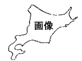
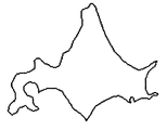
例えば人工衛星で撮像した北海道の画像データは図3に示すように歪みが発生している。そこで、図3の画像データに対して幾何学補正処理を施すことによって、図4又は図5の幾何学補正済み画像データを得ることが出来る。図4は幾何学補正処理のうちの、システム補正処理を施した場合の画像データであり、図5は幾何学補正処理のうちの、GCPを用いた精密幾何補正処理を施した場合の画像データである。尚、本明細書に於いて、幾何学補正済みデータとは、撮像された対象物(地物)が全て画像の投影面上にあるとの仮定の下で幾何学補正処理が行われた画像データを指す。即ち、ここでいう幾何学補正済み画像データに於いては、真に画像の投影面上にある対象物(地物)は正射投影位置と同じ位置に投影されているが、投影面からの高さをもつ対象物(地物)は、その高さ及び人工衛星との位置関係に応じて正射投影位置とは異なる位置に投影されている。 For example, image data of Hokkaido taken by an artificial satellite is distorted as shown in FIG. Therefore, the geometrically corrected image data shown in FIG. 4 or 5 can be obtained by performing geometric correction processing on the image data shown in FIG. FIG. 4 shows image data when the system correction process is performed in the geometric correction process, and FIG. 5 shows image data when the precise geometric correction process using GCP is performed in the geometric correction process. It is. In the present specification, the geometrically corrected data is an image that has been subjected to geometric correction processing under the assumption that all the captured objects (features) are on the projection plane of the image. Refers to data. That is, in the geometrically corrected image data here, the object (feature) that is truly on the projection plane of the image is projected at the same position as the orthographic projection position. An object (feature) having a height is projected at a position different from the orthographic projection position in accordance with the height and the positional relationship with the artificial satellite.
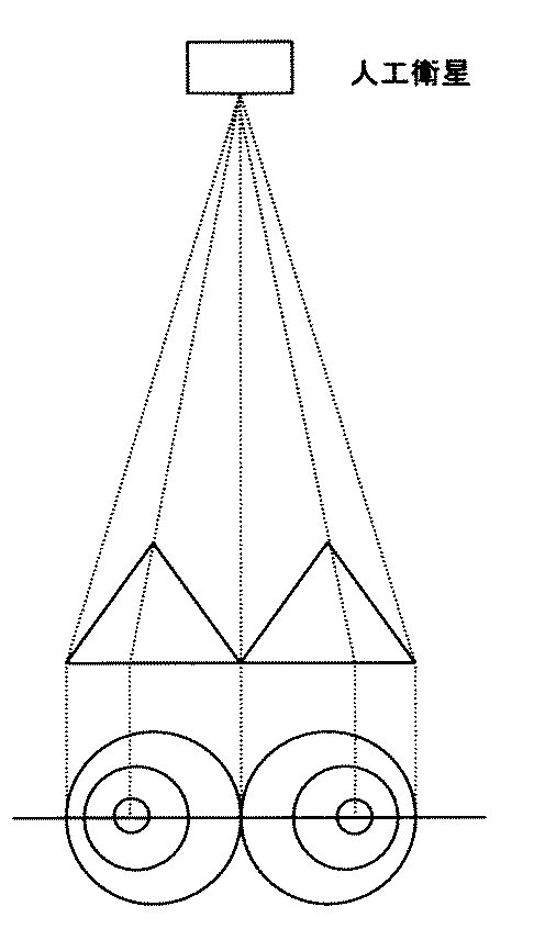
起伏のある地表、例えばある山を人工衛星で撮像した場合、その山の頂上の真上から撮像できれば何ら問題がないが、図6に示すように、通常は、頂上の真上以外のある角度を有する地点から山の撮像を行うこととなる。そうすると、人工衛星で撮像した画像データは、山の頂上が歪んで表示されることとなる。 When an undulating ground surface, for example, a certain mountain is imaged with an artificial satellite, there is no problem as long as it can be imaged from directly above the top of the mountain. However, as shown in FIG. The mountain is picked up from a point having. Then, the image data captured by the artificial satellite is displayed with the top of the mountain distorted.
従って、より正確な画像データが必要とされる場合、上記の(1)及び(2)の2つの補正処理を実行する必要がある。 Therefore, when more accurate image data is required, it is necessary to execute the above two correction processes (1) and (2).
オルソ補正処理を実行するには、対象地点から見た人工衛星の衛星仰角、衛星方位角、撮像した画像の投影面から対象地点までの高さのデータが必要となる。しかし補正済みの、つまり(1)の幾何学補正処理を行った画像データでは、撮像した画像の投影面から対象地点までの高さは、画像データに付属している投影面の高さの情報と、公表されている標高データ等を用いれば分かるが、それ以外の対象地点から見た人工衛星の衛星仰角、衛星方位角については分からない。何故ならば、幾何学補正済みの画像データでは、通常、軌道情報や姿勢情報が保持されておらず、又、幾何学補正処理を行ったことにより、画像データの画素の配列も撮像時とは異なっている為、人工衛星の衛星位置と画素の位置との対応も単純ではないからである。 In order to execute the ortho correction process, the satellite elevation angle, the satellite azimuth angle, and the height data from the projected plane of the captured image to the target point viewed from the target point are required. However, in the corrected image data, that is, in the image data subjected to the geometric correction process (1), the height from the projection plane of the captured image to the target point is the height information of the projection plane attached to the image data. However, the satellite elevation angle and satellite azimuth of the artificial satellite viewed from other target points are unknown. This is because the geometrically corrected image data usually does not hold trajectory information or posture information, and the geometric correction processing has made the pixel arrangement of the image data different from that at the time of imaging. This is because the difference between the satellite positions of the artificial satellites and the pixel positions is not simple.
そのような場合に適用可能な方法として最も簡便なのは、幾何学補正済み画像データに付属する、撮像時の人工衛星の衛星仰角、衛星方位角の平均値を全画素に対して適用する方法である。又最近では、下記非特許文献1に示すように、高分解能衛星データに対して、RPC(Rational Polynominal Camera)モデルが利用されるようになってきている。RPCモデルは、対象空間上での位置(緯度、経度、高度)と画像空間上での位置(ライン、ピクセル)を対応づけるモデルで、高次多項式で構成されており、その式の係数は、衛星データ1製品毎に衛星データの提供者から提供される。
The simplest method that can be applied in such a case is a method in which the average value of the satellite elevation angle and satellite azimuth of the satellite at the time of imaging attached to the geometrically corrected image data is applied to all pixels. . Recently, as shown in Non-Patent
しかし、解像度が高く、又衛星仰角が小さい画像については、上述のような平均値を画像内全域に適用する方法では十分な近似精度が得られない。又、RPCモデルを利用するための係数は常態として衛星データ製品に付属しているわけではなく、相当の費用をもって購入する必要があり、経済的とは言い難く又入手の確実性に欠ける。 However, for an image having a high resolution and a small satellite elevation angle, sufficient approximation accuracy cannot be obtained by applying the average value as described above to the entire area of the image. In addition, the coefficient for using the RPC model is not normally attached to the satellite data product, but it must be purchased at a considerable cost, which is not economical and lacks certainty of acquisition.
そこで、従来よりも精度が高く、且つ通常の衛星データ製品に付属している情報および公開されている情報を用いた処理方法が望まれている。 Therefore, there is a demand for a processing method with higher accuracy than before and using information attached to ordinary satellite data products and publicly available information.
本発明者は、上述の問題点に鑑み、幾何学補正済み画像データに対してそれに付属している情報又は公開されている情報から画像内の各地点から見た人工衛星の衛星仰角及び衛星方位角を算出することで、従来より精度の高い、幾何学補正済み画像データに対するオルソ補正処理を行う画像補正処理システムを発明した。 In view of the above-mentioned problems, the present inventor has found that the satellite elevation angle and the satellite azimuth of the artificial satellite viewed from each point in the image based on the information attached to the geometrically corrected image data or the published information. The present inventors have invented an image correction processing system that performs an ortho correction process on geometrically corrected image data with higher accuracy than before by calculating an angle.
請求項1の発明は、人工衛星で撮像した画像データに対して幾何学補正処理を施した幾何学補正済み画像データに対してオルソ補正処理を実行する画像補正処理システムであって、前記幾何学補正済み画像データを読み込む幾何学補正済み画像データ読込手段と、前記人工衛星の性能・移動に関する人工衛星公開情報と、前記人工衛星が撮像した場合の情報である画像データ付属情報とに基づいて、前記幾何学補正済み画像データ内の任意の地点に於ける人工衛星の衛星仰角、衛星方位角を算出する衛星仰角・衛星方位角演算手段と、前記任意の地点の楕円体高データと前記幾何学補正済み画像データの投影面の楕円体高とから、前記幾何学補正済み画像データ内の前記任意の地点の投影面からの高さを演算する高さ演算手段と、前記任意の地点に於ける衛星仰角、衛星方位角、投影面からの高さに基づいてオルソ補正処理を実行し、前記幾何学補正済み画像データの高さに起因する歪みを補正するオルソ補正処理手段と、を有する画像補正処理システムである。
The invention according to
単に、撮像時の人工衛星の仰角、方位角の平均値を全画素に対して適用する等の近似的処理ではなく、本発明のように、幾何学補正済み画像データから任意の地点に対する人工衛星の位置を算出し、その任意の地点に於ける衛星仰角・方位角を算出することで、より精度を向上させたオルソ補正処理が可能となる。 It is not simply an approximate process such as applying the average value of the elevation angle and azimuth angle of the artificial satellite at the time of imaging to all pixels, as in the present invention, the artificial satellite for an arbitrary point from the geometrically corrected image data. By calculating the position of and the satellite elevation angle and azimuth angle at the arbitrary point, ortho correction processing with higher accuracy can be performed.
請求項2の発明は、前記衛星仰角・衛星方位角演算手段は、前記画像データ付属情報に於ける既知の地点の衛星仰角と衛星方位角と、前記人工衛星公開情報に於ける衛星高度と、地球の半径とを用いて前記既知の地点が観測された時の人工衛星の位置を算出する人工衛星位置算出手段と、前記算出した人工衛星の位置と、前記人工衛星公開情報に於ける人工衛星の軌道傾斜角と公転周期とを用いて前記人工衛星の軌道面ベクトルを算出する軌道面ベクトル算出手段と、前記幾何学補正済み画像データ内の任意の地点と既知の地点との位置関係と、前記画像データ付属情報に於けるセンサの解像度と前記人工衛星公開情報に於ける走査速度とにより、前記任意の地点が観測された時刻を、前記既知の地点が観測された時刻からの相対時刻で算出する走査位置推定手段と、前記軌道面ベクトルと、前記任意の地点が観測された相対時刻から、前記任意の地点が観測された時の人工衛星の位置を算出することで、前記任意の地点に於ける衛星仰角と衛星方位角とを算出する仰角・方位角算出手段と、からなる画像補正処理システムである。 According to a second aspect of the present invention, the satellite elevation angle / satellite azimuth calculating means includes a satellite elevation angle and a satellite azimuth angle at a known point in the image data attached information, a satellite altitude in the artificial satellite public information, Artificial satellite position calculating means for calculating the position of the artificial satellite when the known point is observed using the radius of the earth, the calculated position of the artificial satellite, and the artificial satellite in the artificial satellite public information Orbital plane vector calculating means for calculating the orbital plane vector of the artificial satellite using the orbit inclination angle and the revolution period, and a positional relationship between an arbitrary point in the geometrically corrected image data and a known point, Based on the resolution of the sensor in the information attached to the image data and the scanning speed in the public satellite information, the time at which the arbitrary point was observed is expressed as a relative time from the time at which the known point was observed. Calculation Calculating the position of the artificial satellite when the arbitrary point is observed from the relative position at which the arbitrary point is observed, by calculating the scanning position estimating means, the orbital plane vector, and the arbitrary point. And an elevation angle / azimuth angle calculating means for calculating a satellite elevation angle and a satellite azimuth angle.
ある地点に於ける衛星仰角、衛星方位角は、その地点とその地点が観測された時の衛星位置との位置関係で決まる。そこで、任意の地点(既知の地点)に対する人工衛星の衛星位置が求まれば、衛星仰角と衛星方位角とを求められる。 The satellite elevation angle and satellite azimuth at a certain point are determined by the positional relationship between that point and the satellite position when that point was observed. Therefore, if the satellite position of the artificial satellite with respect to an arbitrary point (known point) is obtained, the satellite elevation angle and the satellite azimuth angle can be obtained.
請求項3の発明は、前記人工衛星位置算出手段は、前記既知の地点の緯度・経度からその地点のECR座標系の座標を算出し、前記既知の地点の単位ベクトルと地心緯度とを算出し、前記単位ベクトルを用いて直交する北向きベクトルを算出し、前記北向きベクトルを前記地心緯度と測地緯度の差だけ回転することで前記既知の地点の測地面上の北向きベクトルを算出し、前記測地面上の北向きベクトルにより、前記測地面に垂直な垂直ベクトルを算出し、前記読み込んだ画像データ付属情報に於ける前記既知の地点の衛星方位角だけ前記北向きベクトルを回転させることで、前記既知の地点の測地面上の衛星方向のベクトルを算出し、前記読み込んだ既知の地点の衛星仰角を用いて、前記既知の地点に於ける人工衛星の方向ベクトルを算出し、前記人工衛星の方向ベクトルと地球半径と前記人工衛星公開情報に於ける衛星高度とから、前記既知の地点が観測された時の人工衛星の位置ベクトルを算出する、ことで前記既知の地点が観測された時の人工衛星の位置を算出する、画像補正処理システムである。 According to a third aspect of the present invention, the artificial satellite position calculating means calculates the coordinates of the ECR coordinate system of the point from the latitude / longitude of the known point, and calculates the unit vector and the geocentric latitude of the known point. Then, an orthogonal northward vector is calculated using the unit vector, and the northward vector on the ground surface of the known point is calculated by rotating the northward vector by the difference between the geocentric latitude and the geodetic latitude. Then, a vertical vector perpendicular to the ground surface is calculated from the north direction vector on the ground surface, and the north direction vector is rotated by the satellite azimuth of the known point in the read image data attached information. Thus, a satellite direction vector on the ground surface of the known point is calculated, and a satellite direction vector at the known point is calculated using the satellite elevation angle of the read known point. The position vector of the artificial satellite when the known point is observed is calculated from the direction vector of the artificial satellite, the earth radius, and the satellite altitude in the public satellite information, thereby obtaining the known point. An image correction processing system that calculates the position of an artificial satellite when observed.
請求項4の発明は、前記軌道面ベクトル算出手段は、前記人工衛星の位置ベクトルに於ける地心緯度を算出し、前記人工衛星公開情報に於ける軌道傾斜角に基づいて、ECI座標系に於ける前記人工衛星の速度ベクトルと子午線のなす角を算出し、前記人工衛星公開情報に於ける公転周期から公転角速度を算出することで、前記ECI座標系に於ける前記人工衛星の速度を算出し、前記ECI座標系の速度、公転角速度、速度ベクトルと子午線のなす角を、ECR座標系に変換することで、前記人工衛星の単位ベクトルを算出し、前記人工衛星の方向ベクトルに直交する北向きの単位ベクトルを算出し、それを前記ECR座標系の速度ベクトルと子午線のなす角だけ回転したベクトルを算出することにより、前記軌道面ベクトルを算出する、画像補正処理システムである。 According to a fourth aspect of the present invention, the orbital plane vector calculating means calculates a geocentric latitude in a position vector of the artificial satellite, and based on an orbital inclination angle in the artificial satellite public information, The speed of the artificial satellite in the ECI coordinate system is calculated by calculating the angle formed between the velocity vector of the artificial satellite in the meridian and the revolution angular velocity from the revolution period in the artificial satellite public information. Then, the unit vector of the artificial satellite is calculated by converting the speed of the ECI coordinate system, the revolution angular velocity, and the angle formed by the velocity vector and the meridian into the ECR coordinate system, and the north direction orthogonal to the direction vector of the artificial satellite is calculated. Calculating the unit vector of the direction and calculating the vector obtained by rotating the unit vector by an angle formed by the velocity vector of the ECR coordinate system and the meridian; An image correction processing system.
請求項5の発明は、前記走査位置推定手段は、前記幾何学補正済み画像データに於いて、前記既知の地点を通り走査方向に平行な直線と、前記任意の地点を通り走査方向に直交する直線との交点の座標を算出し、前記既知の地点と前記交点との距離を算出し、前記人工衛星のセンサの解像度と走査速度と、前記算出した距離とに基づいて、前記既知の地点が観測されてから前記任意の地点が観測されるまでの時間差を算出することで、前記任意の地点が観測された時刻を相対時刻で算出する、画像補正処理システムである。 According to a fifth aspect of the present invention, the scanning position estimation means includes a straight line passing through the known point and parallel to the scanning direction in the geometrically corrected image data, and passing through the arbitrary point and orthogonal to the scanning direction. Calculate the coordinates of the intersection point with the straight line, calculate the distance between the known point and the intersection point, and based on the resolution and scanning speed of the sensor of the artificial satellite and the calculated distance, the known point is The image correction processing system calculates a time at which the arbitrary point is observed as a relative time by calculating a time difference from the observation until the arbitrary point is observed.
請求項6の発明は、前記仰角・方位角算出手段は、前記時間差から、前記既知の地点及び任意の地点が観測された時の人工衛星の衛星位置間の角度を算出することで、前記任意の地点が観測された時の人工衛星の位置を算出し、前記任意の地点の座標をECR座標系で算出し、前記ECR座標系に基づいて前記任意の地点の地心方向の単位ベクトルとその測地面に垂直な垂直ベクトルとを算出することで、前記任意の地点に於ける北向きベクトルを算出し、前記任意の地点に於ける北向きベクトルから人工衛星への視線ベクトル及びその単位ベクトルとを算出することで、前記任意の地点に於ける衛星仰角を算出し、前記任意の地点に於ける北向きベクトルからその測地面上の人工衛星の衛星方向のベクトルを算出することで、前記任意の地点に於ける衛星方位角を算出する、画像補正処理システムである。
The invention according to
ある地点に於ける人工衛星の衛星仰角と衛星方位角は、その地点とその地点が観測された時の人工衛星との位置関係で決まる。地上の特定地点の位置とその地点が観測された時の衛星仰角及び衛星方位角が分かっている時、その周囲の地点に於ける衛星仰角と衛星方位角を求めるには、請求項3乃至請求項6によりその地点が観測された時の衛星位置を求めてその前後の人工衛星の軌道を再構成し、同時にその地点とその前後に観測された地点との位置関係を求めれば、これらに基づいてある時点で観測された地点とその時の衛星位置を知ることが出来、それによりその地点に於ける衛星仰角と衛星方位角とを算出することが出来る。
The satellite elevation angle and satellite azimuth of a satellite at a certain point are determined by the positional relationship between that point and the satellite when that point is observed. In order to obtain the satellite elevation angle and satellite azimuth at surrounding points when the position of a specific point on the ground and the satellite elevation angle and satellite azimuth when the point is observed are known, claims 3 to If the satellite position when the point is observed according to
請求項7の発明は、前記画像処理システムは、更に、前記幾何学補正済み画像データに対してオルソ補正処理を行った画像データを出力する画像データ出力手段を有する、画像補正処理システムである。 The image processing system according to claim 7 is an image correction processing system further comprising image data output means for outputting image data obtained by performing ortho correction processing on the geometrically corrected image data.
オルソ補正処理を施した画像データは、その結果をディスプレイ等の表示装置に表示し、又、プリンタ等の印刷装置から出力できると良い。 The image data subjected to the ortho correction process may be displayed on a display device such as a display or output from a printing device such as a printer.
請求項8の発明は、データを記憶する記憶部とプログラムの処理演算を実行する処理演算部とを有しているコンピュータ端末で実行する画像補正処理プログラムであって、前記画像補正処理プログラムは、前記処理演算部に読み込まれる幾何学補正済み画像データ読込機能と衛星仰角・衛星方位角演算機能と高さ演算機能とオルソ補正処理機能とを有しており、前記幾何学補正済み画像データ読込機能は、人工衛星で撮像した画像データに対して幾何学補正処理を施した幾何学補正済み画像データを読み込み、前記記憶部に記憶し、前記衛星仰角・衛星方位角演算機能は、前記人工衛星の性能・移動に関する人工衛星公開情報と、前記人工衛星が撮像した場合の情報である画像データ付属情報とに基づいて、前記幾何学補正済み画像データ内の任意の地点に於ける人工衛星の衛星仰角、衛星方位角を算出し、前記衛星仰角と前記衛星方位角とを前記記憶部に記憶し、前記高さ演算機能は、前記任意の地点の楕円体高データと前記幾何学補正済み画像データの投影面に於ける楕円体高とから、前記幾何学補正済み画像データ内の前記任意の地点の投影面からの高さを演算し、前記高さを前記記憶部に記憶し、前記オルソ補正処理機能は、前記記憶部に記憶した、前記任意の地点に於ける衛星仰角、衛星方位角、投影面からの高さに基づいてオルソ補正処理を実行し、前記記憶部に記憶した幾何学補正済み画像データの高さに起因する歪みを補正する、画像補正処理プログラムである。
The invention of
上述の画像補正処理システムは、プログラムとしてネットワークからダウンロードされ、それがコンピュータ端末に読み込まれることによって実現されても良い。 The above-described image correction processing system may be realized by downloading from a network as a program and reading it into a computer terminal.
請求項9の発明は、データを記憶する記憶部とプログラムの処理演算を実行する処理演算部とを有しているコンピュータ端末で実行する画像補正処理プログラムを記録した記録媒体であって、前記画像補正処理プログラムは、前記処理演算部に読み込まれる幾何学補正済み画像データ読込機能と衛星仰角・衛星方位角演算機能と高さ演算機能とオルソ補正処理機能とを有しており、前記幾何学補正済み画像データ読込機能は、人工衛星で撮像した画像データに対して幾何学補正処理を施した幾何学補正済み画像データを読み込み、前記記憶部に記憶し、前記衛星仰角・衛星方位角演算機能は、前記人工衛星の性能・移動に関する人工衛星公開情報と、前記人工衛星が撮像した場合の情報である画像データ付属情報とに基づいて、前記幾何学補正済み画像データ内の任意の地点に於ける人工衛星の衛星仰角、衛星方位角を算出し、前記衛星仰角と前記衛星方位角とを前記記憶部に記憶し、前記高さ演算機能は、前記任意の地点の楕円体高データと前記幾何学補正済み画像データの投影面に於ける楕円体高とから、前記幾何学補正済み画像データ内の前記任意の地点の投影面からの高さを演算し、前記高さを前記記憶部に記憶し、前記オルソ補正処理機能は、前記記憶部に記憶した、前記任意の地点に於ける衛星仰角、衛星方位角、投影面からの高さに基づいてオルソ補正処理を実行し、前記記憶部に記憶した幾何学補正済み画像データの高さに起因する歪みを補正する、画像補正処理プログラムを記録した記録媒体である。 The invention according to claim 9 is a recording medium on which an image correction processing program to be executed by a computer terminal having a storage unit for storing data and a processing arithmetic unit for executing processing arithmetic of the program is recorded. The correction processing program has a geometrically corrected image data reading function, a satellite elevation angle / satellite azimuth calculation function, a height calculation function, and an ortho correction processing function that are read into the processing calculation unit. The read image data reading function reads the geometrically corrected image data obtained by performing the geometric correction processing on the image data captured by the artificial satellite, stores it in the storage unit, and the satellite elevation angle / satellite azimuth calculation function is Based on the public satellite information on the performance and movement of the artificial satellite and the image data attached information which is information when the artificial satellite takes an image, The satellite elevation angle and satellite azimuth angle of the artificial satellite at an arbitrary point in the completed image data are calculated, the satellite elevation angle and the satellite azimuth angle are stored in the storage unit, and the height calculation function is Calculating the height from the projection plane of the arbitrary point in the geometrically corrected image data from the ellipsoidal height data of the point and the ellipsoidal height on the projection plane of the geometrically corrected image data, The height is stored in the storage unit, and the ortho correction processing function is based on the satellite elevation angle, the satellite azimuth angle, and the height from the projection plane stored in the storage unit. Is a recording medium on which an image correction processing program for correcting distortion caused by the height of the geometrically corrected image data stored in the storage unit is recorded.
上述の画像補正処理システムは、そのプログラムを記録した記録媒体がコンピュータ端末に読み込まれることによって実現されても良い。 The above-described image correction processing system may be realized by reading a recording medium recording the program into a computer terminal.
本発明を用いることによって、幾何学補正済み画像データに対するオルソ補正処理を、従来よりも精度が高く実現することが出来る。
By using the present invention, ortho correction processing for geometrically corrected image data can be realized with higher accuracy than before.
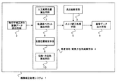
本発明の画像補正処理システム1のシステム構成の一例を図1のシステム構成図に示す。画像補正処理システム1は、幾何学補正済み画像データ読込手段2と衛星仰角・衛星方位角演算手段3と高さ演算手段4とオルソ補正処理手段5と画像データ出力手段6とを有する。尚、画像補正処理システム1は、コンピュータ端末上で実行され、各演算等は、当該コンピュータ端末のCPU等の処理演算部で実行される。
An example of the system configuration of the image
幾何学補正済み画像データ読込手段2は、人工衛星で撮像した衛星画像データに対して、システム補正処理や精密幾何補正処理を施した幾何学補正済み画像データを読み込み、記憶する手段である。尚、本明細書では、システム補正処理や精密幾何補正処理のいずれが施されていても良い。幾何学補正済み画像データ読込手段2は、幾何学補正済み画像データに付属している又は公開されている所定のパラメータも読み込み、記憶する。このパラメータとしては、人工衛星自体及びセンサの性能・移動について公開されている情報(人工衛星公開情報:衛星高度、軌道傾斜角、公転周期、撮像時の走査速度等)と、人工衛星が撮像を行う際の情報(画像データ付属情報:1回の観測範囲の特定位置(地点Cとする)に付属する撮像時の衛星仰角、衛星方位角、走査方向、投影面の楕円体高等)がある。 The geometrically corrected image data reading means 2 is means for reading and storing geometrically corrected image data obtained by performing system correction processing and precise geometric correction processing on satellite image data captured by an artificial satellite. In this specification, either system correction processing or precise geometric correction processing may be performed. The geometrically corrected image data reading means 2 also reads and stores predetermined parameters attached to or disclosed in the geometrically corrected image data. The parameters include the public information on the satellite itself and the performance and movement of the sensor (satellite public information: satellite altitude, orbital tilt angle, revolution period, scanning speed at the time of imaging, etc.) There is information (image data attached information: satellite elevation angle at the time of imaging, satellite azimuth, scanning direction, ellipsoid height of the projection plane, etc.) attached to a specific position (referred to as point C) in one observation range.
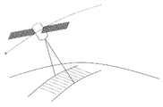
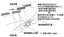
人工衛星が地表を撮像する際の概念図を図7に示す。 FIG. 7 shows a conceptual diagram when the artificial satellite images the ground surface.
衛星仰角・衛星方位角演算手段3は、幾何学補正済み画像データ読込手段2で読み込んだ人工衛星公開情報と画像データ付属情報とに基づいて、既知の地点C及びそのときの衛星位置を始点として、その前後の人工衛星の位置と走査位置とを推定することで、幾何学補正済み画像データ内の各地点に於ける、人工衛星の衛星仰角と衛星方位角とを演算する手段である。この概念を図8に示す。衛星仰角・衛星方位角演算手段3は、人工衛星位置算出手段7と軌道面ベクトル算出手段8と走査位置推定手段9と仰角・方位角算出手段10とからなる。 The satellite elevation angle / satellite azimuth calculation means 3 starts from a known point C and the satellite position at that time based on the public satellite information read by the geometrically corrected image data reading means 2 and the image data attached information. It is a means for calculating the satellite elevation angle and the satellite azimuth angle of the artificial satellite at each point in the geometrically corrected image data by estimating the position and scanning position of the artificial satellite before and after that. This concept is shown in FIG. The satellite elevation angle / satellite azimuth calculation means 3 includes an artificial satellite position calculation means 7, an orbital plane vector calculation means 8, a scanning position estimation means 9, and an elevation angle / azimuth angle calculation means 10.
具体的には、人工衛星位置算出手段7で地点Cの位置を幾何学補正済み画像データで決定した後、地点Cに於ける衛星仰角と衛星方位角及び衛星高度から地点Cが観測された時の人工衛星の位置を演算する。そして軌道面ベクトル算出手段8が地点Cの観測前後の人工衛星の軌道を再構成する。そして、走査位置推定手段9で地点Cの観測前後の走査位置を、画像データ付属情報の走査方向と人工衛星公開情報の走査速度から推定する。そうすると、衛星位置と走査位置とが対応づけられるので、幾何学補正済み画像データ内の各地点を走査位置として示し、仰角・方位角算出手段10で各地点での衛星仰角と衛星方位角を演算することとなる。
Specifically, after the position of the point C is determined from the geometrically corrected image data by the artificial satellite position calculating means 7, the point C is observed from the satellite elevation angle, the satellite azimuth and the satellite altitude at the point C. Calculate the position of the artificial satellite. The orbital plane vector calculating means 8 reconstructs the orbit of the artificial satellite before and after the observation of the point C. Then, the scanning position estimation means 9 estimates the scanning position before and after the observation of the point C from the scanning direction of the image data attached information and the scanning speed of the satellite public information. Then, since the satellite position and the scanning position are associated with each other, each point in the geometrically corrected image data is indicated as the scanning position, and the elevation angle /
高さ演算手段4は、楕円体高データ(標高データ及びジオイド高データから作成する等してこの楕円体高データを予め用意しておき、それを読み込むことが好適であるが、それに限定するものではなく、高さ演算手段4で楕円体高データを、その元となるデータ(標高データ及びジオイド高データ)から作成しても良い)と、幾何学補正済み画像データの投影面の楕円体高から、幾何学補正済み画像データ内の各点に於ける投影面からの高さを演算する手段である。 It is preferable that the height calculation means 4 prepares ellipsoidal height data in advance by preparing ellipsoidal height data (for example, by creating from altitude data and geoid height data, but it is not limited thereto). The height calculation means 4 may create ellipsoidal height data from the original data (elevation data and geoid height data) and the ellipsoidal height on the projection plane of the geometrically corrected image data. It is means for calculating the height from the projection plane at each point in the corrected image data.
オルソ補正処理手段5は、衛星仰角・衛星方位角演算手段3で演算した人工衛星の衛星仰角と衛星方位角と、高さ演算手段4で演算した幾何学補正済み画像データ内の各点に於ける投影面からの高さとに基づいてオルソ補正処理を実行する手段である。 The ortho correction processing means 5 is used for the satellite elevation angle and satellite azimuth angle calculated by the satellite elevation angle / satellite azimuth calculation means 3 and at each point in the geometrically corrected image data calculated by the height calculation means 4. And means for executing an ortho correction process based on the height from the projection plane.
画像データ出力手段6は、幾何学補正済み画像データに対してオルソ補正処理を実行した処理後の画像データを、ディスプレイ等の表示装置、プリンタ等の印刷装置、のような各種の出力装置に出力する手段である。 The image data output means 6 outputs the processed image data obtained by executing the ortho correction process on the geometrically corrected image data to various output devices such as a display device such as a display and a printing device such as a printer. It is means to do.
次に本発明の画像補正処理システム1の処理プロセスの流れの一例を図2のフローチャート図と図1のシステム構成図とを用いて詳細に説明する。
Next, an example of the process flow of the image
まず、幾何学補正済み画像データ読込手段2は、人工衛星により撮像された衛星画像データに対して、システム補正処理、精密幾何補正処理等の補正処理が施された幾何学補正済み画像データを読み込み、記憶する(S100)。この幾何学補正済み画像データの読み込みの際には、幾何学補正済み画像データ読込手段2は、幾何学補正済み画像データに付属している又は公開されている所定のパラメータも読み込み、記憶する(S110)。 First, the geometrically corrected image data reading means 2 reads geometrically corrected image data obtained by performing a correction process such as a system correction process and a precise geometric correction process on satellite image data captured by an artificial satellite. (S100). When reading the geometrically corrected image data, the geometrically corrected image data reading means 2 also reads and stores predetermined parameters attached to or disclosed in the geometrically corrected image data ( S110).
この読み込んだ各パラメータに基づいて、地点C及びその時の衛星位置を始点として、その前後の人工衛星の位置と走査位置とを推定することで、衛星仰角・衛星方位角演算手段3は、システム幾何学補正済み画像データ内の各地点に於ける、人工衛星の衛星仰角と衛星方位角とを演算する(S120〜S150)。 Based on the read parameters, the satellite elevation angle / satellite azimuth calculating means 3 estimates the position of the artificial satellite before and after the point C and the satellite position at that time and the scanning position, and the satellite azimuth calculating means 3 The satellite elevation angle and satellite azimuth angle of each artificial satellite at each point in the corrected image data are calculated (S120 to S150).
まず、衛星仰角・衛星方位角演算手段3の人工衛星位置算出手段7は、幾何学補正済み画像データの地点Cの緯度、経度、楕円体高(φC,λC、hC)を決定する。地点Cの位置が幾何学補正済み画像データの付属情報として与えられていればその値を用い、与えられていない場合には、別の情報から算出して用いる。例えば、地点Cが観測範囲の中心点であり、その位置は与えられていないが観測範囲の四隅の位置が与えられている場合には、その四隅の位置から中心点の位置を算出して用いる。通常、これら幾何学補正済み画像データの付属情報として与えられているのは水平位置(緯度、経度、或いはそれに代わる地図座標)のみであるので、楕円体高は地点Cの緯度、経度から別途準備した楕円体高データ等を用いて算出することとなる。 First, the satellite position calculation means 7 of the satellite elevation angle / satellite azimuth calculation means 3 determines the latitude, longitude, and ellipsoidal height (φ C , λ C , h C ) of the point C of the geometrically corrected image data. If the position of the point C is given as ancillary information of the geometrically corrected image data, the value is used, and if not, it is calculated from another information and used. For example, when the point C is the center point of the observation range and the position is not given but the positions of the four corners of the observation range are given, the position of the center point is calculated from the positions of the four corners and used. . Normally, only the horizontal position (latitude, longitude, or alternative map coordinates) is given as ancillary information of these geometrically corrected image data, so the ellipsoidal height is prepared separately from the latitude and longitude of the point C. Calculation is performed using ellipsoidal height data or the like.
地点Cの座標をECR座標CECR(xC,yC,zC)に変換する。尚、ECR座標とは、地球固定座標系(Earth-Centered Rotation)であり、その原点を地球中心、z軸を北極方向、x軸を経度0°方向とする座標系である。 The coordinates of the point C are converted into ECR coordinates C ECR (x C , y C , z C ). The ECR coordinate is an earth-centered rotation system (Earth-Centered Rotation). The origin is the center of the earth, the z-axis is the north pole direction, and the x-axis is the 0 ° longitude direction.
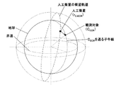
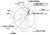
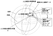
地点CのECR座標を決定した後、衛星仰角・衛星方位角演算手段3の人工衛星位置算出手段7は、それに基づいて地点Cが観測された時の人工衛星の衛星位置rを演算する。図9に示すように、人工衛星はその衛星軌道上のある点rC−ECRから、地表の観測対象地点CECRを撮像している。 After determining the ECR coordinates of the point C, the satellite position calculating means 7 of the satellite elevation angle / satellite azimuth calculating means 3 calculates the satellite position r of the artificial satellite when the point C is observed based on it. As shown in FIG. 9, the artificial satellite images the observation target point C ECR on the ground surface from a point r C-ECR on the satellite orbit.
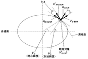
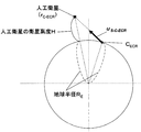
図10は、図9の地点CECRを通る子午線(経線)の断面を示した図である。尚、下記の説明の地心緯度と測地緯度の違いが分かりやすいように、縦横比は強調してある。尚、地心緯度とは、地球中心から地点CECRに対する緯度であり、測地緯度とは、地点CECRの地表に対する垂線と赤道面とからなる緯度である。 FIG. 10 is a diagram showing a cross section of a meridian (meridian) passing through the point CECR in FIG. In addition, the aspect ratio is emphasized so that the difference between the geocentric latitude and the geodetic latitude described below can be easily understood. Note that the geocentric latitude, a latitude with respect to the point C ECR from the earth center, the geodetic latitude, the latitude comprising a perpendicular line and the equatorial plane to the ground point C ECR.
まず、地点CECRの単位ベクトルuC−ECRを算出する。ベクトルは、図中では判別しやすいように太斜字で示す。そして、地点CECRに於ける地心緯度ψCを算出し、その地点に於ける単位ベクトルuC−ECRに直交する北向きベクトルuN−C−ECRを算出し、更にそれを地心緯度ψCと測地緯度φCの差φだけ回転することで測地面上の北向きベクトルu’N−C−ECRを算出し、更に測地面に垂直なベクトルu’C−ECRを算出する。 First calculates the unit vector u C-ECR point C ECR. The vector is shown in bold italics for easy identification in the figure. Then, the geocentric latitude ψ C at the point C ECR is calculated, the north-facing vector u N-C-ECR orthogonal to the unit vector u C-ECR at the point is calculated, and further, the geocentric latitude is calculated. [psi C and 'calculates the N-C-ECR, perpendicular vector u further geodetic surface' north vector u on the ground measurement by rotating only difference phi geodetic latitude phi C calculates the C-ECR.
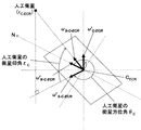
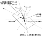
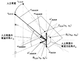
図11に地点CECR周辺の測地面と、地点CECRが観測された時の人工衛星の衛星位置を俯瞰した場合の概念図を示す。測地面上の北向きベクトルu’N−C−ECRを、前記読み込んだ地点Cの画像データ付属情報の衛星方位角θCに基づいて、地点Cに於ける衛星方位角θCだけ回転させ、地点CECRに於ける測地面上の衛星方向のベクトルu’S−C−ECRを算出する。そして、前記読み込んだ地点Cでの画像データ付属情報の衛星仰角εCを用いて、地点CECRに於ける人工衛星の方向ベクトルuS−C−ECRを算出する。 FIG. 11 shows a conceptual diagram in a case where an overhead view of the ground measurement around the point C ECR and the satellite position of the artificial satellite when the point C ECR is observed. The north-facing vector u ′ N-C-ECR on the geodesic plane is rotated by the satellite azimuth angle θ C at the point C based on the satellite azimuth angle θ C of the image data attached information of the read point C, A vector u ′ S-C-ECR in the direction of the satellite on the ground surface at the point C ECR is calculated. Then, using satellite elevation epsilon C of the image data attached information in the read point C, and calculates the direction vector u S-C-ECR of in satellites to the point C ECR.
図12は、地点CECRと人工衛星とを含み、且つ地球の中心を通る断面を示した図である。地点CECRに於ける人工衛星の方向ベクトルuS−C−ECR、地球半径RE、幾何学補正済み画像データ読込手段2で読み込んだ人工衛星公開情報に於ける衛星高度Hから、地点Cが観測された時の人工衛星の位置ベクトルrC−ECRを算出する。 FIG. 12 is a diagram showing a cross section including the point C ECR and the artificial satellite and passing through the center of the earth. From the satellite direction vector u S-C-ECR at the point C ECR , the earth radius R E , and the satellite altitude H in the satellite public information read by the geometrically corrected image data reading means 2, the point C is The position vector r C-ECR of the artificial satellite when observed is calculated.
以上のような処理を実行することで、人工衛星位置算出手段7は、地点Cが観測された時の人工衛星の位置を演算できる(S120)。 By executing the processing as described above, the artificial satellite position calculating means 7 can calculate the position of the artificial satellite when the point C is observed (S120).
次に、衛星仰角・衛星方位角演算手段3の軌道面ベクトル算出手段8は、人工衛星の位置から、地点Cの観測前後の人工衛星の軌道を再構成する(即ち人工衛星軌道の軌道面ベクトルを算出する)(S130)。 Next, the orbital plane vector calculating means 8 of the satellite elevation angle / satellite azimuth calculating means 3 reconstructs the orbit of the artificial satellite before and after the observation of the point C from the position of the artificial satellite (that is, the orbital plane vector of the artificial satellite orbit). (S130).
図13に地球周囲の衛星軌道上を移動する人工衛星の動きを示す。S120で算出した人工衛星の位置ベクトルrC−ECRに於ける地心緯度ψrCを算出する。そして幾何学補正済み画像データ読込手段2で読み込んだ人工衛星公開情報に於ける軌道傾斜角に基づいて、ECI座標系(ECI座標系とは、Earth-Centered Inertial:地球慣性座標系。その原点を地球中心、z軸を北極方向、x軸を春分点方向とする座標系)に於ける人工衛星の速度ベクトルと子午線(経線)のなす角I’ECI−ψ−rCを算出する。 FIG. 13 shows the movement of an artificial satellite moving on the satellite orbit around the earth. The geocentric latitude ψ rC in the position vector r C-ECR of the artificial satellite calculated in S120 is calculated. Then, based on the orbital inclination angle in the satellite public information read by the geometrically corrected image data reading means 2, the ECI coordinate system (ECI coordinate system is Earth-Centered Inertial: Earth inertia coordinate system. An angle I ′ ECI−ψ−rC formed by the velocity vector of the satellite and the meridian (meridian) at the center of the earth, the z-axis as the north pole direction, and the x-axis as the equinox direction is calculated.
又、人工衛星の公転周期から人工衛星の角速度ωS−ECIを算出し、ECI座標系に於ける人工衛星の速度VECIを算出する。そして、人工衛星の衛星位置rC−ECRに於いてECR座標系に於ける人工衛星の速度VECR、人工衛星の公転角速度ωS−ECR、人工衛星の速度ベクトルと子午線(経線)のなす角I’ECR−ψ−rCを算出し、人工衛星の単位ベクトルur−C−ECRを算出する。 Further, the angular velocity ω S-ECI of the artificial satellite is calculated from the revolution period of the artificial satellite, and the velocity V ECI of the artificial satellite in the ECI coordinate system is calculated. Then, at the satellite position r C-ECR of the satellite, the velocity V ECR of the satellite in the ECR coordinate system, the revolution angular velocity ω S-ECR of the satellite, the angle formed between the velocity vector of the satellite and the meridian (meridian). I ′ ECR-ψ-rC is calculated, and the unit vector u r-C-ECR of the artificial satellite is calculated.
図14は、人工衛星の方向ベクトルuS−E−C−ECRに直交する面を示した図である。人工衛星の方向ベクトルuS−E−C−ECRに直交する北向きの単位ベクトルuNro−C−ECRを算出し、それを角度I’ECRーψーrCだけ回転したベクトルu’Nro−C−ECRを算出し、軌道面ベクトルuo−C−ECRを算出する。 FIG. 14 is a diagram illustrating a plane orthogonal to the direction vector u S-E-C-ECR of the artificial satellite. A unit vector u Nro-C-ECR facing north that is orthogonal to the direction vector u S-E-C-ECR of the satellite is calculated, and the vector u ′ Nro-C rotated by an angle I ′ ECR−ψ−rC -ECR is calculated, and the orbital plane vector uo -C-ECR is calculated.
このような処理を実行することで、軌道面ベクトル算出手段8は、地点Cの観測前後の人工衛星の軌道を再構成することが出来る。 By executing such processing, the orbital plane vector calculating means 8 can reconstruct the orbit of the artificial satellite before and after the observation of the point C.
地点Cの観測前後の人工衛星の軌道の再構成後、走査位置推定手段9が、地点Cの観測前後の走査位置を、与えられた走査方向と走査速度とから推定する(S140)。 After reconstruction of the orbit of the artificial satellite before and after the observation at the point C, the scanning position estimation means 9 estimates the scanning position before and after the observation at the point C from the given scanning direction and scanning speed (S140).
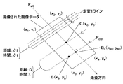
図15は、幾何学補正済み画像データ上で、地点Cと、その幾何学補正済み画像データ内の任意の点Bとの位置関係を示した図である。地点Cを通り、走査方向に平行な直線FalCを表す式を算出し、幾何学補正済み画像データ内の任意の点Bを通り走査方向に直交する直線FcrBを表す式を算出し、それらの交点B0の座標を算出する。 FIG. 15 is a diagram showing a positional relationship between a point C and an arbitrary point B in the geometrically corrected image data on the geometrically corrected image data. Through the point C, calculates an expression representing a straight line parallel to F alC in the scanning direction, and calculates an equation expressing a straight line F CRB perpendicular any point B geometric in the corrected image data as the scan direction, they calculating the intersections B 0 coordinates.
そして地点Cと地点B0の距離Dを算出し、距離Dと、走査方向に平行な観測時の地上解像度δl、及び走査速度(1ラインの走査にかかる時間)δtから、地点Cが観測されてから地点Bが観測されるまでの時間差tを算出する。つまり、地点Bが観測された時刻を地点Cが観測された時刻からの相対時刻で表す。 Then, the distance D between the point C and the point B 0 is calculated. From the distance D, the ground resolution δ l at the time of observation parallel to the scanning direction, and the scanning speed (time required for scanning one line) δ t , the point C is The time difference t from the observation until the point B is observed is calculated. That is, the time when the point B is observed is expressed as a relative time from the time when the point C is observed.
このような処理を実行することで、地点Bの位置は、地点Cが観測された時刻からの相対時刻として表されることとなる。 By executing such processing, the position of the point B is expressed as a relative time from the time when the point C was observed.
S130及びS140で算出した人工衛星の位置と走査位置が、共に地点Cが観測された時刻からの相対時刻の関数としてあらわされることから、人工衛星の衛星位置と走査位置とが対応づけられる。そこで、次に、衛星仰角・衛星方位角演算手段3の仰角・方位角算出手段10は、幾何学補正済み画像データ内の各地点を走査位置として表し、その位置での衛星仰角と衛星方位角とを算出する(S150)。 Since the position of the artificial satellite calculated in S130 and S140 and the scanning position are both expressed as a function of the relative time from the time when the point C is observed, the satellite position of the artificial satellite and the scanning position are associated with each other. Therefore, next, the elevation angle / azimuth calculation means 10 of the satellite elevation angle / satellite azimuth calculation means 3 represents each point in the geometrically corrected image data as a scanning position, and the satellite elevation angle and satellite azimuth at that position. Are calculated (S150).
まず、S140で算出した時間差tから、地点C及び地点Bが観測された時の人工衛星の衛星位置間の角度ωを算出し、地点Bが観測された時の衛星位置rB−ECRを算出する。この概念図を図16に示す。 First, from the time difference t calculated in S140, the angle ω between the satellite positions of the artificial satellites when the point C and the point B are observed is calculated, and the satellite position r B-ECR when the point B is observed is calculated. To do. This conceptual diagram is shown in FIG.
そして、地点Bの緯度、経度、楕円体高(B(φB,λB,hB))を算出し、それをECR座標系に変換する。この変換後の座標が、BECR(xB,yB,zB)であるとする。 Then, the latitude, longitude, and ellipsoidal height (B (φ B , λ B , h B )) of the point B are calculated and converted to the ECR coordinate system. It is assumed that the coordinates after this conversion are B ECR (x B , y B , z B ).
図17は、地点BECR及び地点CECR周辺の測地面と、地点BECR及びCECRが観測された時の人工衛星の衛星位置を示した図である。ここで、地点BECRに於ける地心(地球の中心)方向の単位ベクトルuBーECRを算出し、地点BECRに於ける測地面に垂直なベクトルu’B−ECRを算出し、地点BECRに於ける北向きベクトルuN−B−ECRを算出する。そして、地点BECRから人工衛星への視線ベクトルrS−B−ECR及びその単位ベクトルuS−B−ECRを算出する。これによって、地点BECRに於ける衛星仰角εBを算出でき、又、地点BECRに於ける測地面上の人工衛星の衛星方向のベクトルu’S−B−ECRを算出し、地点BECRに於ける衛星方位角θBを算出できる。 FIG. 17 is a diagram showing the ground surface around the point B ECR and the point C ECR and the satellite positions of the artificial satellites when the points B ECR and CECR are observed. Here, to calculate a unit vector u B over the ECR in geocentric to point B ECR (the center of the Earth) directions, calculates a vector perpendicular u 'B-ECR to ground measurement in the point B ECR, point calculating the in north vector u N-B-ECR to B ECR. Then, the line-of-sight vector r S-B- ECR from the point B ECR to the artificial satellite and its unit vector u S-B-ECR are calculated. This allows calculating the in satellite elevation angle epsilon B to the point B ECR, also calculates a vector u 'S-B-ECR satellite direction satellite on the ground measurement in the point B ECR, point B ECR The satellite azimuth angle θ B at can be calculated.
このようにして衛星仰角・衛星方位角演算手段3の仰角・方位角算出手段10は、幾何学補正済み画像データ内の任意の地点Bでの衛星仰角と衛星方位角とを算出できる。 In this way, the elevation angle / azimuth angle calculation means 10 of the satellite elevation angle / satellite azimuth angle calculation means 3 can calculate the satellite elevation angle and the satellite azimuth angle at an arbitrary point B in the geometrically corrected image data.
次に、高さ演算手段4は、標高データ及びジオイド高データから予め作成した楕円体高データと、幾何学補正済み画像データ読込手段2で読み込んだ幾何学補正済み画像データの投影面の楕円体高とから、幾何学補正済み画像データ内の各地点に於ける投影面からの高さを演算する(S160)。 Next, the height calculation means 4 includes ellipsoidal height data created in advance from the elevation data and geoid height data, and the ellipsoidal height of the projection plane of the geometrically corrected image data read by the geometrically corrected image data reading means 2. Then, the height from the projection plane at each point in the geometrically corrected image data is calculated (S160).
S150及びS160で算出した、衛星仰角、衛星方位角、高さとのデータに基づいて、オルソ補正処理手段5は、幾何学補正済み画像データに対してオルソ補正処理を行う(S170)。 Based on the satellite elevation angle, satellite azimuth angle, and height data calculated in S150 and S160, the ortho correction processing means 5 performs ortho correction processing on the geometrically corrected image data (S170).
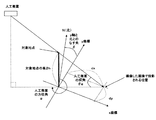
オルソ補正処理は、ある観測対象地点Bの高度に起因する位置のずれの量と方向を演算することになるので、下記の数1により算出する。この概念図を図18に示す。
尚、数1に於いて、dxは画像座標系上でのx軸方向の位置のずれであり、dyは画像座標系上でのy軸方向の位置のずれであり、hは対象地点の投影面からの高さであり、θeは人工衛星の衛星仰角であり、αは人工衛星の衛星方位角であり、βは画像座標系のy軸と北(真北)とのなす角(幾何学補正済み画像データの補正処理結果のパラメータとして与えられている)である。
In
そうすると、対象地点Bでの人工衛星の衛星仰角θeはS150で算出したεBであり、人工衛星の衛星方位角αはS150で算出したθBであり、又、対象地点の高度hはS160で算出した高さである。そうすると、全ての変数が判明しているので、これらの値を上述の数1に代入して演算すれば、dx、dyが算出できる。従って、このdx、dyの値に基づいて、オルソ補正処理手段5は、対象地点Bをdx、dyだけ位置をずらす補正処理を行う。
Then, the satellite elevation angle θ e of the artificial satellite at the target point B is ε B calculated in S150, the satellite azimuth angle α of the artificial satellite is θ B calculated in S150, and the altitude h of the target point is S160. This is the height calculated in. Then, since all the variables are known, dx and dy can be calculated by substituting these values into the
このようにして幾何学補正済み画像データに対してオルソ補正処理を実行した処理後の画像データを、画像データ出力手段6が、ディスプレイ等の表示装置、プリンタ等の印刷装置、のような各種の出力装置に出力する(S180)。 In this way, the image data output means 6 outputs the processed image data obtained by executing the ortho correction process on the geometrically corrected image data, such as a display device such as a display and a printing device such as a printer. Output to the output device (S180).
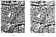
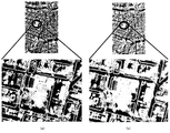
図19(a)にオルソ補正処理前の画像データ(即ち幾何学補正済み画像データ)、図19(b)にオルソ補正処理後の画像データを示す。尚、位置補正処理が行われていることをわかりやすくする為に、各画像データには街区を示す地図を重ね合わせている。図19(a)、図19(b)の拡大図を図20(a)、図20(b)に示す。 FIG. 19A shows image data before ortho correction processing (that is, image data after geometric correction), and FIG. 19B shows image data after ortho correction processing. In addition, in order to make it easy to understand that the position correction process is being performed, a map indicating a block is superimposed on each image data. FIGS. 20A and 20B are enlarged views of FIGS. 19A and 19B.
図20を比較して分かるように、街区の位置が補正されていることが把握できる。 As can be seen by comparing FIG. 20, it can be understood that the position of the block is corrected.
尚、上述した画像補正処理システム1の処理の内容を記録した画像補正処理プログラムがCD−ROMやDVD等の記録媒体に記録され、それがコンピュータ端末に読み込まれることによって、画像補正処理システム1を実現しても良い。又、当該画像補正処理プログラムが所定のサーバからネットワークを介してコンピュータ端末にダウンロードされることでコンピュータ端末に読み込まれ、画像補正処理システム1を実現しても良い。
The image correction processing program in which the contents of the processing of the above-described image
この場合、画像補正処理プログラムは、幾何学補正済み画像データ読込手段2をコンピュータ端末で実行する機能(モジュールやプログラム。以下同様)と、衛星仰角・衛星方位角演算手段3をコンピュータ端末で実行する機能と、高さ演算手段4をコンピュータ端末で実行する機能と、オルソ補正処理手段5をコンピュータ端末で実行する機能と、画像データ出力手段6をコンピュータ端末で実行する機能とを有している。 In this case, the image correction processing program executes the function (module or program; the same applies hereinafter) for executing the geometrically corrected image data reading means 2 on the computer terminal and the satellite elevation angle / satellite azimuth calculating means 3 on the computer terminal. A function for executing the height calculation means 4 on the computer terminal, a function for executing the ortho correction processing means 5 on the computer terminal, and a function for executing the image data output means 6 on the computer terminal.
この画像補正処理プログラムを記録した記録媒体がコンピュータ端末にセットされ、それがコンピュータ端末に読み込まれることによって、上述の各機能がコンピュータ端末の処理演算部(CPUやレジスタ等の演算装置)や記憶部(メモリやキャッシュ、ハードディスク等)に読み込まれる。 A recording medium on which the image correction processing program is recorded is set in a computer terminal, and when the recording medium is read into the computer terminal, the above-described functions are processed by a processing operation unit (an arithmetic device such as a CPU or a register) or a storage unit of the computer terminal. (Memory, cache, hard disk, etc.)
幾何学補正済み画像データ読込手段2は、幾何学補正済み画像データと上述の各パラメータを読み込み、記憶部に記憶する。そして処理演算部に読み込まれた衛星仰角・衛星方位角演算手段3は、前記記憶部に記憶した各パラメータに基づいて、上述と同様に人工衛星の衛星仰角、衛星方位角を演算し、記憶部に記憶する。又、処理演算部に読み込まれた高さ演算手段4は、前記記憶部に記憶した各パラメータに基づいて、上述と同様に幾何学補正済み画像データ内の各地点に於ける投影面からの高さを演算する。記憶部に記憶した人工衛星の衛星仰角、衛星方位角と、幾何学補正済み画像データ内の各地点に於ける投影面からの高さと、幾何学補正済み画像データとに基づいて、処理演算部に読み込まれたオルソ補正処理手段5は、幾何学補正済み画像データに対して上述と同様にオルソ補正処理を行う。そしてその処理後の画像データを、処理演算部に読み込まれた画像データ出力手段6が、表示装置や印刷装置等の出力装置から出力する。 The geometrically corrected image data reading means 2 reads the geometrically corrected image data and the above-described parameters and stores them in the storage unit. Then, the satellite elevation angle / satellite azimuth angle calculation means 3 read by the processing calculation unit calculates the satellite elevation angle and satellite azimuth angle of the artificial satellite based on the parameters stored in the storage unit in the same manner as described above. To remember. Further, the height calculation means 4 read by the processing calculation unit is based on the parameters stored in the storage unit, and the height from the projection plane at each point in the geometrically corrected image data as described above. Calculate the length. Based on the satellite elevation angle and satellite azimuth, the height from the projection plane at each point in the geometrically corrected image data, and the geometrically corrected image data stored in the storage unit The ortho correction processing means 5 read in (5) performs ortho correction processing on the geometrically corrected image data in the same manner as described above. Then, the image data output means 6 read by the processing operation unit outputs the processed image data from an output device such as a display device or a printing device.
画像補正処理プログラムがネットワークからコンピュータ端末にダウンロードされた場合も、画像補正処理プログラムが記録された記録媒体をコンピュータ端末で実行する場合と同様である。 The case where the image correction processing program is downloaded from the network to the computer terminal is the same as the case where the recording medium on which the image correction processing program is recorded is executed on the computer terminal.
本発明に於ける各手段は、その機能が論理的に区別されているのみであって、物理上あるいは事実上は同一の領域を為していても良い。 Each means in the present invention is only logically distinguished in function, and may be physically or practically the same area.
尚、本発明を実施するにあたり本実施態様の機能を実現するソフトウェアのプログラムを記録した記憶媒体をシステムに供給し、そのシステムのコンピュータが記憶媒体に格納されたプログラムを読み出し実行することによって実現されることは当然である。 In implementing the present invention, a storage medium storing a software program for realizing the functions of this embodiment is supplied to the system, and the computer of the system reads and executes the program stored in the storage medium. Of course.
この場合、記憶媒体から読み出されたプログラム自体が前記した実施態様の機能を実現することとなり、そのプログラムを記憶した記憶媒体は本発明を当然のことながら構成することになる。 In this case, the program itself read from the storage medium realizes the functions of the above-described embodiments, and the storage medium storing the program naturally constitutes the present invention.
プログラムを供給する為の記憶媒体としては、例えば磁気ディスク、ハードディスク、光ディスク、光磁気ディスク、磁気テープ、不揮発性のメモリカード等を使用することができる。 As a storage medium for supplying the program, for example, a magnetic disk, a hard disk, an optical disk, a magneto-optical disk, a magnetic tape, a nonvolatile memory card, or the like can be used.
又、コンピュータが読み出したプログラムを実行することにより、上述した実施態様の機能が実現されるだけではなく、そのプログラムの指示に基づき、コンピュータ上で稼働しているオペレーティングシステムなどが実際の処理の一部又は全部を行い、その処理によって前記した実施態様の機能が実現される場合も含まれることは言うまでもない。 Further, by executing the program read by the computer, not only the functions of the above-described embodiments are realized, but also an operating system running on the computer is one of the actual processes based on the instructions of the program. It goes without saying that the case where the function of the above-described embodiment is realized by performing part or all of the processing and the processing thereof is also included.
更に、記憶媒体から読み出されたプログラムが、コンピュータに挿入された機能拡張ボードやコンピュータに接続された機能拡張ユニットに備わる不揮発性あるいは揮発性の記憶手段に書き込まれた後、そのプログラムの指示に基づき、機能拡張ボードあるいは機能拡張ユニットに備わる演算処理装置などが実際の処理の一部あるいは全部を行い、その処理により前記した実施態様の機能が実現される場合も含まれることは当然である。
Furthermore, after the program read from the storage medium is written in the nonvolatile or volatile storage means provided in the function expansion board inserted into the computer or the function expansion unit connected to the computer, the program is instructed. On the basis of the above, it is natural that the arithmetic processing device or the like provided in the function expansion board or the function expansion unit performs part or all of the actual processing and the functions of the above-described embodiments are realized by the processing.
本発明を用いることによって、幾何学補正済み画像データに対してそれに付属している情報又は公開されている情報から画像内の各地点から見た人工衛星の衛星仰角及び衛星方位角を算出することで、従来より精度の高い、幾何学補正済み画像データに対するオルソ補正処理を行う画像補正処理システムが可能となる。
By using the present invention, the satellite elevation angle and the satellite azimuth angle of the artificial satellite viewed from each point in the image are calculated from the information attached to the geometrically corrected image data or the published information. Thus, an image correction processing system that performs ortho correction processing on geometrically corrected image data with higher accuracy than before can be realized.
1:画像補正処理システム
2:幾何学補正済み画像データ読込手段
3:衛星仰角・衛星方位角演算手段
4:高さ演算手段
5:オルソ補正処理手段
6:画像データ出力手段
7:人工衛星位置算出手段
8:軌道面ベクトル算出手段
9:走査位置推定手段
10:仰角・方位角算出手段
1: Image correction processing system 2: Geometrically corrected image data reading means 3: Satellite elevation angle / satellite azimuth calculation means 4: Height calculation means 5: Ortho correction processing means 6: Image data output means 7: Satellite position calculation Means 8: Orbital plane vector calculating means 9: Scanning position estimating means 10: Elevation angle / azimuth angle calculating means
Claims (9)
前記幾何学補正済み画像データを読み込む幾何学補正済み画像データ読込手段と、
前記人工衛星の性能・移動に関する人工衛星公開情報と、前記人工衛星が撮像した場合の情報である画像データ付属情報とに基づいて、前記幾何学補正済み画像データ内の任意の地点に於ける人工衛星の衛星仰角、衛星方位角を算出する衛星仰角・衛星方位角演算手段と、
前記任意の地点の楕円体高データと前記幾何学補正済み画像データの投影面の楕円体高とから、前記幾何学補正済み画像データ内の前記任意の地点の投影面からの高さを演算する高さ演算手段と、
前記任意の地点に於ける衛星仰角、衛星方位角、投影面からの高さに基づいてオルソ補正処理を実行し、前記幾何学補正済み画像データの高さに起因する歪みを補正するオルソ補正処理手段と、
を有することを特徴とする画像補正処理システム。 An image correction processing system that performs ortho correction processing on geometrically corrected image data obtained by performing geometric correction processing on image data captured by an artificial satellite,
A geometrically corrected image data reading means for reading the geometrically corrected image data;
Based on the public satellite information relating to the performance and movement of the artificial satellite and the image data attached information that is information when the artificial satellite takes an image, the artificial satellite at any point in the geometrically corrected image data Satellite elevation angle / satellite azimuth calculation means for calculating the satellite elevation angle and satellite azimuth angle of the satellite,
The height for calculating the height from the projection surface of the arbitrary point in the geometrically corrected image data from the ellipsoidal height data of the arbitrary point and the ellipsoidal height of the projection surface of the geometrically corrected image data Computing means;
Orthorectification processing that executes orthorectification processing based on the satellite elevation angle, satellite azimuth angle, and height from the projection plane at the arbitrary point to correct distortion caused by the height of the geometrically corrected image data. Means,
An image correction processing system comprising:
前記画像データ付属情報に於ける既知の地点の衛星仰角と衛星方位角と、前記人工衛星公開情報に於ける衛星高度と、地球の半径とを用いて前記既知の地点が観測された時の人工衛星の位置を算出する人工衛星位置算出手段と、
前記算出した人工衛星の位置と、前記人工衛星公開情報に於ける人工衛星の軌道傾斜角と公転周期とを用いて前記人工衛星の軌道面ベクトルを算出する軌道面ベクトル算出手段と、
前記幾何学補正済み画像データ内の任意の地点と既知の地点との位置関係と、前記画像データ付属情報に於けるセンサの解像度と前記人工衛星公開情報に於ける走査速度とにより、前記任意の地点が観測された時刻を、前記既知の地点が観測された時刻からの相対時刻で算出する走査位置推定手段と、
前記軌道面ベクトルと、前記任意の地点が観測された相対時刻から、前記任意の地点が観測された時の人工衛星の位置を算出することで、前記任意の地点に於ける衛星仰角と衛星方位角とを算出する仰角・方位角算出手段と、
からなることを特徴とする請求項1に記載の画像補正処理システム。 The satellite elevation angle / satellite azimuth calculating means is:
When the known point is observed using the satellite elevation angle and satellite azimuth of the known point in the image data attached information, the satellite altitude in the artificial satellite public information, and the radius of the earth. Artificial satellite position calculating means for calculating the position of the satellite;
An orbital plane vector calculating means for calculating the orbital plane vector of the artificial satellite using the calculated position of the artificial satellite and the orbital inclination angle and revolution period of the artificial satellite in the artificial satellite public information;
According to the positional relationship between an arbitrary point in the geometrically corrected image data and a known point, the resolution of the sensor in the image data ancillary information, and the scanning speed in the artificial satellite public information, the arbitrary point Scanning position estimating means for calculating the time at which the point was observed as a relative time from the time at which the known point was observed;
By calculating the position of the artificial satellite when the arbitrary point is observed from the orbital plane vector and the relative time when the arbitrary point is observed, the satellite elevation angle and the satellite azimuth at the arbitrary point are calculated. An elevation angle / azimuth angle calculating means for calculating an angle;
The image correction processing system according to claim 1, comprising:
前記既知の地点の緯度・経度からその地点のECR座標系の座標を算出し、
前記既知の地点の単位ベクトルと地心緯度とを算出し、
前記単位ベクトルを用いて直交する北向きベクトルを算出し、
前記北向きベクトルを前記地心緯度と測地緯度の差だけ回転することで前記既知の地点の測地面上の北向きベクトルを算出し、
前記測地面上の北向きベクトルにより、前記測地面に垂直な垂直ベクトルを算出し、
前記読み込んだ画像データ付属情報に於ける前記既知の地点の衛星方位角だけ前記北向きベクトルを回転させることで、前記既知の地点の測地面上の衛星方向のベクトルを算出し、
前記読み込んだ既知の地点の衛星仰角を用いて、前記既知の地点に於ける人工衛星の方向ベクトルを算出し、
前記人工衛星の方向ベクトルと地球半径と前記人工衛星公開情報に於ける衛星高度とから、前記既知の地点が観測された時の人工衛星の位置ベクトルを算出する、ことで前記既知の地点が観測された時の人工衛星の位置を算出する、
ことを特徴とする請求項2に記載の画像補正処理システム。 The satellite position calculating means includes
Calculate the coordinates of the ECR coordinate system of the point from the latitude and longitude of the known point,
Calculating the unit vector and geocentric latitude of the known point;
Calculate an orthogonal north vector using the unit vector,
Rotating the north-facing vector by the difference between the geocentric latitude and the geodetic latitude to calculate a north-facing vector on the geodesic of the known point,
From the north-facing vector on the ground surface, a vertical vector perpendicular to the ground surface is calculated,
By rotating the north direction vector by the satellite azimuth of the known point in the read image data ancillary information, a satellite direction vector on the ground surface of the known point is calculated,
Using the satellite elevation angle of the read known point, calculate the direction vector of the artificial satellite at the known point,
The known point is observed by calculating the position vector of the artificial satellite when the known point is observed from the direction vector of the artificial satellite, the earth radius and the satellite altitude in the artificial satellite public information. Calculate the position of the satellite when
The image correction processing system according to claim 2.
前記人工衛星の位置ベクトルに於ける地心緯度を算出し、
前記人工衛星公開情報に於ける軌道傾斜角に基づいて、ECI座標系に於ける前記人工衛星の速度ベクトルと子午線のなす角を算出し、
前記人工衛星公開情報に於ける公転周期から公転角速度を算出することで、前記ECI座標系に於ける前記人工衛星の速度を算出し、
前記ECI座標系の速度、公転角速度、速度ベクトルと子午線のなす角を、ECR座標系に変換することで、前記人工衛星の単位ベクトルを算出し、
前記人工衛星の方向ベクトルに直交する北向きの単位ベクトルを算出し、それを前記ECR座標系の速度ベクトルと子午線のなす角だけ回転したベクトルを算出することにより、前記軌道面ベクトルを算出する、
ことを特徴とする請求項2又は請求項3に記載の画像補正処理システム。 The track surface vector calculating means includes:
Calculate the geocentric latitude in the position vector of the artificial satellite,
Based on the orbital inclination angle in the satellite public information, calculate the angle formed between the velocity vector of the satellite and the meridian in the ECI coordinate system,
By calculating the revolution angular velocity from the revolution period in the artificial satellite public information, the velocity of the artificial satellite in the ECI coordinate system is calculated,
The unit vector of the artificial satellite is calculated by converting the velocity of the ECI coordinate system, the revolution angular velocity, the angle formed by the velocity vector and the meridian into the ECR coordinate system,
Calculating a northward unit vector orthogonal to the direction vector of the artificial satellite, and calculating the vector obtained by rotating the unit vector by an angle formed by a velocity vector of the ECR coordinate system and a meridian;
The image correction processing system according to claim 2 or claim 3, wherein
前記幾何学補正済み画像データに於いて、前記既知の地点を通り走査方向に平行な直線と、前記任意の地点を通り走査方向に直交する直線との交点の座標を算出し、
前記既知の地点と前記交点との距離を算出し、
前記人工衛星のセンサの解像度と走査速度と、前記算出した距離とに基づいて、前記既知の地点が観測されてから前記任意の地点が観測されるまでの時間差を算出することで、前記任意の地点が観測された時刻を相対時刻で算出する、
ことを特徴とする請求項2に記載の画像補正処理システム。 The scanning position estimation means includes
In the geometrically corrected image data, calculate the coordinates of the intersection of a straight line passing through the known point and parallel to the scanning direction and a straight line passing through the arbitrary point and orthogonal to the scanning direction,
Calculating the distance between the known point and the intersection;
Based on the resolution and scanning speed of the sensor of the artificial satellite and the calculated distance, the time difference from the observation of the known point to the observation of the arbitrary point is calculated. Calculate the time at which the point was observed as a relative time,
The image correction processing system according to claim 2.
前記時間差から、前記既知の地点及び任意の地点が観測された時の人工衛星の衛星位置間の角度を算出することで、前記任意の地点が観測された時の人工衛星の位置を算出し、
前記任意の地点の座標をECR座標系で算出し、
前記ECR座標系に基づいて前記任意の地点の地心方向の単位ベクトルとその測地面に垂直な垂直ベクトルとを算出することで、前記任意の地点に於ける北向きベクトルを算出し、
前記任意の地点に於ける北向きベクトルから人工衛星への視線ベクトル及びその単位ベクトルとを算出することで、前記任意の地点に於ける衛星仰角を算出し、
前記任意の地点に於ける北向きベクトルからその測地面上の人工衛星の衛星方向のベクトルを算出することで、前記任意の地点に於ける衛星方位角を算出する、
ことを特徴とする請求項2から請求項5のいずれかに記載の画像補正処理システム。 The elevation angle / azimuth angle calculating means includes:
From the time difference, calculating the angle between the satellite position of the artificial satellite when the known point and the arbitrary point are observed, to calculate the position of the artificial satellite when the arbitrary point is observed,
Calculate the coordinates of the arbitrary point in the ECR coordinate system,
By calculating a unit vector in the geocentric direction of the arbitrary point based on the ECR coordinate system and a vertical vector perpendicular to the ground surface, a north direction vector at the arbitrary point is calculated,
By calculating the line-of-sight vector from the north-facing vector at the arbitrary point to the artificial satellite and its unit vector, the satellite elevation angle at the arbitrary point is calculated,
A satellite azimuth at the arbitrary point is calculated by calculating a satellite direction vector of the artificial satellite on the ground surface from the north-facing vector at the arbitrary point.
The image correction processing system according to any one of claims 2 to 5, wherein
前記幾何学補正済み画像データに対してオルソ補正処理を行った画像データを出力する画像データ出力手段を有する、
ことを特徴とする請求項1に記載の画像補正処理システム。 The image processing system further includes:
Image data output means for outputting image data obtained by performing ortho correction processing on the geometrically corrected image data;
The image correction processing system according to claim 1.
前記幾何学補正済み画像データ読込機能は、
人工衛星で撮像した画像データに対して幾何学補正処理を施した幾何学補正済み画像データを読み込み、前記記憶部に記憶し、
前記衛星仰角・衛星方位角演算機能は、
前記人工衛星の性能・移動に関する人工衛星公開情報と、前記人工衛星が撮像した場合の情報である画像データ付属情報とに基づいて、前記幾何学補正済み画像データ内の任意の地点に於ける人工衛星の衛星仰角、衛星方位角を算出し、前記衛星仰角と前記衛星方位角とを前記記憶部に記憶し、
前記高さ演算機能は、
前記任意の地点の楕円体高データと前記幾何学補正済み画像データの投影面に於ける楕円体高とから、前記幾何学補正済み画像データ内の前記任意の地点の投影面からの高さを演算し、前記高さを前記記憶部に記憶し、
前記オルソ補正処理機能は、
前記記憶部に記憶した、前記任意の地点に於ける衛星仰角、衛星方位角、投影面からの高さに基づいてオルソ補正処理を実行し、前記記憶部に記憶した幾何学補正済み画像データの高さに起因する歪みを補正する、
ことを特徴とする画像補正処理プログラム。 An image correction processing program to be executed by a computer terminal having a storage unit for storing data and a processing calculation unit for executing the processing calculation of the program, wherein the image correction processing program is read by the processing calculation unit It has a geometrically corrected image data reading function, a satellite elevation angle / satellite azimuth calculation function, a height calculation function, and an ortho correction processing function.
The geometrically corrected image data reading function is
Read geometrically corrected image data obtained by performing a geometric correction process on image data captured by an artificial satellite, and store it in the storage unit.
The satellite elevation angle / satellite azimuth calculation function is:
Based on the public satellite information relating to the performance and movement of the artificial satellite and the image data attached information that is information when the artificial satellite takes an image, the artificial satellite at any point in the geometrically corrected image data Calculate the satellite elevation angle and satellite azimuth angle of the satellite, store the satellite elevation angle and the satellite azimuth angle in the storage unit,
The height calculation function is
The height from the projection surface of the arbitrary point in the geometrically corrected image data is calculated from the ellipsoidal height data of the arbitrary point and the ellipsoidal height on the projection surface of the geometrically corrected image data. , Storing the height in the storage unit,
The ortho correction processing function is
Orthogonal correction processing is executed based on the satellite elevation angle, satellite azimuth angle, and height from the projection plane stored in the storage unit, and the geometrically corrected image data stored in the storage unit is stored. Correct distortion caused by height,
An image correction processing program characterized by that.
前記幾何学補正済み画像データ読込機能は、
人工衛星で撮像した画像データに対して幾何学補正処理を施した幾何学補正済み画像データを読み込み、前記記憶部に記憶し、
前記衛星仰角・衛星方位角演算機能は、
前記人工衛星の性能・移動に関する人工衛星公開情報と、前記人工衛星が撮像した場合の情報である画像データ付属情報とに基づいて、前記幾何学補正済み画像データ内の任意の地点に於ける人工衛星の衛星仰角、衛星方位角を算出し、前記衛星仰角と前記衛星方位角とを前記記憶部に記憶し、
前記高さ演算機能は、
前記任意の地点の楕円体高データと前記幾何学補正済み画像データの投影面に於ける楕円体高とから、前記幾何学補正済み画像データ内の前記任意の地点の投影面からの高さを演算し、前記高さを前記記憶部に記憶し、
前記オルソ補正処理機能は、
前記記憶部に記憶した、前記任意の地点に於ける衛星仰角、衛星方位角、投影面からの高さに基づいてオルソ補正処理を実行し、前記記憶部に記憶した幾何学補正済み画像データの高さに起因する歪みを補正する、
ことを特徴とする画像補正処理プログラムを記録した記録媒体。
A recording medium on which an image correction processing program to be executed by a computer terminal having a storage unit for storing data and a processing arithmetic unit for executing processing arithmetic of the program is recorded, wherein the image correction processing program is the processing unit It has a geometrically corrected image data reading function, a satellite elevation angle / satellite azimuth calculation function, a height calculation function, and an ortho correction processing function that are read into the calculation unit.
The geometrically corrected image data reading function is
Read geometrically corrected image data obtained by performing a geometric correction process on image data captured by an artificial satellite, and store it in the storage unit.
The satellite elevation angle / satellite azimuth calculation function is:
Based on the public satellite information on the performance and movement of the artificial satellite and the image data ancillary information which is information when the artificial satellite takes an image, the artificial satellite at any point in the geometrically corrected image data Calculate the satellite elevation angle and satellite azimuth angle of the satellite, store the satellite elevation angle and the satellite azimuth angle in the storage unit,
The height calculation function is
From the ellipsoidal height data at the arbitrary point and the ellipsoidal height at the projection plane of the geometrically corrected image data, the height from the projection plane at the arbitrary point in the geometrically corrected image data is calculated. , Storing the height in the storage unit,
The ortho correction processing function is
The orthorectification processing is executed based on the satellite elevation angle, the satellite azimuth angle, and the height from the projection plane stored in the storage unit, and the geometrically corrected image data stored in the storage unit is stored. Correct distortion caused by height,
A recording medium on which an image correction processing program is recorded.
Priority Applications (1)
| Application Number | Priority Date | Filing Date | Title |
|---|---|---|---|
| JP2004102566A JP2005292882A (en) | 2004-03-31 | 2004-03-31 | Image correction processing system |
Applications Claiming Priority (1)
| Application Number | Priority Date | Filing Date | Title |
|---|---|---|---|
| JP2004102566A JP2005292882A (en) | 2004-03-31 | 2004-03-31 | Image correction processing system |
Publications (1)
| Publication Number | Publication Date |
|---|---|
| JP2005292882A true JP2005292882A (en) | 2005-10-20 |
Family
ID=35325789
Family Applications (1)
| Application Number | Title | Priority Date | Filing Date |
|---|---|---|---|
| JP2004102566A Withdrawn JP2005292882A (en) | 2004-03-31 | 2004-03-31 | Image correction processing system |
Country Status (1)
| Country | Link |
|---|---|
| JP (1) | JP2005292882A (en) |
Cited By (11)
| Publication number | Priority date | Publication date | Assignee | Title |
|---|---|---|---|---|
| KR101008396B1 (en) | 2010-10-12 | 2011-01-14 | (주)동광지엔티 | Elevation Correction Point Multiple Detection Device |
| JP2011128784A (en) * | 2009-12-16 | 2011-06-30 | Mitsubishi Electric Corp | Rpc calculation device |
| JP2014016185A (en) * | 2012-07-06 | 2014-01-30 | Mitsubishi Electric Corp | Imaging radar apparatus and signal processing apparatus |
| KR101850819B1 (en) * | 2016-08-31 | 2018-04-20 | 한국항공우주연구원 | Image geometric correction methods and apparatus for the same |
| CN112213750A (en) * | 2020-09-30 | 2021-01-12 | 珠海欧比特宇航科技股份有限公司 | Hyperspectral satellite film full-spectrum pixel-by-pixel imaging angle parameter processing method and medium |
| JP2021087099A (en) * | 2019-11-27 | 2021-06-03 | 国立研究開発法人宇宙航空研究開発機構 | Video transmission device, video transmission system, video transmission method, and program |
| CN114297870A (en) * | 2021-12-31 | 2022-04-08 | 北京航天驭星科技有限公司 | Modeling method and system for scanning range of satellite-borne rotary scanning detector |
| CN114578385A (en) * | 2022-01-18 | 2022-06-03 | 自然资源部第二海洋研究所 | Geometric positioning method based on COCTS quaternary point-by-point sweep mode |
| CN115147313A (en) * | 2022-09-01 | 2022-10-04 | 中国科学院空天信息创新研究院 | Geometric correction method, device, equipment and medium for oval orbit remote sensing image |
| WO2023080359A1 (en) * | 2021-11-03 | 2023-05-11 | 경북대학교 산학협력단 | Device and method for generating three-dimensional digital surface model by using multi-view and multi-date and time satellite image |
| KR102642117B1 (en) * | 2023-02-08 | 2024-02-28 | (주)포스코이앤씨 | Method for setting 3-dimension flight path of unmanned aerial vehicle |
-
2004
- 2004-03-31 JP JP2004102566A patent/JP2005292882A/en not_active Withdrawn
Cited By (15)
| Publication number | Priority date | Publication date | Assignee | Title |
|---|---|---|---|---|
| JP2011128784A (en) * | 2009-12-16 | 2011-06-30 | Mitsubishi Electric Corp | Rpc calculation device |
| KR101008396B1 (en) | 2010-10-12 | 2011-01-14 | (주)동광지엔티 | Elevation Correction Point Multiple Detection Device |
| JP2014016185A (en) * | 2012-07-06 | 2014-01-30 | Mitsubishi Electric Corp | Imaging radar apparatus and signal processing apparatus |
| KR101850819B1 (en) * | 2016-08-31 | 2018-04-20 | 한국항공우주연구원 | Image geometric correction methods and apparatus for the same |
| JP2021087099A (en) * | 2019-11-27 | 2021-06-03 | 国立研究開発法人宇宙航空研究開発機構 | Video transmission device, video transmission system, video transmission method, and program |
| JP7382632B2 (en) | 2019-11-27 | 2023-11-17 | 国立研究開発法人宇宙航空研究開発機構 | Video transmission device, video transmission system, video transmission method, and program |
| CN112213750A (en) * | 2020-09-30 | 2021-01-12 | 珠海欧比特宇航科技股份有限公司 | Hyperspectral satellite film full-spectrum pixel-by-pixel imaging angle parameter processing method and medium |
| CN112213750B (en) * | 2020-09-30 | 2024-01-02 | 珠海欧比特卫星大数据有限公司 | Hyperspectral guard sheet full-spectrum pixel-by-pixel imaging angle parameter processing method and medium |
| WO2023080359A1 (en) * | 2021-11-03 | 2023-05-11 | 경북대학교 산학협력단 | Device and method for generating three-dimensional digital surface model by using multi-view and multi-date and time satellite image |
| CN114297870A (en) * | 2021-12-31 | 2022-04-08 | 北京航天驭星科技有限公司 | Modeling method and system for scanning range of satellite-borne rotary scanning detector |
| CN114297870B (en) * | 2021-12-31 | 2022-09-02 | 北京航天驭星科技有限公司 | Modeling method and system for scanning range of satellite-borne rotary scanning detector |
| CN114578385A (en) * | 2022-01-18 | 2022-06-03 | 自然资源部第二海洋研究所 | Geometric positioning method based on COCTS quaternary point-by-point sweep mode |
| CN114578385B (en) * | 2022-01-18 | 2024-05-14 | 自然资源部第二海洋研究所 | A geometric positioning method based on COCTS quaternary point-by-point scanning |
| CN115147313A (en) * | 2022-09-01 | 2022-10-04 | 中国科学院空天信息创新研究院 | Geometric correction method, device, equipment and medium for oval orbit remote sensing image |
| KR102642117B1 (en) * | 2023-02-08 | 2024-02-28 | (주)포스코이앤씨 | Method for setting 3-dimension flight path of unmanned aerial vehicle |
Similar Documents
| Publication | Publication Date | Title |
|---|---|---|
| Dave et al. | A survey on geometric correction of satellite imagery | |
| JP4448187B2 (en) | Image geometric correction method and apparatus | |
| JP4685313B2 (en) | Method for processing passive volumetric image of any aspect | |
| Li et al. | Rigorous photogrammetric processing of HiRISE stereo imagery for Mars topographic mapping | |
| Radhadevi et al. | In-flight geometric calibration and orientation of ALOS/PRISM imagery with a generic sensor model | |
| Bannari et al. | A theoretical review of different mathematical models of geometric corrections applied to remote sensing images | |
| KR101011813B1 (en) | Overlapping Area Display between Adjacent Aerial Photos | |
| Liu et al. | Attitude jitter detection based on remotely sensed images and dense ground controls: A case study for Chinese ZY-3 satellite | |
| JP2005292882A (en) | Image correction processing system | |
| Zhang et al. | Block adjustment for satellite imagery based on the strip constraint | |
| CN110555813B (en) | Rapid geometric correction method and system for remote sensing image of unmanned aerial vehicle | |
| Yousefzadeh et al. | Combined rigorous-generic direct orthorectification procedure for IRS-p6 sensors | |
| Jacobsen | Satellite image orientation | |
| Ono et al. | Digital mapping using high resolution satellite imagery based on 2D affine projection model | |
| Chen et al. | Rigorous generation of digital orthophotos from EROS-A high resolution satellite images | |
| Sadeghian et al. | Precision rectification of high resolution satellite imagery without ephemeris data | |
| CN116524159A (en) | Method and device for stable imaging of AR (augmented reality) of unmanned aerial vehicle | |
| Radhadevi et al. | Automated co-registration of images from multiple bands of Liss-4 camera | |
| Kartal et al. | Comperative analysis of different geometric correction methods for very high resolution pleiades images | |
| Chen et al. | Generation of digital orthophotos from IKONOS satellite images | |
| Huang et al. | Compensation for distortion of basic satellite images based on rational function model | |
| Karslioglu et al. | A new differential geometric method to rectify digital images of the Earth's surface using isothermal coordinates | |
| Chen et al. | Generation of digital orthophotos from IKONOS geo images | |
| Tonolo et al. | Georeferencing of EROS-A1 high resolution images with rigorous and rational function model | |
| Theiler et al. | Automated coregistration of MTI spectral bands |
Legal Events
| Date | Code | Title | Description |
|---|---|---|---|
| A977 | Report on retrieval |
Free format text: JAPANESE INTERMEDIATE CODE: A971007 Effective date: 20061023 |
|
| A131 | Notification of reasons for refusal |
Free format text: JAPANESE INTERMEDIATE CODE: A131 Effective date: 20061031 |
|
| A761 | Written withdrawal of application |
Free format text: JAPANESE INTERMEDIATE CODE: A761 Effective date: 20061227 |
