JP2005292881A - Vehicle location reporting device and vehicle location reporting system - Google Patents
Vehicle location reporting device and vehicle location reporting system Download PDFInfo
- Publication number
- JP2005292881A JP2005292881A JP2004102555A JP2004102555A JP2005292881A JP 2005292881 A JP2005292881 A JP 2005292881A JP 2004102555 A JP2004102555 A JP 2004102555A JP 2004102555 A JP2004102555 A JP 2004102555A JP 2005292881 A JP2005292881 A JP 2005292881A
- Authority
- JP
- Japan
- Prior art keywords
- vehicle
- relative position
- sound information
- relative
- information
- Prior art date
- Legal status (The legal status is an assumption and is not a legal conclusion. Google has not performed a legal analysis and makes no representation as to the accuracy of the status listed.)
- Pending
Links
- 238000001514 detection method Methods 0.000 claims description 8
- 238000004364 calculation method Methods 0.000 claims description 6
- 230000002093 peripheral effect Effects 0.000 abstract description 2
- 238000000034 method Methods 0.000 description 32
- 230000005540 biological transmission Effects 0.000 description 14
- 230000005236 sound signal Effects 0.000 description 11
- 238000010586 diagram Methods 0.000 description 8
- 230000006870 function Effects 0.000 description 4
- 230000000007 visual effect Effects 0.000 description 2
- 230000000694 effects Effects 0.000 description 1
- 238000012886 linear function Methods 0.000 description 1
- 239000004973 liquid crystal related substance Substances 0.000 description 1
- 230000004807 localization Effects 0.000 description 1
- 230000008054 signal transmission Effects 0.000 description 1
Images
Landscapes
- Traffic Control Systems (AREA)
- Mobile Radio Communication Systems (AREA)
Abstract
Description
この発明は、自身と他車両との相対位置を報知する為の車両位置報知装置、及び該装置を有した車両位置報知システムに関する。 The present invention relates to a vehicle position notifying device for notifying a relative position between itself and another vehicle, and a vehicle position notifying system having the device.
従来、車両間における相対位置を報知することによって各ユーザに注意喚起を促したり互いの位置関係を把握させたりする為の相対位置検知システムが知られている(例えば特許文献1)。
上記特許文献1で示された相対位置検知システムでは、GPS(Global Positioning System)測位システムを利用して各車両が位置情報を取得し、一方の車両が他方の車両の位置情報を無線通信により取得し、それを自身の位置情報と比較して相対位置を算出し、その算出結果を警報表示部を用いてユーザに警告するものである。この警告表示部は、液晶表示装置や蛍光表示装置などの視覚的表示装置と、ブザーやスピーカなどの音響表示装置から構成されている。警告表示部は、視覚的表示装置によってユーザに対する警告を行う場合には相対距離などを示したグラフや数字などをその表示画面に表示させ、音響表示装置によってユーザに対する警告を行う場合には相対距離に応じた警告音をブザーやスピーカなどから出力させている。これにより、その相対位置がユーザに報知される。 In the relative position detection system disclosed in Patent Document 1, each vehicle acquires position information using a GPS (Global Positioning System) positioning system, and one vehicle acquires position information of the other vehicle by wireless communication. Then, it compares it with its own position information to calculate the relative position, and warns the user of the calculation result using an alarm display unit. The warning display unit includes a visual display device such as a liquid crystal display device or a fluorescent display device, and an acoustic display device such as a buzzer or a speaker. The warning display unit displays a graph or a number indicating the relative distance on the display screen when warning is given to the user by the visual display device, and the relative distance is shown when warning is given to the user by the acoustic display device. A warning sound corresponding to the sound is output from a buzzer or a speaker. Thereby, the relative position is notified to the user.
また、上記特許文献1で示されたような相対位置検知システムは他にもあり、例えば、GPS測位システム、デジタル地図データ、及び目的地までの経路案内を行う為のアプリケーションを備えた所謂カーナビゲーション装置を利用して相対位置を報知するシステムもある。このようなシステムでは位置情報発信元がデジタル地図上に表示される為、ユーザはそのデジタル地図上において当該発信元と自身との相対位置を確認できる。またその他には、発信元の位置を、その近辺の施設名や地名などを用いて音声で報知するシステムもある。 There are other relative position detection systems as shown in Patent Document 1, for example, a so-called car navigation system including a GPS positioning system, digital map data, and an application for performing route guidance to a destination. There is also a system for notifying the relative position using an apparatus. In such a system, since the location information source is displayed on the digital map, the user can confirm the relative position between the source and the user on the digital map. In addition, there is a system that informs the location of the transmission source by voice using the name of a facility or place in the vicinity.
ここで、上述した従来の相対位置検知システムにおいて、その表示画面に相対位置を示した情報を表示させた場合には、ユーザは少なからずその画面に視線を向ける必要がある。相対位置を示した情報が表示される度に視線を移動させることは、ユーザにとって負担であり、快適な運転を妨げる一因となっている。 Here, in the above-described conventional relative position detection system, when information indicating the relative position is displayed on the display screen, the user needs to direct a line of sight to the screen. Moving the line of sight each time information indicating the relative position is displayed is a burden on the user and is one factor that hinders comfortable driving.
また、相対距離に応じた警告音で相対位置を報知する場合には、ユーザは各警告音と相対距離及び方向とを関連付けて記憶する必要があり、この事が当該ユーザにとって負担となり得る。またこの場合、発信元が自身に対してどの方向に位置しているかまでは把握できない。 Further, when the relative position is notified with a warning sound corresponding to the relative distance, the user needs to store each warning sound in association with the relative distance and direction, which can be a burden on the user. In this case, it is impossible to grasp in which direction the transmission source is located.
また、発信元の位置情報を施設名や地名などを用いて音声で報知する場合には、ユーザは、周辺の地理にある程度明るくなければ、発信元との相対位置を把握することができない。また、仮にその周辺の地理に明るい場合であっても、ただ単に施設名や地名と相対距離を聴いただけでは自身と相手との相対位置を把握するのに多少の時間を要してしまう。 In addition, when the location information of the transmission source is notified by voice using a facility name, a place name, or the like, the user cannot grasp the relative position with the transmission source unless it is bright to some extent in the surrounding geography. In addition, even if the surrounding geography is bright, simply listening to the facility name, place name, and relative distance will require some time to grasp the relative position between itself and the opponent.
そこで、本発明は上記の事情に鑑み、ユーザが周辺の地理に詳しくなくても相手との相対位置をより迅速に把握することができる車両位置報知装置、及び該装置を有した車両位置報知システムを提供することを目的とする。 Therefore, in view of the above circumstances, the present invention provides a vehicle position notification device capable of more quickly grasping the relative position with the opponent even if the user is not familiar with the surrounding geography, and a vehicle position notification system including the device. The purpose is to provide.
上記の課題を解決する本発明の一態様に係る車両位置報知装置は、車両に搭載され、自身と他車両との相対位置を報知するものであり、他車両と通信する為の通信手段と、自身の位置情報を取得する位置情報取得手段と、自車内の周辺部に設置され、音情報を出力する複数の音情報出力手段と、受信した他車両の位置情報と自身の位置情報とを比較し、それらの相対位置を算出する相対位置算出手段と、自身の向きを検出する向き検出手段と、算出された相対位置及び検出された向きに基づいて当該相対位置を報知させる音情報出力手段を少なくとも1つ設定する設定手段と、設定された音情報出力手段を作動させる作動手段とを備えたものである。 A vehicle position notification device according to an aspect of the present invention that solves the above-described problem is mounted on a vehicle and notifies a relative position between itself and another vehicle, and communication means for communicating with the other vehicle; Comparing position information acquisition means for acquiring own position information, a plurality of sound information output means for outputting sound information installed in the periphery of the own vehicle, and the received position information of other vehicles and own position information A relative position calculating means for calculating the relative position, a direction detecting means for detecting its own direction, and a sound information output means for informing the relative position based on the calculated relative position and the detected direction. It comprises at least one setting means for setting and an operating means for operating the set sound information output means.
また、上記車両位置報知装置において、音情報出力手段は、車内の運転席を挟んで一対設置されていればよい。また、少なくとも一対の音情報出力手段を用いて報知するとき、設定手段は、算出された車両間の相対距離に応じて各々で出力される音声の音量の比率を調節することができる。 In the vehicle position notification device, a pair of sound information output means may be installed with a driver's seat in the vehicle interposed therebetween. When the notification is made using at least a pair of sound information output means, the setting means can adjust the ratio of the volume of the sound output by each according to the calculated relative distance between the vehicles.
また、上記の課題を解決する本発明の別の態様に係る車両位置報知システムは、自車内の周辺部に設置され、音情報を出力する複数の音情報出力手段と、自身の位置情報位置情報を取得する位置情報取得手段と、自身の向きを検出する向き検出手段と、ネットワークを介して外部機器と通信する為の通信手段とを有し、取得した位置情報を外部機器に送信する、複数台の車両の各々に備えられた車両位置報知装置と、該ネットワークを介して該車両位置報知装置と通信可能に接続されており、受信した複数の位置情報の各々を比較してそれらの相対位置を算出する相対位置算出手段とを有し、算出した相対位置を各車両に送信するサーバとを備えたシステムであり、車両位置報知装置の各々は、受信した相対位置及び検出された向きに基づいて音情報出力手段を少なくとも1つ設定し、設定した音情報出力手段によって当該相対位置を報知する。 In addition, a vehicle position notification system according to another aspect of the present invention that solves the above-described problems includes a plurality of sound information output units that are installed in a peripheral portion of the host vehicle and output sound information, and the position information position information of the vehicle itself. A plurality of position information acquisition means for acquiring information, a direction detection means for detecting its own direction, and a communication means for communicating with an external device via a network, and transmitting the acquired position information to the external device. A vehicle position notifying device provided in each of the vehicles, and the vehicle position notifying device connected to the vehicle position notifying device via the network. And a server that transmits the calculated relative position to each vehicle. Each of the vehicle position notification devices is based on the received relative position and the detected orientation. Set up at least one sound information output means, for notifying the relative position by the sound information output means is set.
例えばn台の車両が同一地点を経由して目的地に向かっており、(n−1)番目に走行している車両が当該地点を通過中であり、それを他の車両に音声で報知する場合、当該地点は、1から(n−2)番目の車両のユーザにとっては過去に通過した地点であり、n番目の車両のユーザにとっては未だ通過していない地点となる。従って上記報知を訊いたとしても、音声で示される状況と自身の状況とが異なる為、各ユーザは、(n−1)番目の車両が実際にどの辺りを走行中であるか把握できない可能性がある。そこで、本発明の車両位置報知装置及び車両位置報知システムを採用すると、相手側が位置する方向に対応した位置に設置された報知手段から相対位置を示した情報が出力される為、ユーザは、その報知手段の位置から、相手との相対位置を迅速に把握することができる。 For example, n vehicles are traveling to the destination via the same point, and the (n-1) th traveling vehicle is passing through the point and notifies other vehicles by voice. In this case, the point is a point that has passed in the past for the user of the 1st to (n-2) th vehicle, and a point that has not yet passed for the user of the nth vehicle. Therefore, even if the above notification is given, since the situation indicated by the voice is different from the situation of the user, each user may not be able to grasp which area the (n-1) th vehicle is actually traveling. There is. Therefore, when the vehicle position notification device and the vehicle position notification system of the present invention are adopted, information indicating the relative position is output from the notification means installed at the position corresponding to the direction in which the other party is positioned. From the position of the notification means, it is possible to quickly grasp the relative position with the opponent.
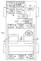
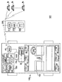
図1は、本発明の第1の実施形態の車両100に搭載された車両位置報知装置の構成を示したブロック図である。第1の実施形態の車両位置報知装置は、他の車両と自車両との相対位置をユーザに容易に把握させる為のものであり、装置全体の制御を統括して行う制御部10と、車両の位置情報及び向きを取得する為のGPS装置20と、記録媒体に記録された音楽データやラジオ放送などを再生する為のオーディオ部30と、同様の車両位置報知装置を搭載した車両と通信する為の通信部40を備えている。
FIG. 1 is a block diagram showing a configuration of a vehicle position notification device mounted on a
GPS装置20は、GPS用人工衛星から発信されたGPS信号を受信して位置情報を取得する為のGPSレシーバ21と、GPS装置20全体の制御を行う為のGPS用制御部22と、車両の角速度を計測するジャイロセンサ23と、車両の左右の駆動輪の回転速度を検出してその平均速度に応じた車速パルス信号を生成する車速センサ24と、デジタル地図データベースを含む各種データを記憶したメモリ25と、地図が表示される表示部26を備えている。
The
GPS用制御部22は、ジャイロセンサ23と車速センサ24から出力された信号に基づいてデッドレコニング(以下、DRと略記)を行う(すなわち車両の向き或いは進行方向及び距離を演算する)。そして、その演算したDR測位結果及びGPS測位結果を参照して、現在位置周辺のデジタル地図データをメモリ25から抽出し、それをD/A変換し、変換した地図データと共に車両の現在位置を示す自車両マークを表示部26に出力する。これによって例えば表示部26の中央部分に自車両マークが表示され、その画面全体に当該車両近辺の地図が表示される。
The
オーディオ部30は、各種音情報を再生する為の機構に加えて、ユーザが各種操作をする為の操作部31と、ユーザの音声が入力されるマイク32と、車両100の車内102に設置された6つのスピーカ33〜38を備えている。ここで、左前スピーカ33は車内102前方の左側に設置されたスピーカであり、中央前スピーカ34は車内102前方の中央部に設置されたスピーカであり、右前スピーカ35は、左前スピーカ33及び中央前スピーカ34に対して運転席104を挟むように、車内102前方の右側に設置されたスピーカである。また、左後スピーカ36は車内102後方の左側に設置されたスピーカであり、中央後スピーカ37は車内102後方の中央部に設置されたスピーカであり、右後スピーカ38は、左後スピーカ36及び中央後スピーカ37に対して運転席104を挟むように、車内102後方の右側に設置されたスピーカである。なお、車内102前方に設置された3つのスピーカと、車内102後方に設置された3つのスピーカとが、運転席104を挟んで設置されている。
In addition to a mechanism for reproducing various sound information, the audio unit 30 is installed in an operation unit 31 for a user to perform various operations, a microphone 32 to which a user's voice is input, and an
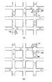
図2は、第1の実施形態の車両位置報知装置の作用を説明する為のブロック図である。図2には、道路に沿って矢印A方向に走行している車両100、車両110、及び他の複数台の車両が示されている。この車両110は、車両100と同様の車両位置報知装置を備えており、後述の相対位置報知処理を車両100との間で果たす。なお、図2(a)は時刻T1における各車両の位置を示した図であり、図2(b)は時刻T1から所定時間経過した時刻T2における各車両の位置を示した図である。
FIG. 2 is a block diagram for explaining the operation of the vehicle position notification device of the first embodiment. FIG. 2 shows a
図2(a)を参照すると、時刻T1において、車両110は道路に沿って建設された建物200の脇を走行しており、車両100は、複数台の車両を挟んで車両110の後方に位置する為、建物200から離れた地点を走行している状態にある。また、図2(b)を参照すると、時刻T2において、車両100は道路に沿って建設された建物200の脇を走行しており、車両110は、複数台の車両を挟んで車両100の前方に位置する為、建物200から離れた地点を走行している状態にある。
Referring to FIG. 2 (a), at time T 1, the
時刻T1において車両100と車両110とが例えば周知の相対位置検知処理を行った場合、車両100は、車両110との相対距離及びその車両が建物200近傍を走行中であるという情報を取得することができる。しかしながら周辺の地理に明るくないユーザは、これらを示した音声情報だけでは車両110との相対位置を把握できない。この為、結局、表示画面上の地図を参照しなければならない。また、周辺の地理に明るいユーザであっても、これらの音声情報だけで、車両110が自身に対してどの方向に位置しているかを迅速に判断することは難しいと考えられる。時刻T2においても同様の事態が想定される。
If the
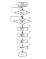
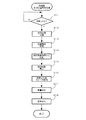
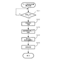
図3及び図4は、第1の実施形態の車両位置報知装置の制御部10で実行される処理であって、車両間の相対位置をユーザに報知する相対位置報知処理を示したフローチャートである。図3は自身の位置情報を相手側に送信する車両(ここでは車両110)で実行される送信側相対位置報知処理を示したフローチャートであり、図4は送信側からの情報を受信してそれとの相対位置をユーザに報知する車両(ここでは車両100)で実行される受信側相対位置報知処理を示したフローチャートである。以下に、図3及び図4を参照して、第1の実施形態の相対位置報知処理について説明する。なお、車両110の構成要素は車両100と同一である。説明を簡単にする為に、車両110の各構成要素にも車両100の各構成要素と同一の符号を付し、ここでの詳細な説明は省略する。
3 and 4 are flowcharts showing a relative position notification process that is executed by the
先ず、車両110の制御部10が実行する送信側相対位置報知処理について説明する。車両位置報知装置に電源電圧が供給されると、車両110の制御部10は、その操作部31に設けられたボタンであって、相対位置報知処理を実行する為の図示しない設定ボタンがオンされているか否かを判定する(ステップ1、以下、ステップを「S」と略記)。ここで、上記設定ボタンがオフされている場合(S1:NO)、車両110の制御部10は、S1のオン/オフ判定処理を繰り返し実行する。
First, the transmission side relative position notification process executed by the
上記設定ボタンがオンされている場合(S1:YES)、車両110の制御部10は、次に、送信先IDが設定されているか否かを判定する(S2)。この送信先IDとは自身の位置情報の送信先のID情報であり、ここでは車両100のID情報がそれに該当する。ここで、送信先IDが設定されていない場合(S2:NO)、車両110の制御部10は、S2の設定判定処理を繰り返し実行する。
When the setting button is turned on (S1: YES), the
送信先IDが設定されている場合(S2:YES)、車両110の制御部10は、他の車両に送信される音声信号を各構成要素を用いて生成する(S3)。なお、ここで生成される音声信号は、車両110のマイク32により入力されたユーザの音声をオーディオ部30の作用により符号化させたものであってもよいし、周知のナビゲーション装置で実施されているような位置情報とデジタル地図データを参照して生成された位置情報を音声信号に変換したものであってもよい。
When the transmission destination ID is set (S2: YES), the
音声信号が生成されると、車両110の制御部10は、車両110の現在位置情報をGPS装置20から取得する(S4)。そして、設定されている送信先IDと、自身のIDと、音声信号と、車両110の現在位置情報とを重畳し(S5)、通信部40を用いて車両100に送信して(S6)、本処理を終了させる。
When the audio signal is generated, the
次に、車両100の制御部10が実行する受信側相対位置報知処理について説明する。車両位置報知装置に電源電圧が供給されると、車両100の制御部10は、通信部40により他の車両からの信号を受信したか否かを判定する(S11)。ここで、他の車両からの信号を受信していないと判定した場合(S11:NO)、車両100の制御部10は、S11の受信待機処理を繰り返し実行する。また、他の車両からの信号を受信(ここでは車両110からの上記信号を受信)したと判定した場合(S11:YES)、車両100の制御部10は、受信した信号を、音声信号と車両110の位置情報とに分離する(S12)。
Next, the reception side relative position notification process executed by the
ここで、これらの車両は例えば無線LANや電話回線などを利用して接続される。電話回線を利用してこれらを接続する場合、各車両は、全二重伝送の回線を一回線分有している。なお、3台以上の車両で本処理を実行する場合、各車両はそれぞれとの通信を時分割で実行する。また、複数回線分有していれば、各車両は、それぞれとの通信を時分割で実行する必要がなくなる。 Here, these vehicles are connected using, for example, a wireless LAN or a telephone line. When these are connected using a telephone line, each vehicle has one full-duplex transmission line. When this process is executed by three or more vehicles, each vehicle executes communication with each other in a time division manner. Further, if a plurality of lines are provided, each vehicle need not perform communication with each other in a time division manner.
車両100の制御部10は、次に、車両100の現在位置情報及びその向きをGPS装置20から取得する(S13)。そして、車両100の位置情報と車両110の位置情報とを、メモリ25に格納されたデジタル地図データを参照して比較し(S14)、車両100に対する車両110の相対位置を算出する(S15)。なお、ここで算出される相対位置は、少なくとも、相対距離と、車両100に対して車両110が位置する方向とを含んだものである。
Next, the
相対位置が算出されると、車両100の制御部10は、車内102の音場がその相対位置に対応するよう定位させる。具体的には、車両100の制御部10は、S13の処理で取得した車両100の向きを示す情報と算出された相対位置に基づいて、当該相対位置に対応した位置に設置されたスピーカを、上記音声信号による音声を出力するスピーカとして設定する(S16)。そしてさらに、算出された相対距離に応じて、設定されたスピーカから出力される音声の音量も設定する(S17)。ここでは、運転席104を挟んだ一対のスピーカの各々の音量のバランスを、算出された相対距離に応じて設定する。
When the relative position is calculated, the
車両100の制御部10は、次に、オーディオ部30を駆動制御し、S2の処理で生成した音声信号を音声として出力できるよう処理を施す。そしてその音声を、S16の処理で設定されたスピーカから、S17で設定された音量で出力させ(S18)、本処理を終了させる。
Next, the
図2(a)に示した状態を一例として挙げると、車両110は車両100の右側の前方に位置している為、当該車両100の制御部10は、車両110との相対距離(例えば100m)、及び車両110が右側前方に位置したことを示した相対位置を算出する。ここで車両110が位置した方向が右側前方である為、それに対応した位置、すなわち車両100の車内102の右側前方に設置された右前スピーカ35及びそれと運転席104を挟んで配置された左後スピーカ36を音声を出力させるスピーカとして設定する。このとき相対距離が比較的遠い為、左後スピーカ36の音量を右前スピーカ35の音量より多少大きくする。そして車両110との相対距離や建物200近傍を走行中であることを示した音声を、それぞれ異なった音量で右前スピーカ35及び左後スピーカ36の各々から出力する。これにより車両100のユーザは、車両110との相対距離及び当該車両110が自身に対してどの方向(ここでは右側前方)に位置しているかを迅速に判断できる。従って例えば周辺の地理に明るくなくても、車両100のユーザは、音声が出力されたスピーカの位置及び音量のバランスによって車両110が位置する方向及び距離が判断できる為、車両110と逸れることがない。
Taking the state shown in FIG. 2A as an example, since the
また、図2(b)の状態において車両100が送信側で車両110が受信側である場合、当該車両110の制御部10は、車両100との相対距離(例えば10m)、及び車両100が後方に位置したことを示した相対位置を算出する。この為、車両110の制御部10は、それに対応した位置、すなわちその車内102の後方の中央部に設置された中央後スピーカ37及びそれと運転席104を挟んで配置された中央前スピーカ34を音声を出力するスピーカとして設定する。このとき相対距離が比較的近い為、中央前スピーカ34の音量を中央後スピーカ37の音量より多少大きくする。そして車両100との相対距離や建物200近傍を走行中であることを示した音声を、それぞれ異なった音量で中央前スピーカ34及び中央後スピーカ37の各々から出力する。これにより車両110のユーザは、車両100との相対距離及び当該車両100が自身に対してどの方向(ここでは後方)に位置しているかを迅速に判断できる。
2B, when the
なお、各スピーカの音量のバランスは、相対距離を変数とした線形関数により決定されるものであってもよいし、相対距離に応じて段階的に決定されるものであってもよい。 Note that the volume balance of each speaker may be determined by a linear function with the relative distance as a variable, or may be determined in stages according to the relative distance.
図5は、本発明の第2の実施形態の車両位置報知システム500の構成を示したブロック図である。第2の実施形態の車両位置報知システム500は、サーバを利用して車両間における相対位置をユーザに容易に把握させる為のものであり、サーバ300と、上述の如き車両位置報知装置を備えた複数台の車両から構築される。なお、複数台の車両は、車両100z及び車両M1〜Mnからなり、それぞれ同一の構成を有している。説明を簡単にする為に、以下においては車両100zについてのみ説明して他の車両M1〜Mnについては省略する。また、図5に示した車両100zにおいて、図1に示した車両100と同一の構成には、同一の符号を付してここでの詳細な説明は省略する。
FIG. 5 is a block diagram showing a configuration of a vehicle
車両位置報知システム500で用いられる装置であって、車両100zに備えられた車両位置報知装置は、装置全体の制御を統括して行う制御部10zと、車両の位置情報及び向きを取得する為のGPS装置20zと、オーディオ部30と、通信部40を備えている。GPS装置20zは、第1の実施形態のGPS装置20が有したメモリ25をメモリ25zに置き換えたものである。メモリ25zは、GPS装置20で用いられる各種データを記憶しているが、メモリ25と異なりデジタル地図データベースを記憶していない。また、以下に示されるように、制御部10zは、制御部10と異なった処理を実行するものである。
An apparatus used in the vehicle
サーバ300は、主たる機能として、各車両との通信機能、各車両間における相対位置の算出機能、及び各車両における音声出力させるスピーカの設定機能を有しており、各車両と通信する為の通信部310と、サーバ全体の制御を統括して行う制御部320と、各地域の地図データを蓄積した地図データベース330を備えている。なお、第1の実施形態と同様に、サーバ300と各車両は、例えば無線LANや電話回線などを利用して接続される。第2の実施形態において電話回線を利用してこれらを接続する場合には、車両が3台以上あっても、各車両は、一回線分有していればよく、それぞれと時分割で通信する必要がない。
The
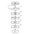
図6は、第2の実施形態のサーバ300の制御部320で実行される処理であって、車両間の相対位置を算出する相対位置算出処理を示したフローチャートである。また、図7は、サーバ300からの信号に基づいて他の車両との相対位置をユーザに報知する車両(ここでは車両100z)で実行される受信側相対位置報知処理を示したフローチャートである。以下に、図6及び図7を参照して、第2の実施形態の各構成要素で実行される処理について説明する。
FIG. 6 is a flowchart illustrating a relative position calculation process that is executed by the
先ず、各車両(ここでは車両100z、車両M1、及び車両M2)が図3のフローチャートで示された送信側相対位置報知処理と同様の処理を行うことにより、車両位置報知システム500における相対位置報知処理が開始される。ただし第2の実施形態では、S6に該当する処理における信号の送信先はサーバ300となる。
First, each vehicle (here, the
電源電圧供給状態であるとき、サーバ300の制御部320は、図6のフローチャートに示されるように車両からの信号を受信したか否かを判定している(S21)。ここで、車両からの信号を受信していないと判定した場合(S21:NO)、制御部320は、S21の受信待機処理を繰り返し実行する。また、車両からの信号を受信(ここでは車両100z、車両M1、及び車両M2からの上記信号を受信)したと判定した場合(S21:YES)、制御部320は、受信した信号の各々を、音声信号と位置情報とに分離する(S22)。
When in the power supply voltage supply state, the
制御部320は、次に、各車両の位置情報を、地図データベース330に格納されたデジタル地図データを参照して比較し(S23)、各車両の相対位置を算出する(S24)。なお、ここで算出される相対位置は、車両100zに対する車両M1と車両M2の各々の相対距離及びそれぞれが位置する方向を含んだ情報、車両M1に対する車両100zと車両M2の各々の相対距離及びそれぞれが位置する方向を含んだ情報、及び車両M2に対する車両100zと車両M1の各々の相対距離及びそれぞれが位置する方向を含んだ情報である。
Next, the
相対位置が算出されると、制御部320は、これらの相対位置を対応する音声信号と共に、各車両に送信する(S25)。
When the relative positions are calculated, the
次に、サーバ300からの信号を受信した車両の制御部(ここでは車両100zの制御部10z)が実行する受信側相対位置報知処理について説明する。車両位置報知装置に電源電圧が供給されると、制御部10zは、通信部40によりサーバ300からの信号を受信したか否かを判定する(S31)。ここで、サーバ300からの信号を受信していないと判定した場合(S31:NO)、制御部10zは、S31の受信待機処理を繰り返し実行する。また、サーバ300からの信号を受信したと判定した場合(S31:YES)、制御部10zは、受信した信号を、音声信号と相対位置の信号とに分離する(S32)。そして車両100zの向きをGPS装置20zから取得し、その向きの情報と分離された相対位置の信号に基づいて音声を出力するスピーカを設定し(S33)、第1の実施形態と同様にその音量を設定する(S34)。この実施形態では、サーバ300からの信号には、車両M1との相対位置を示した情報と、車両M2との相対位置を示した情報が含まれている。この為、S33の処理において制御部10zは、車両M1との相対位置を示した音声を出力するスピーカと、車両M2との相対位置を示した音声を出力するスピーカを設定する。スピーカが設定されると、制御部320は、それぞれの音声を、設定されたスピーカから設定された音量で出力し(S35)、本処理を終了させる。これら音声の内容及び各音声が出力されたスピーカの位置及び音量により、車両100zのユーザは、車両M1及び車両M2との相対位置を迅速に把握することができる。
Next, the reception-side relative position notification process executed by the vehicle control unit (here, the control unit 10z of the
以上が本発明の実施形態である。本発明はこれらの実施形態に限定されるものではなく様々な範囲で変形が可能である。 The above is the embodiment of the present invention. The present invention is not limited to these embodiments and can be modified in various ranges.
なお、第1及び第2の実施形態では1つのスピーカを用いてある車両との相対位置を報知しているが、別の実施形態では複数のスピーカを組み合わせて前記報知を実行してもよい。例えば車両100の右側に相手車両が位置しているときに右前スピーカ35と右後スピーカ38の両方から音声を出力させると、車両100のユーザは、自身の右側に相手が位置していることを迅速に把握できると考えられる。また、例えば相手車両の位置が車両100の右側であり且つ若干前側であるとき、右前スピーカ35と右後スピーカ38の両方から音声を出力させつつもそれらの音量に積極的に差を与えてもよい。この場合には、右前スピーカ35から出力される音声の音量を右後スピーカ38の音量より大きくする。このように各スピーカの音量に重み付けを与えることにより車両100のユーザは、相手側車両が右側且つ前側に位置していることを迅速に把握できる。このように音声を出力するスピーカの設定とそれぞれの音量設定とを複合的に組み合わせることにより、車両位置報知装置は、車両100のユーザに、さらに正確に相手側車両の位置する方向を把握させることができる。
In the first and second embodiments, a single speaker is used to notify the relative position to a vehicle. However, in another embodiment, the notification may be executed by combining a plurality of speakers. For example, when the opponent vehicle is located on the right side of the
またさらに、各スピーカから音声が出力されるタイミングを意図的にずらすことにより、ユーザに相手側車両の位置を報知する方法もある。例えば相手側車両が前方に位置している場合、先ず車内の前方に設置されたスピーカから音声を出力させ、僅かに遅延させて後方のスピーカから同一の音声を出力させる。このように音声を出力させると、前方に相手側車両が位置していることをユーザが感覚的に理解できることが想定される。 Furthermore, there is a method of notifying the user of the position of the counterpart vehicle by intentionally shifting the timing at which sound is output from each speaker. For example, when the counterpart vehicle is positioned in front, first, the sound is output from a speaker installed in front of the vehicle, and the same sound is output from the rear speaker with a slight delay. When the sound is output in this manner, it is assumed that the user can sensuously understand that the opponent vehicle is located ahead.
また、第1及び第2の実施形態の車両位置報知装置は車内102の前方と後方とで向かい合うよう設置された3対のスピーカを備えているが、少なくとも一対あればよく、これらのスピーカの数及び位置はこの形態に限定されることなく様々なものが想定される。例えば運転席104を囲んだ仮想的な三角形の各頂点に該当する位置に設置されていてもよい(すなわち3つ)。
In addition, the vehicle position notification device according to the first and second embodiments includes three pairs of speakers installed so as to face the front and the rear of the
10 制御部
20 GPS装置
30 オーディオ部
33〜38 スピーカ
40 通信部
100、110 車両
300 サーバ
500 車両位置報知システム
DESCRIPTION OF
Claims (5)
他車両と通信する為の通信手段と、
自身の位置情報を取得する位置情報取得手段と、
自車内の周辺部に設置され、音情報を出力する複数の音情報出力手段と、
受信した他車両の位置情報と自身の位置情報とを比較し、それらの相対位置を算出する相対位置算出手段と、
自身の向きを検出する向き検出手段と、
算出された相対位置及び検出された向きに基づいて当該相対位置を報知させる音情報出力手段を少なくとも1つ設定する設定手段と、
設定された音情報出力手段を作動させる作動手段と、を備えたこと、を特徴とする車両位置報知装置。 In a vehicle position notification device that is mounted on a vehicle and notifies a relative position between itself and another vehicle,
Communication means for communicating with other vehicles;
Position information acquisition means for acquiring own position information;
A plurality of sound information output means installed in the periphery of the vehicle and outputting sound information;
Relative position calculation means for comparing the received position information of other vehicles with its own position information and calculating their relative position;
Direction detection means for detecting its own direction;
Setting means for setting at least one sound information output means for informing the relative position based on the calculated relative position and the detected orientation;
A vehicle position notification device, comprising: an operating means for operating the set sound information output means.
該ネットワークを介して該車両位置報知装置と通信可能に接続されており、受信した複数の位置情報の各々を比較してそれらの相対位置を算出する相対位置算出手段とを有し、算出した相対位置を各車両に送信するサーバと、を備えた車両位置報知システムであって、
前記車両位置報知装置の各々は、受信した相対位置及び検出された向きに基づいて音情報出力手段を少なくとも1つ設定し、設定した音情報出力手段によって当該相対位置を報知すること、を特徴とする車両位置報知システム。 A plurality of sound information output means for outputting sound information, position information acquisition means for acquiring own position information position information, direction detection means for detecting its own direction, and a network; A vehicle position notification device provided in each of a plurality of vehicles, having a communication means for communicating with an external device via, and transmitting the acquired position information to the external device;
The vehicle position notification device is communicably connected via the network, and has relative position calculation means for comparing each of the received plurality of position information and calculating their relative position, and calculating the calculated relative A server for transmitting a position to each vehicle, and a vehicle position notification system comprising:
Each of the vehicle position notification devices sets at least one sound information output means based on the received relative position and the detected direction, and notifies the relative position by the set sound information output means. Vehicle position notification system.
Priority Applications (1)
| Application Number | Priority Date | Filing Date | Title |
|---|---|---|---|
| JP2004102555A JP2005292881A (en) | 2004-03-31 | 2004-03-31 | Vehicle location reporting device and vehicle location reporting system |
Applications Claiming Priority (1)
| Application Number | Priority Date | Filing Date | Title |
|---|---|---|---|
| JP2004102555A JP2005292881A (en) | 2004-03-31 | 2004-03-31 | Vehicle location reporting device and vehicle location reporting system |
Publications (1)
| Publication Number | Publication Date |
|---|---|
| JP2005292881A true JP2005292881A (en) | 2005-10-20 |
Family
ID=35325788
Family Applications (1)
| Application Number | Title | Priority Date | Filing Date |
|---|---|---|---|
| JP2004102555A Pending JP2005292881A (en) | 2004-03-31 | 2004-03-31 | Vehicle location reporting device and vehicle location reporting system |
Country Status (1)
| Country | Link |
|---|---|
| JP (1) | JP2005292881A (en) |
Cited By (7)
| Publication number | Priority date | Publication date | Assignee | Title |
|---|---|---|---|---|
| WO2009063669A1 (en) * | 2007-11-15 | 2009-05-22 | Sony Corporation | Radio communication device, voice data reproducing method, and program |
| JP2010231339A (en) * | 2009-03-26 | 2010-10-14 | Denso It Laboratory Inc | Message communication apparatus, message communication method, message communication system, and message communication program |
| JP2011107964A (en) * | 2009-11-17 | 2011-06-02 | Hitachi Kokusai Electric Inc | Radio communication system |
| JP2012048748A (en) * | 2011-11-24 | 2012-03-08 | Denso It Laboratory Inc | Message communication apparatus, message communication method, message communication system and message communication program |
| JP2017097522A (en) * | 2015-11-20 | 2017-06-01 | 株式会社東芝 | Information transmission device, information transmission method and program |
| EP3535629A4 (en) * | 2016-11-07 | 2020-07-15 | Whelen Engineering Company, Inc. | METHOD AND CONNECTED DEVICES FOR FIRST AID AND OPERATIONS ON THE ROAD SIDE |
| JP2022502792A (en) * | 2018-10-22 | 2022-01-11 | イーベイ インク.Ebay Inc. | Vehicle-to-vehicle communication and notification |
Citations (6)
| Publication number | Priority date | Publication date | Assignee | Title |
|---|---|---|---|---|
| JPH08211885A (en) * | 1995-02-01 | 1996-08-20 | Fujitsu Ten Ltd | Speech processing device |
| JP2000242898A (en) * | 1999-02-22 | 2000-09-08 | Equos Research Co Ltd | Peripheral vehicle alert system |
| JP2001001851A (en) * | 1999-06-16 | 2001-01-09 | Honda Motor Co Ltd | Vehicle alarm system |
| JP2002190093A (en) * | 2000-12-22 | 2002-07-05 | Toyota Motor Corp | Vehicle alarm system and device |
| JP2004226189A (en) * | 2003-01-22 | 2004-08-12 | Mitsubishi Electric Corp | Car navigation system |
| JP2005134971A (en) * | 2003-10-28 | 2005-05-26 | Fujitsu Ten Ltd | Driving support apparatus |
-
2004
- 2004-03-31 JP JP2004102555A patent/JP2005292881A/en active Pending
Patent Citations (6)
| Publication number | Priority date | Publication date | Assignee | Title |
|---|---|---|---|---|
| JPH08211885A (en) * | 1995-02-01 | 1996-08-20 | Fujitsu Ten Ltd | Speech processing device |
| JP2000242898A (en) * | 1999-02-22 | 2000-09-08 | Equos Research Co Ltd | Peripheral vehicle alert system |
| JP2001001851A (en) * | 1999-06-16 | 2001-01-09 | Honda Motor Co Ltd | Vehicle alarm system |
| JP2002190093A (en) * | 2000-12-22 | 2002-07-05 | Toyota Motor Corp | Vehicle alarm system and device |
| JP2004226189A (en) * | 2003-01-22 | 2004-08-12 | Mitsubishi Electric Corp | Car navigation system |
| JP2005134971A (en) * | 2003-10-28 | 2005-05-26 | Fujitsu Ten Ltd | Driving support apparatus |
Cited By (8)
| Publication number | Priority date | Publication date | Assignee | Title |
|---|---|---|---|---|
| WO2009063669A1 (en) * | 2007-11-15 | 2009-05-22 | Sony Corporation | Radio communication device, voice data reproducing method, and program |
| JP2009141936A (en) * | 2007-11-15 | 2009-06-25 | Sony Corp | Wireless communication apparatus, audio data reproduction method, and program |
| JP2010231339A (en) * | 2009-03-26 | 2010-10-14 | Denso It Laboratory Inc | Message communication apparatus, message communication method, message communication system, and message communication program |
| JP2011107964A (en) * | 2009-11-17 | 2011-06-02 | Hitachi Kokusai Electric Inc | Radio communication system |
| JP2012048748A (en) * | 2011-11-24 | 2012-03-08 | Denso It Laboratory Inc | Message communication apparatus, message communication method, message communication system and message communication program |
| JP2017097522A (en) * | 2015-11-20 | 2017-06-01 | 株式会社東芝 | Information transmission device, information transmission method and program |
| EP3535629A4 (en) * | 2016-11-07 | 2020-07-15 | Whelen Engineering Company, Inc. | METHOD AND CONNECTED DEVICES FOR FIRST AID AND OPERATIONS ON THE ROAD SIDE |
| JP2022502792A (en) * | 2018-10-22 | 2022-01-11 | イーベイ インク.Ebay Inc. | Vehicle-to-vehicle communication and notification |
Similar Documents
| Publication | Publication Date | Title |
|---|---|---|
| CN102905941B (en) | Vehicle warning sound generating device and vehicle warning sound generating method | |
| JP4961807B2 (en) | In-vehicle device, voice information providing system, and speech rate adjusting method | |
| EP1589727A1 (en) | Mobile information terminal and communication system | |
| KR20080106537A (en) | Navigation apparatus and method for conveying information relationships | |
| JPH09133545A (en) | Navigation system | |
| WO2018012156A1 (en) | Content selection system, content playback device, content selection server, and content selection method | |
| JP4466700B2 (en) | In-vehicle communication device, in-vehicle communication method, in-vehicle communication program | |
| JP5728129B2 (en) | Acoustic device, output sound management device, terminal device, and output sound control method | |
| JP2012118011A (en) | Information processor, on-vehicle device, and information processing method | |
| JP2005292881A (en) | Vehicle location reporting device and vehicle location reporting system | |
| US20070115433A1 (en) | Communication device to be mounted on automotive vehicle | |
| JP2008114649A (en) | Horn controller | |
| JP2009064331A (en) | Onboard communication device, onboard communication method, and onboard communication program | |
| JP5279552B2 (en) | Navigation device for mobile phones | |
| WO2001001076A1 (en) | Navigation device | |
| WO2013145083A1 (en) | Audio device, sound output management device, terminal device and sound output control method | |
| JP2006133145A (en) | Handsfree system | |
| JPWO2012073328A1 (en) | Information generating apparatus, information generating method, information generating program, and server apparatus | |
| JPWO2007097143A1 (en) | Telephone response device and telephone response method | |
| JP6954198B2 (en) | Terminal devices, group communication systems, and group communication methods | |
| JP5211234B2 (en) | Vehicle recalling sound output control device and vehicle recalling sound output control method | |
| JP4353748B2 (en) | Navigation device | |
| JP2009064333A (en) | Onboard communication device, onboard communication method, and onboard communication program | |
| JP2012081962A (en) | Terminal device for controlling output of vehicle-like sound, server device, and method of controlling output of vehicle-like sound | |
| JP4955837B2 (en) | Vehicle recalling sound output control device and vehicle recalling sound output control method |
Legal Events
| Date | Code | Title | Description |
|---|---|---|---|
| A621 | Written request for application examination |
Free format text: JAPANESE INTERMEDIATE CODE: A621 Effective date: 20070301 |
|
| A131 | Notification of reasons for refusal |
Free format text: JAPANESE INTERMEDIATE CODE: A131 Effective date: 20100209 |
|
| A02 | Decision of refusal |
Free format text: JAPANESE INTERMEDIATE CODE: A02 Effective date: 20100618 |