JP2005292850A - Image forming apparatus - Google Patents
Image forming apparatus Download PDFInfo
- Publication number
- JP2005292850A JP2005292850A JP2005144136A JP2005144136A JP2005292850A JP 2005292850 A JP2005292850 A JP 2005292850A JP 2005144136 A JP2005144136 A JP 2005144136A JP 2005144136 A JP2005144136 A JP 2005144136A JP 2005292850 A JP2005292850 A JP 2005292850A
- Authority
- JP
- Japan
- Prior art keywords
- control circuit
- main body
- heated
- image forming
- forming apparatus
- Prior art date
- Legal status (The legal status is an assumption and is not a legal conclusion. Google has not performed a legal analysis and makes no representation as to the accuracy of the status listed.)
- Pending
Links
Images


Classifications
-
- H—ELECTRICITY
- H04—ELECTRIC COMMUNICATION TECHNIQUE
- H04N—PICTORIAL COMMUNICATION, e.g. TELEVISION
- H04N1/00—Scanning, transmission or reproduction of documents or the like, e.g. facsimile transmission; Details thereof
- H04N1/00912—Arrangements for controlling a still picture apparatus or components thereof not otherwise provided for
- H04N1/00928—Initialisation or control of normal start-up or shut-down, i.e. non failure or error related
-
- G—PHYSICS
- G03—PHOTOGRAPHY; CINEMATOGRAPHY; ANALOGOUS TECHNIQUES USING WAVES OTHER THAN OPTICAL WAVES; ELECTROGRAPHY; HOLOGRAPHY
- G03G—ELECTROGRAPHY; ELECTROPHOTOGRAPHY; MAGNETOGRAPHY
- G03G15/00—Apparatus for electrographic processes using a charge pattern
- G03G15/20—Apparatus for electrographic processes using a charge pattern for fixing, e.g. by using heat
-
- H—ELECTRICITY
- H04—ELECTRIC COMMUNICATION TECHNIQUE
- H04N—PICTORIAL COMMUNICATION, e.g. TELEVISION
- H04N1/00—Scanning, transmission or reproduction of documents or the like, e.g. facsimile transmission; Details thereof
- H04N1/23—Reproducing arrangements
- H04N1/29—Reproducing arrangements involving production of an electrostatic intermediate picture
- H04N1/295—Circuits or arrangements for the control thereof, e.g. using a programmed control device, according to a measured quantity
Landscapes
- Engineering & Computer Science (AREA)
- Multimedia (AREA)
- Signal Processing (AREA)
- Physics & Mathematics (AREA)
- General Physics & Mathematics (AREA)
- Fixing For Electrophotography (AREA)
- General Induction Heating (AREA)
- Control Or Security For Electrophotography (AREA)
Abstract
Description
本発明は、加熱源として誘導加熱手段を用いた画像形成装置に関する。 The present invention relates to an image forming apparatus using induction heating means as a heating source.
画像形成装置では、加熱源としてハロゲンランプ等を用いている。このランプを、ヒートローラの内側に配置してヒートローラを加熱する。そして、被定着材をヒートローラに加圧した状態で接触させるために、プレスローラをヒートローラに押し当てて回転させ、二つのローラの間に紙を通過させる。 In the image forming apparatus, a halogen lamp or the like is used as a heating source. This lamp is disposed inside the heat roller to heat the heat roller. Then, in order to bring the fixing material into contact with the heat roller in a pressed state, the press roller is pressed against the heat roller and rotated to pass the paper between the two rollers.
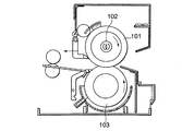
図8に、このような画像形成装置の概略構成を示す。薄肉の金属製のヒートローラ101の内側に、ハロゲンランプ102が配置されている。ヒートローラ101に被定着材を十分に加圧、接触させるために、プレスローラ103はその表面に弾性部材が配されている。そして、ヒートローラ101とプレスローラ103とは、図示されていない加圧機構によって所定の圧力を印加された状態で支持されている。さらに、図示されていない駆動源によって、被定着材の搬送速度と同一となるように、ヒートローラ101及びプレスローラ103がそれぞれ矢印の方向に回転する。
FIG. 8 shows a schematic configuration of such an image forming apparatus. A
ところが、ハロゲンランプ102を用いた装置では、熱効率が低く消費電力を低減させることが困難であった。また、電源を投入してから定着動作に必要な温度までヒートローラ101が上昇するまでに要するウォームアップタイムが長いという問題もあった。
However, in the apparatus using the
従って、本発明は熱効率が高く消費電力の低減が可能であると共に、電源投入から定着動作開始までの立ち上がりが速い画像形成装置を、簡易な手法により提供することを目的とする。 SUMMARY OF THE INVENTION Accordingly, an object of the present invention is to provide an image forming apparatus that has a high thermal efficiency and can reduce power consumption and that has a quick start-up from power-on to the start of a fixing operation, by a simple method.
本発明の画像形成装置は、
被加熱部材と、
前記被加熱部材に近接して配置され、電流を供給されて前記被加熱部材を誘導加熱する励磁コイルと、
前記励磁コイルへの電流の供給をオン/オフ制御する制御素子と、
前記制御素子に接続され、前記励磁コイルへの電流の供給を制御するための制御回路と、
この制御回路の動作を制御するCPUと、
前記被加熱部材の周囲温度を検知するサーミスタと、
前記サーミスタの出力を検知すると共に、画像形成装置全体の動作を制御する本体制御回路と、
を備え、
前記本体制御回路は、前記サーミスタからの出力に基づいて、複数の電源出力のなかからいずれか一つを選択し、電力制御信号を前記CPUに出力することを特徴とする。
The image forming apparatus of the present invention includes:
A heated member;
An excitation coil that is disposed in proximity to the member to be heated and that is supplied with a current to inductively heat the member to be heated;
A control element for on / off controlling the supply of current to the exciting coil;
A control circuit connected to the control element for controlling the supply of current to the exciting coil;
A CPU for controlling the operation of the control circuit;
A thermistor for detecting the ambient temperature of the heated member;
A main body control circuit for detecting the output of the thermistor and controlling the operation of the entire image forming apparatus;
With
The main body control circuit selects any one of a plurality of power supply outputs based on an output from the thermistor and outputs a power control signal to the CPU.
ここで、前記励磁コイル、あるいは回路の動作の異常を前記制御回路が検知した場合、異常検知信号を前記本体制御回路に出力することもできる。 Here, when the control circuit detects an abnormality in the operation of the exciting coil or circuit, an abnormality detection signal can be output to the main body control circuit.
前記励磁コイルに電流を供給するための電源と、前記電源と前記制御素子との間に接続され、且つ前記被加熱部材近傍に配置されたサーモスタットとをさらに備え、前記サーモスタットにより前記電源と前記制御素子との間が開閉されるようにしてもよい。 A power source for supplying current to the exciting coil; and a thermostat connected between the power source and the control element and disposed in the vicinity of the member to be heated; and the power source and the control by the thermostat You may make it open and close between elements.
以上説明したように、本発明の画像形成装置によれば、誘導加熱制御回路が本体制御回路と独立して中央処理装置を有することにより、本体制御回路による前記画像形成装置全体の動作の制御とは独立して励磁コイルへの電流の供給の制御が可能であるため、本体制御回路を含む電子写真装置の本体側のハードウェアを変更することなく、電磁誘導加熱手段の替わりにランプ加熱手段を用いることができる。 As described above, according to the image forming apparatus of the present invention, the induction heating control circuit has the central processing unit independently of the main body control circuit, thereby controlling the operation of the entire image forming apparatus by the main body control circuit. Can independently control the supply of current to the exciting coil, so that the lamp heating means can be used instead of the electromagnetic induction heating means without changing the hardware on the main body side of the electrophotographic apparatus including the main body control circuit. Can be used.
以下、本発明の一実施の形態について図面を参照して説明する。 Hereinafter, an embodiment of the present invention will be described with reference to the drawings.
本実施の形態は、被加熱部材を加熱する手段として、誘導加熱(Induction Heating)手段を用いる。さらに、ハロゲンランプ等のランプによる加熱手段と誘導加熱手段のいずれか一方を、ハードウェアの変更を伴うことなく選択することが可能な構成を備えている。 In the present embodiment, induction heating means is used as means for heating the member to be heated. Furthermore, it has a configuration in which either one of a heating unit using a lamp such as a halogen lamp or an induction heating unit can be selected without changing hardware.
本実施の形態による画像形成装置において、励磁コイル2への高周波電流の供給を制御する制御回路の構成を、図1に示す。
FIG. 1 shows the configuration of a control circuit that controls the supply of high-frequency current to the
電源29にSSR(Solid State Relay)27が接続され、SSR27は、サーモスタット26、整流回路28を介してインバータ駆動回路3に接続されている。
An SSR (Solid State Relay) 27 is connected to the
インバータ駆動回路3は励磁回路に相当し、整流回路28から電源を供給されて、励磁コイル2への高周波電流の供給をオン/オフ制御するIGBT(Insulated Gate Bi-Polar Transistor)4と、IGBT4のオン/オフ動作を制御するドライブIC5とを有する。
The
このインバータ駆動回路3は、インバータ制御回路7に接続されており、その駆動動作を制御される。
This
また、励磁コイル2には電流検知回路13が接続されており、励磁コイル2に流れる高周波電流が測定される。IGBT4の近傍にはサーミスタ6が配置されて周囲温度が検知される。IGBT4には、ファン12から必要に応じて送風されて加熱が防止される。
In addition, a
サーミスタ24が被加熱部材1の端部近傍に配置され、サーミスタ25がその中央近傍に配置されている。
The
インバータ制御回路7、電流検知回路13、ファン12、及びサーミスタ6はIH制御回路8に接続されており、それぞれの動作が制御される。IH制御回路8は、CPU(Central Processing Unit)9、ROM(Read Only Memory)10、RAM(Random access Memory)11を有している。ROM10には誘導加熱制御に必要なプログラムが予め格納されており、CPU9はこのプログラムに従って制御動作を行う。RAM11には制御処理に必要なデータが随時格納される。
The
IH制御回路8、サーミスタ24及び25、SSR27は、電子写真装置全体を制御する本体制御回路14に接続されている。
The
本体制御回路14は、各種オプションとしての機器を接続するためのインタフェースである各種オプション接続回路15に接続されている。また、電子写真装置が置かれている環境温度を検知するためのドラムサーミスタ23も本体制御回路14に接続されている。
The main
各種オプション機器としては、プリンタ16、FAX17、自動的に原稿を送るRADF(Reduction Auto Document Feeder)18、丁合を行うFIN(Finisher)19、給紙用の台車であるPFP(Paper Feeding Pedestal)20、大容量給紙台車であるLCF(Large Capacitor Feeder)21、さらにスキャナ、FAX、プリンタ等の単体として電子写真装置を用いるためのネットワークオプション22等が存在する。
Various optional devices include a
本体制御回路14から誘導加熱の開始を指示する加熱オン信号がIH制御回路8に与えられる。IH制御回路8は、インバータ駆動回路7の動作を制御し、これによりIGBT4から励磁コイル2に高周波電流が供給される。このときに必要な電源出力は、例えば700W、800W、850W、900W、1000W、1100W、1200W、1300Wのうちいずれか一つを、後述するように被加熱部材1の温度に応じて本体制御装置14が選択し、電力制御信号をIH制御回路8に出力する。
A heating-on signal instructing the start of induction heating is given to the
本実施の形態は、電子写真装置全体の制御を行う本体制御回路14とは独立して、誘導加熱を制御するIH制御回路8が内部にCPU9を有している。これにより、本体制御回路14は、IH制御回路8に対して加熱オン/オフ等の指令を与えればよい。IH制御回路8は、この指令を与えらた後は、本体制御回路14からは自立して誘導加熱手段の制御を行うことができる。
In the present embodiment, an
図2に、本体制御回路14とIH制御回路8との間で送受信される各種信号を示す。電力制御信号は、電力を700W〜1300Wのうちから選択するための信号であり、本体制御回路14からIH制御回路8に与えられる。加熱オン/オフ信号は、誘導加熱手段の加熱動作のオン/オフを指示する信号であり、本体制御回路14からIH制御回路8に与えられる。異常検知信号は、コイル異常、サーミスタ異常、回路動作の異常を検知した場合の信号であって、IH制御回路8から本体制御回路14に出力される。また、スリープ信号は、後述するように、電子写真装置が所定時間動作しない場合にスリープ状態に入ったことを示す信号であって、本体制御回路14からIH制御回路8に与えられる。
FIG. 2 shows various signals transmitted and received between the main
このような構成とすることで、ハードウェア構成を変更することなく、誘導加熱手段の替わりにランプ加熱手段を用いることも可能である。この場合の構成を、図3に示す。 With such a configuration, it is possible to use a lamp heating unit instead of the induction heating unit without changing the hardware configuration. The configuration in this case is shown in FIG.
電源29にSSR27が接続され、SSR27はサーモスタット26を介してハロゲンランプ102に接続されている。
The SSR 27 is connected to the
ハロゲンランプ102によって被加熱部材1が加熱される。被加熱部材1の端部及び中央部の温度は、二つのサーミスタ24、25によってそれぞれ測定される。
The member to be heated 1 is heated by the
また、SSR27の制御端子は、本体制御回路41の出力端子に接続されており、本体制御回路41の制御に基づいてハロゲンランプ102への給電が制御される。
The control terminal of the
ハロゲンランプ102を用いた場合は、上述したように熱効率が低く消費電力が大きい。また、電源を投入してから定着動作に必要な温度までヒートローラ101の温度が上昇するのに時間がかかる。しかし一方で、装置全体の価格は誘導加熱手段を用いた場合よりもランプ加熱手段を用いた装置の方が、低く抑えることができる。
When the
そこで、ハードウェア構成に変更を伴うことなく、ユーザがいずれか一方を自由に選択できるようにすることに意義がある。 Therefore, it is meaningful to allow the user to freely select either one without changing the hardware configuration.
ところで、被加熱部材1の温度とは無関係に、誘導加熱手段又はランプ加熱手段に対して一定の電力を供給すると、オーバシュート時の温度が許容範囲を超えて過熱するという問題がある。特に、近年では、電源投入時から定着可能な状態になるまでのウォームアップ時間を短縮するために、被加熱部材1の薄肉化や小径化を図っている。このような状態で、電源投入時において被加熱部材1がある程度加熱されて温度が摂氏0度よりも高いような場合には、一定電力を加熱手段に供給するとオーバシュートが過大になりやすい。
By the way, regardless of the temperature of the
図4の実線L1に示されたように、電源投入時における被加熱部材1の温度が摂氏0度である場合は、オーバシュート時の温度t2は定常時の温度t1に対して許容範囲内にある。ところが、電源投入時において、被加熱部材がある程度の温度t0を有する場合は、実線L1と同じ勾配を有する点線L2のように温度が上昇し、許容範囲を超えた温度t3までオーバシュートする。
As shown by the solid line L1 in FIG. 4, when the temperature of the
そこで本実施の形態では、被加熱部材1の近傍にサーミスタ24、25を配置して被加熱部材1の温度を検知し、この温度に応じて700W〜1300Wのなかから最適な電力を選択する。具体的には、サーミスタ24、25の出力を与えられた本体制御回路14が、検知された温度に基づいていずれかの電力を選択し、電力制御信号をIH制御回路8に出力する。
Therefore, in the present embodiment, the
図5に、被加熱部材1の温度と電力との関係を示す。このグラフに従って、被加熱部材1の温度に応じて、いずれの電力を選択する。
FIG. 5 shows the relationship between the temperature of the
この場合の処理の手順を、図6のフローチャートに示す。ステップS100として、電源投入時における被加熱部材1の温度を検知する。ステップS102において、被加熱部材1が摂氏0〜30度の範囲内にあるか否かを判断し、ある場合はステップS104として1300Wの電力を選択する。同様に、ステップS106において摂氏30〜75度の範囲内にあるか否かを判断し、ある場合はステップS108として1200Wを選択し、ステップS110において摂氏75〜110度の範囲内にあるか否かを判断し、ある場合はステップS112として1100Wを選択する。さらに、ステップS114において摂氏110〜150度の範囲内にあるか否かを判断し、ある場合はステップS116として1000Wを選択し、150度以上の場合はステップS118として900Wを選択する。いずれかの電力を選択して投入してから、所定時間が経過したか否かをステップS120において判断し、経過した場合はステップS122としてプレランプ処理としてドラムの空回転を行い、温度均一化を図る。
The processing procedure in this case is shown in the flowchart of FIG. As step S100, the temperature of the
このような、被加熱部材1の温度に応じた電力の可変制御は、ランプ加熱手段と誘導加熱手段のいずれを用いた場合にも、被加熱部材1の過熱を防止するのに有効である。特に、誘導加熱手段を用いる場合は、被加熱部材1の温度が急激に上昇するため、電力の可変制御を行うことは有効である。 Such variable control of the electric power according to the temperature of the member to be heated 1 is effective in preventing overheating of the member to be heated 1 regardless of whether the lamp heating unit or the induction heating unit is used. In particular, when the induction heating means is used, it is effective to perform variable power control since the temperature of the member to be heated 1 rises rapidly.
また、コイル異常やサーミスタ異常といった異常検知も、温度検知に基づいて行われる。このような異常検知処理においても、上述したように電源投入時の被加熱部材1の温度を検知して電力を選択することにより、温度勾配が緩やかになるので、より確実に温度を検知して異常の検知を確実に行うことができる。
Also, abnormality detection such as coil abnormality and thermistor abnormality is performed based on temperature detection. Even in such an abnormality detection process, as described above, the temperature gradient is moderated by detecting the temperature of the
ところで、画像形成装置では一般に、所定時間動作しなかった場合に、スリープモードに入る。特に、誘導加熱手段を用いた場合は、ウォームアップ時間が例えば30秒以内というように短いので、スリープモードに入って全ての機構をオフ状態にし、待機することが可能である。 By the way, the image forming apparatus generally enters a sleep mode when it has not been operated for a predetermined time. In particular, when the induction heating means is used, since the warm-up time is short, for example, within 30 seconds, it is possible to enter the sleep mode, turn off all the mechanisms, and wait.
この後、いずれかの処理を開始した場合、全ての機構にイニシャライズを行うと無駄な電力を消費することとなる。そこで、本実施例では、開始する処理の内容に応じて、必要な機構のみイニシャライズを行うようにしている。例えば、スリープモードにおいて、FAX送信のキーが押し下げられた場合は、スキャナ及びDF(Document Feeder)のみをイニシャライズし、他の不要な機構、例えば給紙、ドラムプロセス、定着機構を含む本体側のエンジンはオフする。 Thereafter, when any of the processes is started, if all the mechanisms are initialized, useless power is consumed. Therefore, in this embodiment, only necessary mechanisms are initialized in accordance with the contents of processing to be started. For example, in the sleep mode, when the FAX transmission key is pressed down, only the scanner and DF (Document Feeder) are initialized, and other unnecessary mechanisms such as a feed engine, a drum process, and a fixing mechanism are included. Turn off.
図7に示されたように、ステップS200において、所定時間非動作であったか否かが判定され、非動作であった場合はステップS202としてスリープモードに入る。スリープモードでは、ステップS204として、給紙機構、ドラムプロセス、スキャナ、DF、定着機構の全てがオフする。 As shown in FIG. 7, in step S200, it is determined whether or not it has been inactive for a predetermined time. If it has been inactive, it enters a sleep mode as step S202. In the sleep mode, in step S204, all of the paper feed mechanism, drum process, scanner, DF, and fixing mechanism are turned off.
ステップS206として、コピーキーが押し下げられた場合は、全ての機構の動作が必要である。そこで、ステップS208として全ての機構をイニシャライズし、ステップS210としてコピー処理を行う。 In step S206, when the copy key is depressed, all mechanisms need to be operated. Therefore, all mechanisms are initialized as step S208, and copy processing is performed as step S210.
ステップS212として、FAX送信のキーが押し下げられた場合は、ステップS214としてFAX送信に必要な機構のみ、即ちスキャナ、DFのみをイニシャライズする。そして、ステップS216としてFAX送信を行う。 If the FAX transmission key is depressed in step S212, only the mechanisms necessary for FAX transmission, that is, only the scanner and DF are initialized in step S214. In step S216, FAX transmission is performed.
ステップS218として、FAX受信、あるいはプリントデータの着信があった場合は、ステップS220としてFAX受信及びプリントデータの着信処理に必要な機構、即ち定着、給紙、ドラムプロセスをイニシャライズする。ステップS222として、FAX受信及びプリントデータの着信処理を行う。 If there is a FAX reception or an incoming print data in step S218, mechanisms required for the FAX reception and print data incoming processing, that is, fixing, paper feed, and drum process are initialized in step S220. In step S222, FAX reception and print data reception processing are performed.
このように、それぞれの処理に必要な機構のみをイニシャライズすることで、無駄な電力の消費を防ぐことができる。 In this way, wasteful power consumption can be prevented by initializing only the mechanisms necessary for each process.
また、上述したように、IGBT4に近接してサーミスタ6が配置されており、IGBT4の温度を検知している。本実施例では、このIGBT4の温度に応じて、必要な場合にのみファン12を回転させることで、消費電力を低減し、かつ騒音を低減する。また、IGBT4の温度が所定温度より上昇した場合は、IGBT4をオフさせて、誘導コイル2への電流の供給を停止させる。
Further, as described above, the
上述した実施の形態は一例であって、本発明を限定するものではない。例えば、誘導加熱手段を用いる場合の構成として図1に示された構成、ランプ加熱手段を用いる場合の構成として図2に示された構成は一例であり、必要に応じて様々な変形が可能である。 The above-described embodiment is an example and does not limit the present invention. For example, the configuration shown in FIG. 1 as the configuration when using the induction heating means and the configuration shown in FIG. 2 as the configuration when using the lamp heating means are examples, and various modifications are possible as necessary. is there.
1 被加熱部材
2 励磁コイル
3 インバータ駆動回路
4 IGBT
5 ドライブIC5
6 サーモスタット
7 インバータ制御回路
8 IH制御回路
9 CPU
10 ROM
11 RAM
12 ファン
13 電流検知回路
14 本体制御回路
15 各種オプション接続回路
16 プリンタ
17 FAX
18 RADF
19 FIN
20 PFP
21 LCF
22 ネットワークオプション
24、25 サーミスタ
26 サーモスタット
27 SSR
28 整流回路
29 電源
41 本体制御回路
102 ハロゲンランプ
1
5 Drive IC5
6
10 ROM
11 RAM
12
18 RADF
19 FIN
20 PFP
21 LCF
22
28
Claims (3)
前記被加熱部材に近接して配置され、電流を供給されて前記被加熱部材を誘導加熱する励磁コイルと、
前記励磁コイルへの電流の供給をオン/オフ制御する制御素子と、
前記制御素子に接続され、前記励磁コイルへの電流の供給を制御するための制御回路と、
この制御回路の動作を制御するCPUと、
前記被加熱部材の周囲温度を検知するサーミスタと、
前記サーミスタの出力を検知すると共に、画像形成装置全体の動作を制御する本体制御回路と、
を備え、
前記本体制御回路は、前記サーミスタからの出力に基づいて、複数の電源出力のなかからいずれか一つを選択し、電力制御信号を前記CPUに出力することを特徴とする画像形成装置。 A heated member;
An excitation coil that is disposed in proximity to the member to be heated and that is supplied with a current to inductively heat the member to be heated;
A control element for on / off controlling the supply of current to the exciting coil;
A control circuit connected to the control element for controlling the supply of current to the exciting coil;
A CPU for controlling the operation of the control circuit;
A thermistor for detecting the ambient temperature of the heated member;
A main body control circuit for detecting the output of the thermistor and controlling the operation of the entire image forming apparatus;
With
The image forming apparatus, wherein the main body control circuit selects any one of a plurality of power supply outputs based on an output from the thermistor and outputs a power control signal to the CPU.
前記電源と前記制御素子との間に接続され、且つ前記被加熱部材近傍に配置されたサーモスタットとをさらに備え、
前記サーモスタットにより前記電源と前記制御素子との間が開閉されることを特徴とする請求項1又は2記載の画像形成装置。 A power supply for supplying current to the exciting coil;
A thermostat connected between the power source and the control element and disposed near the heated member;
The image forming apparatus according to claim 1, wherein the thermostat opens and closes the power source and the control element.
Applications Claiming Priority (1)
| Application Number | Priority Date | Filing Date | Title |
|---|---|---|---|
| US09/473,061 US6321046B1 (en) | 1999-12-28 | 1999-12-28 | Induction heating fixing device having a central processing unit, and image forming apparatus using the fixing device |
Related Parent Applications (1)
| Application Number | Title | Priority Date | Filing Date |
|---|---|---|---|
| JP2003001440A Division JP2003202772A (en) | 1999-12-28 | 2003-01-07 | Induction heating fixing device and image forming apparatus using this fixing device |
Publications (1)
| Publication Number | Publication Date |
|---|---|
| JP2005292850A true JP2005292850A (en) | 2005-10-20 |
Family
ID=23878033
Family Applications (3)
| Application Number | Title | Priority Date | Filing Date |
|---|---|---|---|
| JP2000082818A Expired - Fee Related JP3400402B2 (en) | 1999-12-28 | 2000-03-23 | Induction heating fixing device and image forming apparatus using this fixing device |
| JP2003001440A Abandoned JP2003202772A (en) | 1999-12-28 | 2003-01-07 | Induction heating fixing device and image forming apparatus using this fixing device |
| JP2005144136A Pending JP2005292850A (en) | 1999-12-28 | 2005-05-17 | Image forming apparatus |
Family Applications Before (2)
| Application Number | Title | Priority Date | Filing Date |
|---|---|---|---|
| JP2000082818A Expired - Fee Related JP3400402B2 (en) | 1999-12-28 | 2000-03-23 | Induction heating fixing device and image forming apparatus using this fixing device |
| JP2003001440A Abandoned JP2003202772A (en) | 1999-12-28 | 2003-01-07 | Induction heating fixing device and image forming apparatus using this fixing device |
Country Status (2)
| Country | Link |
|---|---|
| US (1) | US6321046B1 (en) |
| JP (3) | JP3400402B2 (en) |
Families Citing this family (21)
| Publication number | Priority date | Publication date | Assignee | Title |
|---|---|---|---|---|
| US6509555B1 (en) * | 1999-11-03 | 2003-01-21 | Nexicor Llc | Hand held induction tool |
| US20030100340A1 (en) * | 2001-03-16 | 2003-05-29 | Cupps Bryan T. | Novel personal electronics device with thermal management |
| US6816688B2 (en) * | 2002-01-02 | 2004-11-09 | Kabushiki Kaisha Toshiba | Image forming apparatus |
| JP2005099711A (en) * | 2003-08-25 | 2005-04-14 | Ricoh Co Ltd | Fixing control apparatus, image forming apparatus, and fixing control method |
| US7323666B2 (en) | 2003-12-08 | 2008-01-29 | Saint-Gobain Performance Plastics Corporation | Inductively heatable components |
| KR100601893B1 (en) * | 2004-01-15 | 2006-07-19 | 삼성전자주식회사 | Image Forming Device and Power Saving Mode Control Method Using the Same |
| JP2005257945A (en) | 2004-03-10 | 2005-09-22 | Matsushita Electric Ind Co Ltd | Image heating device |
| US6875966B1 (en) * | 2004-03-15 | 2005-04-05 | Nexicor Llc | Portable induction heating tool for soldering pipes |
| US7102108B2 (en) * | 2004-03-15 | 2006-09-05 | Kabushiki Kaisha Toshiba | Induction-heating apparatus operating with power supplied in a select frequency range |
| US20050205559A1 (en) * | 2004-03-22 | 2005-09-22 | Kabushiki Kaisha Toshiba | Image forming apparatus |
| US7113736B2 (en) * | 2004-03-22 | 2006-09-26 | Kabushiki Kaisha Toshiba | Image forming apparatus |
| US7197253B2 (en) * | 2004-09-01 | 2007-03-27 | Konica Minolta Business Technologies, Inc. | Image forming apparatus including two CPUs to control a fixing device |
| US7205513B2 (en) | 2005-06-27 | 2007-04-17 | Xerox Corporation | Induction heated fuser and fixing members |
| JP2009042277A (en) * | 2007-08-06 | 2009-02-26 | Kyocera Mita Corp | Fixing device and image forming apparatus |
| JP5136113B2 (en) * | 2008-02-19 | 2013-02-06 | コニカミノルタビジネステクノロジーズ株式会社 | Image forming apparatus |
| US8155541B2 (en) * | 2009-04-08 | 2012-04-10 | Kabushiki Kaisha Toshiba | Fixing device which detects anomaly of heater |
| JP5253370B2 (en) * | 2009-12-28 | 2013-07-31 | 京セラドキュメントソリューションズ株式会社 | Induction heating apparatus and image forming apparatus |
| JP5514785B2 (en) | 2010-10-29 | 2014-06-04 | 京セラドキュメントソリューションズ株式会社 | Fixing apparatus and image forming apparatus having the fixing apparatus |
| JP5852320B2 (en) * | 2011-04-13 | 2016-02-03 | キヤノン株式会社 | Image forming apparatus and control method thereof |
| JP5304835B2 (en) * | 2011-04-20 | 2013-10-02 | コニカミノルタ株式会社 | Image forming apparatus and image forming method |
| JP6100625B2 (en) * | 2013-06-14 | 2017-03-22 | 株式会社沖データ | Fixing control device and image forming apparatus |
Family Cites Families (3)
| Publication number | Priority date | Publication date | Assignee | Title |
|---|---|---|---|---|
| US5752150A (en) | 1995-09-04 | 1998-05-12 | Minolta Co., Ltd. | Heating apparatus |
| US5794096A (en) * | 1995-10-25 | 1998-08-11 | Minolta Co., Ltd. | Induction type heat fixing device |
| JP3493448B2 (en) * | 1996-09-17 | 2004-02-03 | ミノルタ株式会社 | Induction heating fixing device |
-
1999
- 1999-12-28 US US09/473,061 patent/US6321046B1/en not_active Expired - Fee Related
-
2000
- 2000-03-23 JP JP2000082818A patent/JP3400402B2/en not_active Expired - Fee Related
-
2003
- 2003-01-07 JP JP2003001440A patent/JP2003202772A/en not_active Abandoned
-
2005
- 2005-05-17 JP JP2005144136A patent/JP2005292850A/en active Pending
Also Published As
| Publication number | Publication date |
|---|---|
| JP3400402B2 (en) | 2003-04-28 |
| US6321046B1 (en) | 2001-11-20 |
| JP2001222191A (en) | 2001-08-17 |
| JP2003202772A (en) | 2003-07-18 |
Similar Documents
| Publication | Publication Date | Title |
|---|---|---|
| JP2005292850A (en) | Image forming apparatus | |
| JP2925366B2 (en) | Image forming device | |
| US5875373A (en) | Image fixing device having means for controlling conveyance a transfer medium | |
| KR100644608B1 (en) | Apparatus and method for controlling power saving mode of electrical / electronic devices | |
| CN108388093B (en) | Temperature control of paper heating device | |
| JP2000293059A (en) | Image forming device | |
| CN101093380A (en) | Fixing device | |
| JP2006039049A (en) | FIXING DEVICE AND IMAGE FORMING DEVICE USING THE FIXING DEVICE AND ITS CONTROL METHOD | |
| US20050276625A1 (en) | Printing apparatus, fusing apparatus, and method of controlling fusing temperature of printing apparatus | |
| JP2009186601A (en) | Fixing device control device and image forming apparatus | |
| JP5921041B2 (en) | Image forming apparatus | |
| JPH05127565A (en) | Fixing device for image forming apparatus | |
| JPH08286549A (en) | Image forming device | |
| JP3308732B2 (en) | Fixing device controller | |
| JP2011033997A (en) | Image heating device | |
| JPH07287471A (en) | Fixing roller and fixing device | |
| US6993262B2 (en) | Fixing apparatus | |
| JP2007304362A (en) | Toner fixing device | |
| JP2005070628A (en) | Heater control device for fixing device | |
| JPH0668656B2 (en) | Image recorder | |
| US6858820B2 (en) | Fixing device | |
| US20240103414A1 (en) | Image forming apparatus and heating method | |
| JP4332397B2 (en) | Fixing device | |
| JPH03221983A (en) | Image forming device | |
| JP2001305904A (en) | Heating device and image forming device |
Legal Events
| Date | Code | Title | Description |
|---|---|---|---|
| A131 | Notification of reasons for refusal |
Free format text: JAPANESE INTERMEDIATE CODE: A131 Effective date: 20061205 |
|
| A02 | Decision of refusal |
Free format text: JAPANESE INTERMEDIATE CODE: A02 Effective date: 20070302 |
|
| A521 | Request for written amendment filed |
Free format text: JAPANESE INTERMEDIATE CODE: A523 Effective date: 20070502 |
|
| A911 | Transfer to examiner for re-examination before appeal (zenchi) |
Free format text: JAPANESE INTERMEDIATE CODE: A911 Effective date: 20070529 |
|
| A912 | Re-examination (zenchi) completed and case transferred to appeal board |
Free format text: JAPANESE INTERMEDIATE CODE: A912 Effective date: 20070622 |