JP2005292829A - Motion-based sound generation method and apparatus - Google Patents
Motion-based sound generation method and apparatus Download PDFInfo
- Publication number
- JP2005292829A JP2005292829A JP2005090386A JP2005090386A JP2005292829A JP 2005292829 A JP2005292829 A JP 2005292829A JP 2005090386 A JP2005090386 A JP 2005090386A JP 2005090386 A JP2005090386 A JP 2005090386A JP 2005292829 A JP2005292829 A JP 2005292829A
- Authority
- JP
- Japan
- Prior art keywords
- motion
- sensor
- movement
- signal
- motion pattern
- Prior art date
- Legal status (The legal status is an assumption and is not a legal conclusion. Google has not performed a legal analysis and makes no representation as to the accuracy of the status listed.)
- Pending
Links
Images
Classifications
-
- G—PHYSICS
- G10—MUSICAL INSTRUMENTS; ACOUSTICS
- G10H—ELECTROPHONIC MUSICAL INSTRUMENTS; INSTRUMENTS IN WHICH THE TONES ARE GENERATED BY ELECTROMECHANICAL MEANS OR ELECTRONIC GENERATORS, OR IN WHICH THE TONES ARE SYNTHESISED FROM A DATA STORE
- G10H1/00—Details of electrophonic musical instruments
- G10H1/0008—Associated control or indicating means
-
- G—PHYSICS
- G06—COMPUTING OR CALCULATING; COUNTING
- G06V—IMAGE OR VIDEO RECOGNITION OR UNDERSTANDING
- G06V10/00—Arrangements for image or video recognition or understanding
- G06V10/40—Extraction of image or video features
- G06V10/46—Descriptors for shape, contour or point-related descriptors, e.g. scale invariant feature transform [SIFT] or bags of words [BoW]; Salient regional features
-
- G—PHYSICS
- G10—MUSICAL INSTRUMENTS; ACOUSTICS
- G10H—ELECTROPHONIC MUSICAL INSTRUMENTS; INSTRUMENTS IN WHICH THE TONES ARE GENERATED BY ELECTROMECHANICAL MEANS OR ELECTRONIC GENERATORS, OR IN WHICH THE TONES ARE SYNTHESISED FROM A DATA STORE
- G10H2220/00—Input/output interfacing specifically adapted for electrophonic musical tools or instruments
- G10H2220/155—User input interfaces for electrophonic musical instruments
- G10H2220/395—Acceleration sensing or accelerometer use, e.g. 3D movement computation by integration of accelerometer data, angle sensing with respect to the vertical, i.e. gravity sensing
-
- G—PHYSICS
- G10—MUSICAL INSTRUMENTS; ACOUSTICS
- G10H—ELECTROPHONIC MUSICAL INSTRUMENTS; INSTRUMENTS IN WHICH THE TONES ARE GENERATED BY ELECTROMECHANICAL MEANS OR ELECTRONIC GENERATORS, OR IN WHICH THE TONES ARE SYNTHESISED FROM A DATA STORE
- G10H2220/00—Input/output interfacing specifically adapted for electrophonic musical tools or instruments
- G10H2220/155—User input interfaces for electrophonic musical instruments
- G10H2220/401—3D sensing, i.e. three-dimensional (x, y, z) position or movement sensing
Landscapes
- Engineering & Computer Science (AREA)
- Physics & Mathematics (AREA)
- Multimedia (AREA)
- Acoustics & Sound (AREA)
- Computer Vision & Pattern Recognition (AREA)
- General Physics & Mathematics (AREA)
- Theoretical Computer Science (AREA)
- Position Input By Displaying (AREA)
- Reverberation, Karaoke And Other Acoustics (AREA)
- User Interface Of Digital Computer (AREA)
Abstract
【課題】 動き基盤の音声発生方法および装置を提供する。
【解決手段】 所定装置の動きを感知し、感知された動きに対応する信号を生成するセンサー部10、前記生成された信号に基づいて所定装置の動きパターンを認識する動きパターン認識部20、および前記認識された動きパターンに対応する音声信号を生成する音声信号生成部30を含む動き基盤の音声発生装置を提供する。前記動きパターン認識部20は、前記センサー部で生成された信号をデジタル信号に変換するA/D変換部22、および前記変換されたデジタル信号に基盤して前記所定装置の動きパターンを分析する動きパターン分析部24を含む。前記音声信号生成部30は、前記所定装置の動きパターンとそれに対応する音声信号データを保存している保存媒体32、および所定の音声信号データに対応する音声信号を発生する信号発生部34を含む。
【選択図】 図1PROBLEM TO BE SOLVED: To provide a motion-based sound generation method and apparatus.
A sensor unit that detects a motion of a predetermined device and generates a signal corresponding to the detected motion, a motion pattern recognition unit 20 that recognizes a motion pattern of the predetermined device based on the generated signal, and A motion-based sound generation apparatus including an audio signal generation unit 30 that generates an audio signal corresponding to the recognized motion pattern is provided. The motion pattern recognition unit 20 includes an A / D conversion unit 22 that converts a signal generated by the sensor unit into a digital signal, and a motion that analyzes a motion pattern of the predetermined device based on the converted digital signal. A pattern analysis unit 24 is included. The audio signal generation unit 30 includes a storage medium 32 that stores the motion pattern of the predetermined device and the corresponding audio signal data, and a signal generation unit 34 that generates an audio signal corresponding to the predetermined audio signal data. .
[Selection] Figure 1
Description
本発明は、音声を発生させる方法および装置に係り、さらに詳細には、慣性センサーを利用して所定装置の動きパターンを認識し、その認識された動きパターンに対応する音声を発生させる、動き基盤の音声発生装置および動き基盤の音声発生方法に関する。以下、動きに基づいて音声を発生させる装置および方法を動き基盤の音声発生装置および動き基盤の音声発生方法と呼ぶ。 The present invention relates to a method and apparatus for generating sound, and more particularly, a motion base that recognizes a motion pattern of a predetermined device using an inertial sensor and generates a sound corresponding to the recognized motion pattern. The present invention relates to a sound generation apparatus and a motion-based sound generation method. Hereinafter, an apparatus and a method for generating sound based on motion are referred to as a motion-based sound generation apparatus and a motion-based sound generation method.
角速度センサーは、所定装置の角変化量を感知し、その感知した角変化量に対応するセンサー信号値を出力するセンサーであり、加速度センサーは、所定装置の速度変化量を感知し、その感知した速度変化量に対応するセンサー信号値を出力するセンサーである。角速度センサーや加速度センサー等の慣性センサーを利用して、3次元空間で所定装置の動きを認識し、認識された動きパターンに対応する文字、記号または所定の制御命令を入力する入力装置についての研究が進められている。 The angular velocity sensor is a sensor that detects the amount of change in the angle of a predetermined device and outputs a sensor signal value corresponding to the detected amount of change in the angle. The acceleration sensor detects the amount of change in velocity of the predetermined device. It is a sensor that outputs a sensor signal value corresponding to the speed change amount. Research on an input device that recognizes the motion of a given device in a three-dimensional space using an inertial sensor such as an angular velocity sensor or an acceleration sensor, and inputs characters, symbols, or a given control command corresponding to the recognized motion pattern Is underway.
ユーザの動きパターンは、ユーザごとに少しずつ異なるため、ユーザが正確な動きパターンで動かない場合に、前記動き基盤の入力装置にユーザの意図と全く異なる文字や制御命令が入力される場合が発生する。従来の動き基盤の入力装置では、特定文字や制御命令の入力中に、いかなる種類および内容の文字または制御命令が実際に入力されているか、ユーザ自身は、認識できない。特定文字や制御命令を完全に入力した後、入力装置の入力動作に対応する入力または制御の結果を通じて、ユーザ自身は、実際にいかなる内容および種類の文字や制御命令が入力されたかを認識できる。したがって、ユーザの所望する文字または制御命令が入力されていない場合に、最初から再び所定文字や制御命令を入力せねばならない不便さがあった。 Since the user's movement pattern is slightly different for each user, when the user does not move with an accurate movement pattern, characters or control commands that are completely different from the user's intention may be input to the movement-based input device. To do. In a conventional motion-based input device, the user himself / herself cannot recognize what type and contents of characters or control commands are actually input while inputting specific characters or control commands. After the specific character or control command is completely input, the user himself / herself can recognize what kind of content and type of character or control command is actually input through the input or control result corresponding to the input operation of the input device. Therefore, when a character or control command desired by the user is not input, there is an inconvenience that a predetermined character or control command must be input again from the beginning.
本発明が解決しようとする技術的課題は、所定装置の動きパターンを認識し、認識された動きパターンに対応する所定の音声を発生させる方法および装置、すなわち、動き基盤の音声発生方法および動き基盤の音声発生装置を提供することである。 A technical problem to be solved by the present invention is a method and apparatus for recognizing a motion pattern of a predetermined device and generating a predetermined sound corresponding to the recognized motion pattern, that is, a motion-based sound generation method and a motion base It is providing the audio | voice generating apparatus.
本発明が解決しようとする他の技術的課題は、前記動き基盤の音声発生方法をコンピュータで実行させるためのプログラム(プログラム製品)、および、そのプログラムを記録したコンピュータ可読記録媒体を提供することである。 Another technical problem to be solved by the present invention is to provide a program (program product) for causing a computer to execute the motion-based sound generation method, and a computer-readable recording medium recording the program. is there.
前記課題を解決するための本発明による動き基盤の音声発生装置は、音声発生装置の動きを感知し、感知された動きに対応する信号を生成するセンサー部、前記生成されたセンサー信号に基づいて前記音声発生装置の動きパターンを認識する動きパターン認識部および前記認識された動きパターンに対応する音声信号を生成する音声信号生成部を含むことを特徴とする。 According to an embodiment of the present invention, there is provided a motion-based sound generating device that detects a motion of a sound generating device and generates a signal corresponding to the detected motion, based on the generated sensor signal. A motion pattern recognition unit for recognizing a motion pattern of the sound generation device and a sound signal generation unit for generating a sound signal corresponding to the recognized motion pattern are included.
望ましくは、前記動きパターン認識部は、前記センサー部から出力されたセンサー信号をデジタル信号に変換するA/D(Analog to Digital)変換部、および前記デジタル信号に基づいて前記音声発生装置の動きパターンを分析する動きパターン分析部を含むことを特徴とする。 Preferably, the motion pattern recognition unit includes an A / D (Analog to Digital) conversion unit that converts a sensor signal output from the sensor unit into a digital signal, and a motion pattern of the sound generation device based on the digital signal. It includes a motion pattern analysis unit for analyzing.
望ましくは、前記音声信号生成部は、音声発生装置の動きパターンとそれに対応する音声信号データとを保存している保存媒体、および音声信号データに対応する音声信号を発生する信号発生部を含むことを特徴とする。 Preferably, the sound signal generation unit includes a storage medium that stores a motion pattern of the sound generation device and sound signal data corresponding to the motion pattern, and a signal generation unit that generates a sound signal corresponding to the sound signal data. It is characterized by.
望ましくは、前記動き基盤の音声発生装置は、前記音声信号生成部で生成された音声信号を出力する出力部をさらに含むことを特徴とする。 Preferably, the motion-based sound generation apparatus further includes an output unit that outputs the sound signal generated by the sound signal generation unit.
望ましくは、前記センサー部は、角速度センサー、加速度センサーまたはこれらの組合わせであることを特徴とする。 Preferably, the sensor unit is an angular velocity sensor, an acceleration sensor, or a combination thereof.
一方、前記課題を解決するための本発明による動き基盤の音声発生方法は、所定装置の動きを感知し、感知された動きに対応するセンサー信号を生成する段階、前記生成されたセンサー信号に基づいて前記所定装置の動きパターンを認識する段階および前記認識された動きパターンに対応する音声信号を生成する段階を含むことを特徴とする。 Meanwhile, the motion-based sound generation method according to the present invention for solving the above-described problem is based on detecting the motion of a predetermined device and generating a sensor signal corresponding to the detected motion, based on the generated sensor signal. Recognizing a motion pattern of the predetermined device and generating an audio signal corresponding to the recognized motion pattern.
望ましくは、前記所定装置の動きパターンを認識する段階は、前記センサー信号をデジタル信号に変換する段階、および前記デジタル信号に変換されたセンサー信号に基づいて前記所定装置の動きパターンを分析する段階を含むことを特徴とする。 Preferably, the step of recognizing the movement pattern of the predetermined device includes the step of converting the sensor signal into a digital signal and the step of analyzing the movement pattern of the predetermined device based on the sensor signal converted into the digital signal. It is characterized by including.
望ましくは、前記所定装置の動きパターンを分析する段階は、動きパターン認識表現変数を初期化する段階、前記センサー信号の値が所定臨界値を超過する時点を探知する段階、および前記探知された時点で前記動きパターン認識表現変数を所定値と設定する段階を含むことを特徴とする。 Preferably, analyzing the motion pattern of the predetermined device includes initializing a motion pattern recognition expression variable, detecting when the value of the sensor signal exceeds a predetermined critical value, and detecting the detected time And setting the motion pattern recognition expression variable to a predetermined value.
前記動き基盤の音声発生方法および装置を通じて、ユーザは、特定文字や信号または制御命令の入力中にもいかなる内容の文字や信号または制御命令が入力されているか分かる。また、本発明は、ユーザの特定の動きをユニークな音声で表現でき、したがって、常に新しさを追求する現代人の欲求を充足させることができる。 Through the motion-based sound generation method and apparatus, the user can understand what kind of character, signal, or control command is being input while the specific character, signal, or control command is being input. In addition, the present invention can express a user's specific movement with a unique voice, and thus can satisfy the desire of a modern person who always seeks newness.
以下、添付された図面を参照して、本発明の実施形態としての、動き基盤の音声発生方法および動き基盤の音声発生装置について詳細に説明する。 Hereinafter, a motion-based sound generation method and a motion-based sound generation device according to embodiments of the present invention will be described in detail with reference to the accompanying drawings.
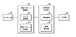
図1は、本発明の一実施形態としての動き基盤の音声発生装置を示すブロック図である。図1に示すように、前記動き基盤の音声発生装置は、センサー部10と、動きパターン認識部20と、音声信号生成部30と、出力部40とを含む。音声発生装置が動くと、センサー部10は、音声発生装置の動きを感知し、感知された動きに対応するセンサー信号値を出力する。動きパターン認識部20は、前記センサー部10から出力されたセンサー信号値に基づいて音声発生装置の動きパターンを認識する。前記音声信号生成部30は、前記動きパターン認識部で認識された動き基盤の音声発生装置の動きパターンに対応する音声信号を生成する。出力部40は、前記音声信号生成部30で生成された音声信号を受信してその音声信号に対応する音声を出力する。例えば、スピーカなどで構成される出力部40は、本発明が適用される応用分野によって一つ以上のスピーカを含んでいる。
FIG. 1 is a block diagram showing a motion-based sound generator as an embodiment of the present invention. As shown in FIG. 1, the motion-based sound generation device includes a
前記センサー部10は、本発明が応用される分野によって角速度センサー、加速度センサーまたはこれらの組合わせを含むものとして構成することができる。前記音声発生装置の動きに応じて音声発生装置の角速度および加速度は変化する。以下の記載において、音声発生装置の動きパターンは、音声発生装置の動きに応じて変化する角速度および加速度の変化パターンをいずれも含むものと定義する。角速度センサーは、前記音声発生装置の角速度、すなわち、前記音声発生装置の左右方向または上下方向または時計/逆時計回り方向の動きを感知し、感知された角速度に対応するセンサー信号値を生成する。前記角速度センサーを通じて音声発生装置の角速度を認識できる。加速度センサーは、前記音声発生装置の加速度、すなわち、音声発生装置の動き速度の変化を感知し、感知された加速度に対応するセンサー信号値を生成する。前記加速度センサーを通じて音声発生装置の加速度を認識できる。一方、前記センサー部10が角速度センサーと加速度センサーとの組合わせで構成されている場合には、音声発生装置の角速度および加速度をいずれも感知し、感知された角速度と加速度とに対応するセンサー信号値をそれぞれ生成する。
The
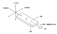
図2は、本発明の一実施形態としての動き基盤の音声発生装置を3次元空間で使用した場合の動きパターンを例示している。図2に示すように、前記動き基盤の音声発生装置は、それぞれ左右方向、上下方向および時計/逆時計回り方向の動きパターンを有する。前記3つの動きパターンを感知するために、前記音声発生装置は、音声発生装置の本体座標系上のx軸、y軸およびz軸方向にそれぞれ1個の角速度センサーまたは加速度センサーを備えている。前記x軸上に配置されている角速度センサーまたは加速度センサーは、それぞれ音声発生装置の上下方向の動きの角速度または左右方向の動きの加速度を感知する。前記y軸上に配置されている角速度センサーまたは加速度センサーは、それぞれ音声発生装置の時計/逆時計回り方向の動きの角速度または前後方向の動きの加速度を感知する。一方、z軸上に配置されている角速度センサーまたは加速度センサーは、それぞれ音声発生装置の左右方向の動きの角速度または上下方向の動きの加速度を感知する。 FIG. 2 exemplifies a motion pattern when a motion-based sound generation device according to an embodiment of the present invention is used in a three-dimensional space. As shown in FIG. 2, the motion-based sound generators have motion patterns in the left-right direction, the up-down direction, and the clockwise / counterclockwise direction. In order to sense the three movement patterns, the sound generator includes one angular velocity sensor or acceleration sensor in each of the x-axis, y-axis, and z-axis directions on the main body coordinate system of the sound generator. The angular velocity sensor or the acceleration sensor arranged on the x-axis senses the angular velocity of vertical movement or the acceleration of horizontal movement of the sound generator, respectively. The angular velocity sensor or the acceleration sensor arranged on the y-axis senses the angular velocity of the clockwise / counterclockwise movement or the acceleration of the movement in the front-back direction, respectively. On the other hand, the angular velocity sensor or the acceleration sensor arranged on the z axis senses the angular velocity of the movement of the sound generator in the left-right direction or the acceleration of the movement in the vertical direction, respectively.
また、前記動きパターン認識部20は、図1に示すように、アナログ電圧信号をデジタル信号に変換するA/D変換部22および音声発生装置の動きパターン認識アルゴリズムを実行する動きパターン分析部24を含む。前記センサー部10から出力されるセンサー信号は、前記動き基盤の音声発生装置の角速度または加速度値に対応するアナログ信号であり、A/D変換部22は、センサー部10から出力されるアナログセンサー信号値をデジタルセンサー信号値に変換する。A/D変換部22で変換されたデジタルセンサー信号値は、動きパターン分析部24に提供され、前記動きパターン分析部24は、提供されたデジタルセンサー信号値を利用して音声発生装置の動きパターンを分析するためのアルゴリズムを実行する。
Further, as shown in FIG. 1, the motion
前記音声信号生成部30は、音声発生装置の動きパターンとそれぞれの動きパターンに対応する音声信号データを保存(記憶)する保存媒体32、および所定の音声信号データに対応する信号を発生する信号発生部34を含む。前記動きパターン分析部24は、音声発生装置の動きパターンを分析すると、音声発生装置の動きパターンに対応する音声信号データを前記保存媒体32から抽出する。前記信号発生部34は、動きバターン分析部24で抽出された音声信号データに対応する音声信号を発生させる。出力部40は、音声信号生成部30の信号発生部34で発生させた音声信号を入力として所定の音声を出力する。
The
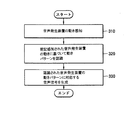
図3は、音声発生装置の動きに基づいて音声を発生させる方法を説明するためのフローチャートである。まず、310段階で、音声発生装置のセンサー部10によって、音声発生装置の動きが感知される。前述したように、前記センサー部10は、角速度センサーまたは加速度センサーまたはこれらの組合わせで構成されており、前記音声発生装置の動き角速度および/または加速度を測定する。前記センサー部10は、測定された音声発生装置の動きに対応するセンサー信号値を生成して動きパターン認識部20に出力する。次に、320段階で、前記感知された音声発生装置の動きに基づいて前記音声発生装置の動きパターンを認識する。前記音声発生装置の動きパターンを認識する段階(320)は、センサー部10で生成されたセンサー信号値をA/D変換部22でデジタルセンサー信号値に変換する段階と、前記デジタルに変換されたセンサー信号値を利用して動きパターン分析部24で前記音声発生装置の動きパターンを分析する段階と、を含む。前記音声発生装置の動きパターンを分析する段階についての詳細は、図4および図5を参照して、後述する。続いて、330段階で、前記認識された音声発生装置の動きパターンに対応する音声信号を生成する。前記音声信号生成段階は、認識された動きパターンに対応する音声信号データを保存媒体32から抽出する段階と、前記抽出された音声信号データに基づいて信号発生部34で音声信号を生成する段階と、を含む。
FIG. 3 is a flowchart for explaining a method of generating sound based on the movement of the sound generation device. First, in
図4は、本発明の一実施形態による角速度センサー10を備える動き基盤の音声発生装置で、その音声発生装置の動きパターンを分析する段階をさらに詳細に説明するためのフローチャートである。410段階で、3個の変数Tx、Ty、Tzの値を‘0’に初期化する。前記3個の変数は、動き基盤の音声発生装置の所定動きパターンを認識したか否かを示す(表現する)変数である。以下で、前記3個の変数を動きパターン認識表現変数と呼ぶ。前記動きパターン認識表現変数が‘0’と設定されているときは、所定大きさ以上の音声発生装置の動きが認知されていないということを表している。所定大きさ以上の音声発生装置の動きが認識されると、動きパターン認識表現変数が‘1’と設定される。420段階では、角速度センサー10で感知された音声発生装置の動きに対応するセンサー信号値から前記A/D変換部22によるA/D変換を通じてデジタルセンサー信号値を獲得する。前記角速度センサー10は、音声発生装置の動きの大きさに対応する測定値、例えば、電圧信号を生成し、前記生成された測定値は、下記の数式(1)を通じて角速度センサー信号値ωx,ωy,ωzとして計算される。
FIG. 4 is a flowchart for explaining in more detail the stage of analyzing the motion pattern of the sound generation device in the motion-based sound generation device including the
ここで、ωx、ωy、ωzは、音声発生装置の本体座標系の各軸(x軸、y軸、z軸)で測定した音声発生装置の角速度センサー信号値であり、Sx、Sy、Szは、音声発生装置の各軸に配置されている角速度センサーの敏感度を表す値であり、Vx、Vy、Vzは、音声発生装置の各軸に装着された角速度センサーから出力された電圧信号値であり、Vox、Voy、Vozは、音声発生装置の各軸に装着された角速度センサーの角速度値が‘0’である場合に出力される電圧信号値である。 Here, ω x , ω y , and ω z are the angular velocity sensor signal values of the sound generator measured on each axis (x axis, y axis, z axis) of the main body coordinate system of the sound generator, and S x , S y and S z are values representing the sensitivity of the angular velocity sensor arranged on each axis of the sound generator, and V x , V y and V z are angular velocities attached to each axis of the sound generator. The voltage signal value output from the sensor, and V ox , V oy , and V oz are voltage signal values output when the angular velocity value of the angular velocity sensor mounted on each axis of the sound generator is “0”. It is.
当業者であれば、前記数式(1)を通じて計算された角速度センサー信号値を利用する代わりに、前記角速度センサーで生成された測定値をそのまま使用して音声発生装置の動きパターンを認識できるということが容易に理解されるだろう。 A person skilled in the art can recognize the motion pattern of the sound generator by using the measurement value generated by the angular velocity sensor as it is, instead of using the angular velocity sensor signal value calculated through Equation (1). Will be easily understood.
430段階では、前記変換されたデジタルセンサー信号値と所定の臨界値Cx,Cy,Czとを比較して、前記デジタルセンサー信号値が所定の臨界値を超過する(430段階で「はい」となる)時点を探知する。前記所定の臨界値は、ユーザの動き分析を通じて決定される値であって、所定の音声を発生させるユーザの動きが小さな場合、前記臨界値は小さく設定され、一方、所定の音声を発生させるユーザの動きが大きい場合には、前記臨界値が大きく設定される。前記臨界値は、前記動き基盤の音声発生装置の製作時にあらかじめ特定値を設定しておくこともできるが、本願発明が適用される分野またはユーザの好みによって、ユーザが任意の値に調節できるよう構成することもできる。前記デジタルセンサー信号値が所定の臨界値を超過する(430段階で「はい」となる)時点で、音声発生装置の特定動きパターンが認識され、動いたパターン認識表現変数は‘1’と設定される。音声発生装置の上下、左/右、または時計/逆時計回り方向の動きは、以下の動き認識アルゴリズムで認識される。
In
(1)動き基盤の音声発生装置の上下方向の動きを認識する場合、|ωx(kx−1)|≦Cxから|ωx(kx)|>Cxに変わる時点kxを探知する。動き基盤の音声発生装置の上下方向の動きは、音声発生装置の本体座標系のx軸上に配置されている角速度センサーを使用して認識される。
(2)動き基盤の音声発生装置の左右方向の動きを認識する場合、|ωz(kz−1)|≦Czから|ωz(kz)|>Czに変わる時点kzを探知する。音声発生装置の左右方向の動きは、音声発生装置の本体座標系のz軸上に配置されている角速度センサーを使用して認識される。
(3)音声発生装置の時計/逆時計回り方向の動きを認識する場合、|ωy(ky−1)|≦Cyから|ωy(ky)|>Cyに変わる時点kyを探知する。音声発生装置の時計/逆時計回り方向の動きは、音声発生装置の本体座標系のy軸上に配置されている角速度センサーを使用して認識される。ここで、前記ωx、ωy、ωzは、角速度センサーから出力されたセンサー信号値であり、kx、ky、kzは、現在の離散時間値であり、kx−1、ky−1、kz−1は、現在の離散時間の直前の値である。
(1) When recognizing the vertical movement of a motion-based sound generator, the time point k x when | ω x (k x −1) | ≦ C x changes to | ω x (k x ) |> C x Detect. The vertical movement of the motion-based sound generator is recognized using an angular velocity sensor arranged on the x-axis of the main body coordinate system of the sound generator.
(2) When recognizing the left-right movement of the motion-based sound generator, the time point k z when | ω z (k z −1) | ≦ C z changes to | ω z (k z ) |> C z Detect. The movement of the sound generator in the left-right direction is recognized using an angular velocity sensor arranged on the z-axis of the main body coordinate system of the sound generator.
(3) When recognizing the clockwise / counterclockwise movement of the sound generator, the time point ky when | ω y (k y −1) | ≦ C y changes to | ω y (k y ) |> C y is determined. Detect. The movement of the sound generator in the clockwise / counterclockwise direction is recognized using an angular velocity sensor arranged on the y-axis of the main body coordinate system of the sound generator. Here, ω x , ω y , and ω z are sensor signal values output from the angular velocity sensor, k x , k y , and k z are current discrete time values, and k x −1, k y −1 and k z −1 are values immediately before the current discrete time.
440段階で、角速度センサーから出力されたセンサー信号値が前記所定の臨界値を超過するそれぞれの時点kx,ky,kzに、前記動きパターン認識表現変数Tx,Ty,Tzは、それぞれ‘1’と設定される。前記動きパターン認識表現変数が‘1’と設定される時点に、前記動き基盤の音声発生装置は、x軸、y軸またはz軸の動きパターンに対応するそれぞれの音声を発生させる。450段階で、角速度センサーから出力されるセンサー信号値が続いて入力されているかを判定する。センサー信号値が獲得され続けていれば(450段階で「はい」)、410段階に戻る。
In
一方、430段階で、角速度センサーから生成されたセンサー信号値を所定の臨界値と比較して、前記センサー信号値が所定の臨界値を超過しない場合には(430段階で「いいえ」)、420段階に戻る。
On the other hand, in
前記音声発生装置の動きパターンを分析する(1)、(2)、(3)のアルゴリズムでは、角速度センサーで生成されたセンサー信号値の絶対値を利用して、音声発生装置の動きパターンを認識している。したがって、左右方向、上下方向および時計/逆時計回り方向の動きをそれぞれ同一に認識する。しかし、絶対値を使用せずに音声発生装置の動きパターン分析アルゴリズムを実行することもできる。この場合、音声発生装置の本体座標系のx軸に配置されている角速度センサーは、音声発生装置の上方および下方の動きを、y軸に配置されている角速度センサーは、音声発生装置の時計/逆時計回り方向の動きを、そしてz軸に配置されている角速度センサーは、音声発生装置の左右方向の動きをそれぞれ区別して認識するよう構成することができる。 In the algorithms (1), (2), and (3) for analyzing the movement pattern of the voice generator, the movement pattern of the voice generator is recognized using the absolute value of the sensor signal value generated by the angular velocity sensor. doing. Therefore, the movements in the left-right direction, the up-down direction, and the clockwise / counterclockwise direction are recognized in the same way. However, it is also possible to execute the motion pattern analysis algorithm of the sound generator without using the absolute value. In this case, the angular velocity sensor disposed on the x-axis of the main body coordinate system of the sound generation device performs the upward and downward movements of the sound generation device, and the angular velocity sensor disposed on the y-axis represents the clock / clock of the sound generation device. The counterclockwise movement and the angular velocity sensor arranged on the z-axis can be configured to distinguish and recognize the left-right movement of the sound generator.
図5は、本発明の一実施形態による加速度センサー10を備える動き基盤の音声発生装置で、その音声発生装置の動きパターンを分析する段階をさらに詳細に説明するためのフローチャートである。510段階では、前記動き基盤の音声発生装置の動きパターン認識表現変数Tx,Ty,Tzを‘0’に初期化する。動きパターン認識表現変数についての定義は、前記図4を参照しつつ説明した通りである。520段階では、加速度センサー10で感知された音声発生装置の動きに対応するセンサー信号値から前記A/D変換部22によるA/D変換を通じてデジタル変換されたセンサー信号値Abx,Aby,Abzを獲得する。前記加速度センサー10は、音声発生装置の動きパターン大きさに対応する測定値、例えば、電圧信号を生成し、前記生成された測定値は、下記の数式(2)を通じて加速度センサー信号値Abx,Aby,Abzとして計算される。
FIG. 5 is a flowchart for explaining in more detail the stage of analyzing a motion pattern of the sound generation device in the motion-based sound generation device including the
ここで、Abx、Aby、Abzは、音声発生装置の本体座標系の各軸(x軸、y軸、z軸)で測定した音声発生装置の加速度センサー信号値であり、Sbx、Sby、Sbzは、音声発生装置の各軸に配置されている加速度センサーの敏感度を表す値であり、Vbx、Vby、Vbzは、音声発生装置の本体座標系の各軸に装着された加速度センサーで生成される測定値であり、Vbox、Vboy、Vbozは、音声発生装置の本体座標系の各軸に装着された加速度センサーの加速度値が‘0’である場合に生成される測定値である。 Here, A bx , A by , and A bz are acceleration sensor signal values of the sound generator measured on each axis (x axis, y axis, z axis) of the main body coordinate system of the sound generator, and S bx , S by and S bz are values representing the sensitivity of the acceleration sensor arranged on each axis of the sound generator, and V bx , V by and V bz are on each axis of the main body coordinate system of the sound generator. V box , V boy , and V boz are measurement values generated by the mounted acceleration sensor, and the acceleration value of the acceleration sensor mounted on each axis of the body coordinate system of the sound generator is “0”. Is the measurement value generated.
3次元空間上で動き基盤の音声発生装置は、常に重力加速度gを受けているため、530段階で、加速度センサーから生成されたセンサー信号値Abx,Aby,Abzを航法座標系(navigation coordinate system)のセンサー信号値Anx,Any,Anzに変換しなければならない。本体座標系センサー信号値を航法座標系センサー信号値に変換するためには、一般に、角速度センサーが必要である。しかし、本願発明では、ユーザが音声発生装置を動かす時、音声発生装置の姿勢は大きく変わらないという仮定下に、下記の数式(3)を使用して、本体座標系センサー信号値Abx,Aby,Abzを航法座標系センサー信号値Anx,Any,Anzに変換する。 Since the motion-based sound generator in the three-dimensional space always receives gravitational acceleration g, the sensor signal values A bx , A by , A bz generated from the acceleration sensor are displayed in the navigation coordinate system (navigation) in 530 stages. Coordinate system) sensor signal values A nx , A ny , A nz must be converted. In order to convert the main body coordinate system sensor signal value into the navigation coordinate system sensor signal value, an angular velocity sensor is generally required. However, in the present invention, when the user moves the sound generation device, the body coordinate system sensor signal values A bx , A are calculated using the following formula (3) under the assumption that the posture of the sound generation device does not change greatly. By and A bz are converted into navigation coordinate system sensor signal values A nx , A ny , and A nz .
ここで、φ、θ、ψはオイラー角であり、次の数式(4)、(5)、(6)によって計算される。 Here, φ, θ, and ψ are Euler angles, and are calculated by the following equations (4), (5), and (6).
540段階で、前記航法座標系に変換されたセンサー信号値と所定の臨界値Cbx,Cby,Cbzとを比較して、前記センサー信号値が所定の臨界値を超過する(540段階で「はい」となる)時点を探知する。前記センサー信号値が所定の臨界値を超過する時点に、音声発生装置の特定方向加速度が認識される。音声発生装置の上下、左右または前後方向の加速度は、下記のように認識される。
In
(1)音声発生装置の左右方向の加速度を認識する場合、|Anx(kx−1)|≦Cbxから|Anx(kx)|>Cbxに変わる時点kxを探知する。音声発生装置の左右方向の加速度は、音声発生装置の本体座標系のx軸上に配置されている加速度センサーを使用して認識される。
(2)音声発生装置の上下方向の加速度を認識する場合、|Anz(kz−1)|≦Cbzから|Anz(kz)|>Cbzに変わる時点kzを探知する。音声発生装置の上下方向の加速度は、音声発生装置の本体座標系のz軸上に配置されている加速度センサーを使用して認識される。
(3)音声発生装置の前後方向の加速度を認識する場合、|Any(ky−1)|≦Cbyから|Any(ky)|>Cbyに変わる時点kyを探知する。音声発生装置の前後方向の加速度は、音声発生装置の本体座標系のy軸上に配置されている加速度センサーを使用して認識される。ここで、kx、ky、kzは、現在の離散時間値であり、kx−1、ky−1、kz−1は、現在離散時間の直前の値である。550段階で、加速度センサーから出力されたセンサー信号値が前記所定臨界値を超過するそれぞれの時点Kx,Ky,Kzに動きパターン認識表現変数Tx,Ty,Tzは、それぞれ‘1’と設定される。前記動きパターン認識表現変数が‘1’と設定される時点に、前記動き基盤の音声発生装置は、x軸、y軸またはz軸の動きパターンに対応するそれぞれの音声を発生させる。
(1) When recognizing the acceleration in the left-right direction of the sound generator, the time point k x when | A nx (k x −1) | ≦ C bx changes to | A nx (k x ) |> C bx is detected. The acceleration in the left-right direction of the sound generator is recognized by using an acceleration sensor arranged on the x-axis of the main body coordinate system of the sound generator.
(2) When recognizing the vertical acceleration of the sound generator, the time point k z when | A nz (k z −1) | ≦ C bz changes to | A nz (k z ) |> C bz is detected. The vertical acceleration of the sound generator is recognized using an acceleration sensor arranged on the z-axis of the main body coordinate system of the sound generator.
(3) when recognizing an acceleration in the front-rear direction of the sound generation device, | A ny (k y -1 ) | from ≦ C by | A ny (k y) | to detect the time point k y vary to> C By. The acceleration in the front-rear direction of the sound generator is recognized by using an acceleration sensor arranged on the y-axis of the main body coordinate system of the sound generator. Here, k x , k y , and k z are current discrete time values, and k x −1, k y −1, and k z −1 are values immediately before the current discrete time. In
一方、540段階で、航法座標系センサー信号値を所定の臨界値と比較して、前記センサー信号値が所定の臨界値を超過しない場合には(540段階で「いいえ」)、520段階に戻る。560段階で、加速度センサーからセンサー信号値が続いて入力されているかを判定する。センサー信号値が獲得され続けていれば(560段階で「はい」)、510段階に戻る。
On the other hand, in
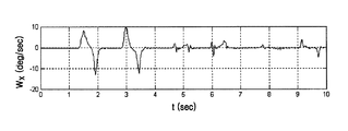
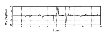
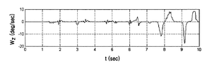
図6Aないし6Cは、本発明の一実施形態による角速度センサー10を備える動き基盤の音声発生装置が左右、上下または時計/逆時計回り方向に動く時、前記音声発生装置の角速度センサー10から生成された本体座標系の各軸の角速度値ωx,ωy,ωzを示している。図6Aは、x軸角速度センサー信号値ωx、図6Bは、y軸の角速度センサー信号値ωy、図6Cは、z軸の角速度センサー信号値ωzを示している。
FIGS. 6A to 6C are generated from the
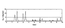
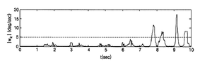
一方、図7Aないし7Cは、図6Aないし6Cに示されている角速度センサー信号値ωx,ωy,ωzの絶対値|ωx|,|ωy|,|ωz|とユーザ動きを分析して決定される所定の臨界値Cx,Cy,Czとを示している。図7Aは、x軸角速度センサー信号の絶対値|ωx|および臨界値Cx、図7Bは、y軸の角速度センサー信号の絶対値|ωy|および臨界値Cy、図7Cは、z軸の角速度センサー信号の絶対値|ωz|および臨界値Czを示している。 図7Aで、x軸角速度センサー信号の絶対値は、4個の離散時間で臨界値Cxを超過する。図7Bで、y軸角速度センサー信号の絶対値は、4個の離散時間で臨界値Cyを超過する。図7Cで、z軸角速度センサー信号の絶対値は、4個の離散時間で臨界値Czを超過する。 On the other hand, FIGS. 7A to 7C show the user movements with the absolute values | ω x |, | ω y |, | ω z | of the angular velocity sensor signal values ω x , ω y , ω z shown in FIGS. The predetermined critical values C x , C y , and C z determined by analysis are shown. 7A shows the absolute value | ω x | and the critical value C x of the x-axis angular velocity sensor signal, FIG. 7B shows the absolute value | ω y | and the critical value C y of the y-axis angular velocity sensor signal, and FIG. The absolute value | ω z | and the critical value C z of the axial angular velocity sensor signal are shown. In FIG. 7A, the absolute value of the x-axis angular velocity sensor signal exceeds the critical value C x in four discrete times. In Figure 7B, the absolute value of y-axis angular velocity sensor signal exceeds the threshold value C y at four discrete time. In FIG. 7C, the absolute value of the z-axis angular velocity sensor signal exceeds the critical value C z in four discrete times.
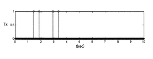
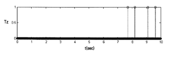
図8Aないし8Cは、前記動きパターン認識アルゴリズムを通じて、Tx、Ty、Tzの値が‘1’と設定される時の離散時間を示している。図8Aは、x軸角速度センサー信号の絶対値が所定の臨界値Cxを超過する離散時間を示している。図8Bは、y軸角速度センサー信号の絶対値が所定の臨界値Cyを超過する離散時間を示している。図8Cは、z軸角速度センサー信号の絶対値が所定の臨界値Czを超過する離散時間を示している。各軸で、角速度信号の絶対値が所定の臨界値を超過する時点に動きパターン認識表現変数Tx,Ty,Tzは、‘1’と設定される。 8A to 8C show discrete times when the values of T x , T y , and T z are set to “1” through the motion pattern recognition algorithm. FIG. 8A shows the discrete time when the absolute value of the x-axis angular velocity sensor signal exceeds a predetermined critical value C x . 8B is the absolute value of y-axis angular velocity sensor signal indicates a discrete time that exceeds the predetermined threshold value C y. FIG. 8C shows the discrete time when the absolute value of the z-axis angular velocity sensor signal exceeds a predetermined critical value C z . In each axis, the motion pattern recognition expression variables T x , T y , T z are set to “1” when the absolute value of the angular velocity signal exceeds a predetermined critical value.
図9は、2個の音声発生装置を利用してビットボックス(bit box)を具現する本発明の一実施形態を示している。図9に示すように、ユーザが音声発生装置を左右方向、上下方向または時計/逆時計回り方向に動かすか、または速いまたは遅い速度変化を伴う動きとなるように動かすと、前記音声発生装置の動きを感知し、感知された動きに基づいて音声発生装置の動きパターンを認識する。前記音声発生装置は、音声発生装置の動きパターンを認識し、認識された動きパターンに対応する音声を発生させる。音声発生装置1と音声発生装置2とは、動きパターンによってそれぞれ異なる音声を発生させるように製作することができる。図9は、音声発生装置の一実施形態を示す図面であり、前記音声発生装置が使われる分野によって多数の音声発生装置が使用され、それぞれの音声発生装置は、動きパターンによって異なる音声を発生させるように製作することができる。
FIG. 9 shows an embodiment of the present invention that implements a bit box using two sound generators. As shown in FIG. 9, when the user moves the sound generator in the left-right direction, the up-down direction, or the clockwise / counterclockwise direction, or moves in a motion with a fast or slow speed change, The movement is detected, and the movement pattern of the sound generator is recognized based on the detected movement. The voice generator recognizes a motion pattern of the voice generator and generates a voice corresponding to the recognized motion pattern. The
一方、前述した本発明の実施形態は、コンピュータで実行できるプログラムに作成可能であり、コンピュータ可読記録媒体を利用して保存、流通ないしインストールして、前記プログラムを動作させる汎用デジタルコンピュータ上で本発明を実現することができる。 On the other hand, the above-described embodiment of the present invention can be created in a computer-executable program, and is stored, distributed or installed using a computer-readable recording medium, and the present invention is executed on a general-purpose digital computer that operates the program. Can be realized.
前記コンピュータ可読記録媒体は、磁気記憶媒体(例えば、ROM(Read Only Memory)、フレキシブルディスク、ハードディスクなど)、光学的な記録媒体(例えば、CD−ROM、DVDなど)およびキャリアウェーブ(例えば、インターネットを通じた伝送)のような伝送(通信)媒体を含む。 The computer-readable recording medium includes a magnetic storage medium (for example, ROM (Read Only Memory), a flexible disk, a hard disk, etc.), an optical recording medium (for example, CD-ROM, DVD, etc.), and a carrier wave (for example, via the Internet). Transmission (communication) media, such as transmission.
本発明は、図面に示された実施形態を参考として説明されたが、これは、例示的なものに過ぎず、当業者ならば、これから多様な変形および均等な他の実施形態が可能であることが分かる。したがって、本発明の真の技術的保護範囲は、特許請求の範囲の技術的思想によって決定されねばならない。 Although the present invention has been described with reference to the embodiments shown in the drawings, this is merely exemplary, and various modifications and equivalent other embodiments can be made by those skilled in the art. I understand that. Therefore, the true technical protection scope of the present invention must be determined by the technical idea of the claims.
本発明は、携帯電話やPDAのような多様な携帯情報機器または打楽器の機能を有する装置などに適用できる。 The present invention can be applied to various portable information devices such as mobile phones and PDAs, or devices having percussion instrument functions.
10 センサー部
20 動きパターン認識部
22 A/D変換部
24 動きパターン分析部
30 音声信号生成部
32 保存媒体
34 信号発生部
40 出力部
DESCRIPTION OF
Claims (19)
前記生成されたセンサー信号に基づいて前記所定装置の動きパターンを認識する動きパターン認識部と、
前記認識された動きパターンに対応する音声信号を生成する音声信号生成部と、を含むことを特徴とする動き基盤の音声発生装置。 A sensor unit that senses movement of a predetermined device and generates a sensor signal corresponding to the sensed movement;
A motion pattern recognition unit for recognizing a motion pattern of the predetermined device based on the generated sensor signal;
A motion-based sound generation apparatus, comprising: an audio signal generation unit configured to generate an audio signal corresponding to the recognized motion pattern.
前記センサー部で生成されたセンサー信号をデジタル信号に変換するA/D変換部と、
前記デジタル信号に基づいて前記所定装置の動きパターンを分析する動きパターン分析部と、を含むことを特徴とする請求項1に記載の動き基盤の音声発生装置。 The movement pattern recognition unit
An A / D converter that converts the sensor signal generated by the sensor unit into a digital signal;
The motion-based sound generation device according to claim 1, further comprising: a motion pattern analysis unit that analyzes a motion pattern of the predetermined device based on the digital signal.
前記所定装置の動きパターンとそれに対応する音声信号データとを保存している保存媒体と、
前記動きパターン認識部で認識された所定装置の動きパターンに対応する所定の音声信号データを前記保存媒体から抽出して音声信号を発生させる信号発生部と、を含むことを特徴とする請求項1に記載の動き基盤の音声発生装置。 The audio signal generator is
A storage medium storing the movement pattern of the predetermined device and the corresponding audio signal data;
2. A signal generation unit that extracts predetermined audio signal data corresponding to a movement pattern of a predetermined device recognized by the movement pattern recognition unit from the storage medium and generates an audio signal. The motion-based sound generator described in 1.
角速度センサーであることを特徴とする請求項1ないし4のうちいずれか1項に記載の動き基盤の音声発生装置。 The sensor unit is
The motion-based sound generation device according to claim 1, wherein the motion-based sound generation device is an angular velocity sensor.
加速度センサーであることを特徴とする請求項1ないし4のうちいずれか1項に記載の動き基盤の音声発生装置。 The sensor unit is
The motion-based sound generating device according to claim 1, wherein the motion-based sound generating device is an acceleration sensor.
角速度センサーと加速度センサーとの組合わせであることを特徴とする請求項1ないし4のうちいずれか1項に記載の動き基盤の音声発生装置。 The sensor unit is
The motion-based sound generation device according to any one of claims 1 to 4, wherein the motion-based sound generation device is a combination of an angular velocity sensor and an acceleration sensor.
前記生成されたセンサー信号に基づいて前記所定装置の動きパターンを認識する段階と、
前記認識された動きパターンに対応する音声信号を生成する段階と、を含むことを特徴とする動き基盤の音声発生方法。 Sensing movement of a predetermined device and generating a sensor signal corresponding to the sensed movement;
Recognizing a movement pattern of the predetermined device based on the generated sensor signal;
Generating a speech signal corresponding to the recognized motion pattern.
前記センサー信号をデジタル信号に変換する段階と、
前記デジタル信号に変換されたセンサー信号に基づいて前記所定装置の動きパターンを分析する段階と、を含むことを特徴とする請求項8に記載の動き基盤の音声発生方法。 Recognizing the movement pattern of the predetermined device comprises:
Converting the sensor signal into a digital signal;
The method of claim 8, further comprising: analyzing a motion pattern of the predetermined device based on the sensor signal converted into the digital signal.
動きパターン認識表現変数を初期化する段階と、
前記センサー信号の値が所定臨界値を超過する時点を探知する段階と、
前記探知された時点で前記動きパターン認識表現変数を所定値と設定する段階と、を含むことを特徴とする請求項9に記載の動き基盤の音声発生方法。 Analyzing the movement pattern of the predetermined device comprises:
Initializing the motion pattern recognition expression variable;
Detecting when the value of the sensor signal exceeds a predetermined critical value;
The method according to claim 9, further comprising: setting the motion pattern recognition expression variable to a predetermined value at the time of detection.
動きパターン認識表現変数を初期化する段階と、
前記デジタル信号に変換されたセンサー信号の値を航法座標系上のセンサー信号値に変換する段階と、
前記航法座標系上のセンサー信号値が所定の臨界値を超過する時点を探知する段階と、
前記探知された時点に前記動きパターン認識表現変数を所定値に変換する段階と、を含むことを特徴とする請求項9に記載の動き基盤の音声発生方法。 Analyzing the movement pattern of the predetermined device comprises:
Initializing the motion pattern recognition expression variable;
Converting the value of the sensor signal converted into the digital signal into a sensor signal value on a navigation coordinate system;
Detecting when a sensor signal value on the navigation coordinate system exceeds a predetermined critical value;
The method of claim 9, further comprising: converting the motion pattern recognition expression variable to a predetermined value at the time of detection.
前記認識された動きパターンに対応する音声信号データを抽出する段階と、
前記抽出された音声信号データに対応する音声信号を生成する段階と、を含むことを特徴とする請求項8に記載の動き基盤の音声発生方法。 Generating the audio signal comprises:
Extracting audio signal data corresponding to the recognized motion pattern;
The method according to claim 8, further comprising: generating an audio signal corresponding to the extracted audio signal data.
Applications Claiming Priority (1)
| Application Number | Priority Date | Filing Date | Title |
|---|---|---|---|
| KR1020040020763A KR100668298B1 (en) | 2004-03-26 | 2004-03-26 | Method and device for generating sound based on movement |
Publications (1)
| Publication Number | Publication Date |
|---|---|
| JP2005292829A true JP2005292829A (en) | 2005-10-20 |
Family
ID=34880347
Family Applications (1)
| Application Number | Title | Priority Date | Filing Date |
|---|---|---|---|
| JP2005090386A Pending JP2005292829A (en) | 2004-03-26 | 2005-03-28 | Motion-based sound generation method and apparatus |
Country Status (4)
| Country | Link |
|---|---|
| US (1) | US7474197B2 (en) |
| EP (1) | EP1583073A1 (en) |
| JP (1) | JP2005292829A (en) |
| KR (1) | KR100668298B1 (en) |
Cited By (2)
| Publication number | Priority date | Publication date | Assignee | Title |
|---|---|---|---|---|
| JP2007240930A (en) * | 2006-03-09 | 2007-09-20 | Xing Inc | Electronic quick reference device |
| WO2017135549A1 (en) * | 2016-02-04 | 2017-08-10 | 박종섭 | Bipolar-played electronic musical instrument |
Families Citing this family (29)
| Publication number | Priority date | Publication date | Assignee | Title |
|---|---|---|---|---|
| KR100738072B1 (en) * | 2005-02-01 | 2007-07-12 | 삼성전자주식회사 | Apparatus and method for setting up and generating an audio based on motion |
| JP4679429B2 (en) * | 2006-04-27 | 2011-04-27 | 任天堂株式会社 | Sound output program and sound output device |
| JP4679431B2 (en) * | 2006-04-28 | 2011-04-27 | 任天堂株式会社 | Sound output control program and sound output control device |
| TW200828077A (en) * | 2006-12-22 | 2008-07-01 | Asustek Comp Inc | Video/audio playing system |
| KR100921814B1 (en) * | 2007-04-26 | 2009-10-16 | 주식회사 애트랩 | Pointing device and its movement control method |
| KR100903566B1 (en) * | 2007-08-03 | 2009-06-23 | 김영기 | Computer-readable media and acoustic scanners that record the method of measuring and displaying parameters, measuring and displaying devices, and measuring and displaying programs |
| US9171531B2 (en) * | 2009-02-13 | 2015-10-27 | Commissariat À L'Energie et aux Energies Alternatives | Device and method for interpreting musical gestures |
| US7939742B2 (en) * | 2009-02-19 | 2011-05-10 | Will Glaser | Musical instrument with digitally controlled virtual frets |
| US9532428B2 (en) * | 2009-03-10 | 2016-12-27 | Koninklijke Philips N.V. | Interactive system and method for sensing movement |
| US8461468B2 (en) | 2009-10-30 | 2013-06-11 | Mattel, Inc. | Multidirectional switch and toy including a multidirectional switch |
| WO2011097371A1 (en) * | 2010-02-04 | 2011-08-11 | First Act Inc. | Electronic drumsticks system |
| KR101157129B1 (en) * | 2010-04-23 | 2012-06-22 | (재) 전라남도문화산업진흥원 | Method for describing music by motion, method and apparatus for searching music based on motion description |
| JP5316818B2 (en) * | 2010-10-28 | 2013-10-16 | カシオ計算機株式会社 | Input device and program |
| JP2013213744A (en) * | 2012-04-02 | 2013-10-17 | Casio Comput Co Ltd | Device, method and program for detecting attitude |
| JP2013213946A (en) * | 2012-04-02 | 2013-10-17 | Casio Comput Co Ltd | Performance device, method, and program |
| JP6044099B2 (en) | 2012-04-02 | 2016-12-14 | カシオ計算機株式会社 | Attitude detection apparatus, method, and program |
| GB201315228D0 (en) * | 2013-08-27 | 2013-10-09 | Univ London Queen Mary | Control methods for expressive musical performance from a keyboard or key-board-like interface |
| CN105354950A (en) * | 2015-11-09 | 2016-02-24 | 苏州美达瑞电子有限公司 | Doorbell ringing adjustment control device based on piezoelectric sensing |
| CN106390465A (en) * | 2016-11-23 | 2017-02-15 | 璁搁弓 | Entertainment product of daily use and controlling method thereof |
| US11393437B2 (en) | 2016-12-25 | 2022-07-19 | Mictic Ag | Arrangement and method for the conversion of at least one detected force from the movement of a sensing unit into an auditory signal |
| KR101925888B1 (en) * | 2017-01-06 | 2018-12-06 | 주식회사 이랜텍 | Wearable indication device |
| JP7081922B2 (en) | 2017-12-28 | 2022-06-07 | 株式会社バンダイナムコエンターテインメント | Programs, game consoles and methods for running games |
| JP7081921B2 (en) * | 2017-12-28 | 2022-06-07 | 株式会社バンダイナムコエンターテインメント | Programs and game equipment |
| US10152958B1 (en) | 2018-04-05 | 2018-12-11 | Martin J Sheely | Electronic musical performance controller based on vector length and orientation |
| US10991349B2 (en) | 2018-07-16 | 2021-04-27 | Samsung Electronics Co., Ltd. | Method and system for musical synthesis using hand-drawn patterns/text on digital and non-digital surfaces |
| JP7147384B2 (en) * | 2018-09-03 | 2022-10-05 | ヤマハ株式会社 | Information processing method and information processing device |
| US20220189335A1 (en) * | 2019-04-22 | 2022-06-16 | University Of Kentucky Research Foundation | Motion feedback device |
| CN112216283B (en) * | 2020-09-24 | 2024-02-23 | 建信金融科技有限责任公司 | Voice recognition method, device, equipment and storage medium |
| KR102786335B1 (en) * | 2024-05-30 | 2025-03-26 | 주식회사 스마일라이트테크 | Electronic castnets |
Family Cites Families (21)
| Publication number | Priority date | Publication date | Assignee | Title |
|---|---|---|---|---|
| US5290964A (en) * | 1986-10-14 | 1994-03-01 | Yamaha Corporation | Musical tone control apparatus using a detector |
| US5177311A (en) * | 1987-01-14 | 1993-01-05 | Yamaha Corporation | Musical tone control apparatus |
| US4905560A (en) * | 1987-12-24 | 1990-03-06 | Yamaha Corporation | Musical tone control apparatus mounted on a performer's body |
| US5170002A (en) * | 1987-12-24 | 1992-12-08 | Yamaha Corporation | Motion-controlled musical tone control apparatus |
| US4904222A (en) * | 1988-04-27 | 1990-02-27 | Pennwalt Corporation | Synchronized sound producing amusement device |
| JP2663503B2 (en) * | 1988-04-28 | 1997-10-15 | ヤマハ株式会社 | Music control device |
| JPH0299994A (en) * | 1988-10-06 | 1990-04-11 | Yamaha Corp | Musical sound controller |
| JP2500544B2 (en) * | 1991-05-30 | 1996-05-29 | ヤマハ株式会社 | Music control device |
| US5541358A (en) * | 1993-03-26 | 1996-07-30 | Yamaha Corporation | Position-based controller for electronic musical instrument |
| US5920024A (en) * | 1996-01-02 | 1999-07-06 | Moore; Steven Jerome | Apparatus and method for coupling sound to motion |
| JPH11118507A (en) | 1997-10-09 | 1999-04-30 | Yokogawa Denshikiki Co Ltd | Inertial navigation system of marine vessel |
| JP2000148351A (en) | 1998-09-09 | 2000-05-26 | Matsushita Electric Ind Co Ltd | Operation instruction output device for giving an operation instruction according to the type of user operation, and computer-readable recording medium |
| US6150947A (en) * | 1999-09-08 | 2000-11-21 | Shima; James Michael | Programmable motion-sensitive sound effects device |
| EP1130570B1 (en) * | 2000-01-11 | 2007-10-10 | Yamaha Corporation | Apparatus and method for detecting performer's motion to interactively control performance of music or the like |
| US6626728B2 (en) * | 2000-06-27 | 2003-09-30 | Kenneth C. Holt | Motion-sequence activated toy wand |
| DE60132963T2 (en) * | 2000-09-05 | 2009-04-16 | Yamaha Corporation, Hamamatsu | Apparatus and method for generating sound in response to movement of a portable terminal |
| US6826509B2 (en) * | 2000-10-11 | 2004-11-30 | Riddell, Inc. | System and method for measuring the linear and rotational acceleration of a body part |
| JP4694705B2 (en) * | 2001-02-23 | 2011-06-08 | ヤマハ株式会社 | Music control system |
| TW516949B (en) | 2001-03-06 | 2003-01-11 | Microstone Co Ltd | A device for detecting movement of human body |
| JP4779264B2 (en) | 2001-09-05 | 2011-09-28 | ヤマハ株式会社 | Mobile communication terminal, tone generation system, tone generation device, and tone information providing method |
| TWD100629S1 (en) * | 2003-03-19 | 2004-10-01 | 任天堂股份有限公司 | Toy of wielding and display |
-
2004
- 2004-03-26 KR KR1020040020763A patent/KR100668298B1/en not_active Expired - Lifetime
-
2005
- 2005-01-27 US US11/043,186 patent/US7474197B2/en not_active Expired - Lifetime
- 2005-03-22 EP EP20050251758 patent/EP1583073A1/en not_active Ceased
- 2005-03-28 JP JP2005090386A patent/JP2005292829A/en active Pending
Cited By (2)
| Publication number | Priority date | Publication date | Assignee | Title |
|---|---|---|---|---|
| JP2007240930A (en) * | 2006-03-09 | 2007-09-20 | Xing Inc | Electronic quick reference device |
| WO2017135549A1 (en) * | 2016-02-04 | 2017-08-10 | 박종섭 | Bipolar-played electronic musical instrument |
Also Published As
| Publication number | Publication date |
|---|---|
| US7474197B2 (en) | 2009-01-06 |
| US20050213476A1 (en) | 2005-09-29 |
| KR20050095386A (en) | 2005-09-29 |
| KR100668298B1 (en) | 2007-01-12 |
| EP1583073A1 (en) | 2005-10-05 |
Similar Documents
| Publication | Publication Date | Title |
|---|---|---|
| JP2005292829A (en) | Motion-based sound generation method and apparatus | |
| JP5911796B2 (en) | User intention inference apparatus and method using multimodal information | |
| US20070091292A1 (en) | System, medium, and method controlling operation according to instructional movement | |
| US10095402B2 (en) | Method and apparatus for addressing touch discontinuities | |
| Choi et al. | Beatbox music phone: gesture-based interactive mobile phone using a tri-axis accelerometer | |
| CN103366722B (en) | Gesture detection means and method | |
| US8629344B2 (en) | Input apparatus and recording medium with program recorded therein | |
| WO2006070044A1 (en) | A method and a device for localizing a sound source and performing a related action | |
| EP2648182A1 (en) | Orientation detection device and orientation detection method | |
| US10838508B2 (en) | Apparatus and method of using events for user interface | |
| KR101615661B1 (en) | Real-time motion recognizing system and method thereof | |
| KR101189214B1 (en) | Apparatus and method for generating musical tone according to motion | |
| KR20220036778A (en) | Method for recognition of silent speech and apparatus thereof | |
| KR101185144B1 (en) | Method and apparatus for estimating 2-dimension trajectory of a gesture | |
| KR100738072B1 (en) | Apparatus and method for setting up and generating an audio based on motion | |
| KR20070009299A (en) | Apparatus and method for generating sound according to the operation | |
| CN102770830B (en) | Input equipment, input method | |
| JP3678388B2 (en) | Pen-type input device and pattern recognition method for pen-type input device | |
| JP5082730B2 (en) | Sound data generation device and direction sensing pronunciation musical instrument | |
| Ghaffar et al. | Malay cued speech transliterate system using wearable sensors: A survey | |
| KR20070039330A (en) | Motion recognition device and method | |
| JP2006054021A (en) | Portable information device, usage environment determination method, and program | |
| Dimitrov | Analyzing Theremin Sounds for Touch-Free Gesture Recognition | |
| Sukhadeve | uWave: Accelerometer-based Personalized Gesture Recognition and Its Applications |
Legal Events
| Date | Code | Title | Description |
|---|---|---|---|
| RD04 | Notification of resignation of power of attorney |
Free format text: JAPANESE INTERMEDIATE CODE: A7424 Effective date: 20061114 |
|
| RD02 | Notification of acceptance of power of attorney |
Free format text: JAPANESE INTERMEDIATE CODE: A7422 Effective date: 20061129 |
|
| A621 | Written request for application examination |
Free format text: JAPANESE INTERMEDIATE CODE: A621 Effective date: 20061227 |
|
| A131 | Notification of reasons for refusal |
Free format text: JAPANESE INTERMEDIATE CODE: A131 Effective date: 20080617 |
|
| A521 | Written amendment |
Free format text: JAPANESE INTERMEDIATE CODE: A523 Effective date: 20080912 |
|
| A02 | Decision of refusal |
Free format text: JAPANESE INTERMEDIATE CODE: A02 Effective date: 20081014 |
