JP2005292765A - Hologram memory medium, recording apparatus, and reproducing apparatus - Google Patents
Hologram memory medium, recording apparatus, and reproducing apparatus Download PDFInfo
- Publication number
- JP2005292765A JP2005292765A JP2004262932A JP2004262932A JP2005292765A JP 2005292765 A JP2005292765 A JP 2005292765A JP 2004262932 A JP2004262932 A JP 2004262932A JP 2004262932 A JP2004262932 A JP 2004262932A JP 2005292765 A JP2005292765 A JP 2005292765A
- Authority
- JP
- Japan
- Prior art keywords
- light
- memory medium
- recording
- hologram memory
- hologram
- Prior art date
- Legal status (The legal status is an assumption and is not a legal conclusion. Google has not performed a legal analysis and makes no representation as to the accuracy of the status listed.)
- Pending
Links
Images
Classifications
-
- G—PHYSICS
- G11—INFORMATION STORAGE
- G11B—INFORMATION STORAGE BASED ON RELATIVE MOVEMENT BETWEEN RECORD CARRIER AND TRANSDUCER
- G11B7/00—Recording or reproducing by optical means, e.g. recording using a thermal beam of optical radiation by modifying optical properties or the physical structure, reproducing using an optical beam at lower power by sensing optical properties; Record carriers therefor
- G11B7/24—Record carriers characterised by shape, structure or physical properties, or by the selection of the material
- G11B7/2403—Layers; Shape, structure or physical properties thereof
- G11B7/24035—Recording layers
- G11B7/24044—Recording layers for storing optical interference patterns, e.g. holograms; for storing data in three dimensions [3D], e.g. volume storage
-
- G—PHYSICS
- G11—INFORMATION STORAGE
- G11B—INFORMATION STORAGE BASED ON RELATIVE MOVEMENT BETWEEN RECORD CARRIER AND TRANSDUCER
- G11B7/00—Recording or reproducing by optical means, e.g. recording using a thermal beam of optical radiation by modifying optical properties or the physical structure, reproducing using an optical beam at lower power by sensing optical properties; Record carriers therefor
- G11B7/24—Record carriers characterised by shape, structure or physical properties, or by the selection of the material
- G11B7/24003—Shapes of record carriers other than disc shape
- G11B7/24009—Tapes, long films or long sheets
-
- G—PHYSICS
- G11—INFORMATION STORAGE
- G11B—INFORMATION STORAGE BASED ON RELATIVE MOVEMENT BETWEEN RECORD CARRIER AND TRANSDUCER
- G11B7/00—Recording or reproducing by optical means, e.g. recording using a thermal beam of optical radiation by modifying optical properties or the physical structure, reproducing using an optical beam at lower power by sensing optical properties; Record carriers therefor
- G11B7/24—Record carriers characterised by shape, structure or physical properties, or by the selection of the material
- G11B7/24003—Shapes of record carriers other than disc shape
- G11B7/24012—Optical cards
Landscapes
- Holo Graphy (AREA)
- Optical Recording Or Reproduction (AREA)
- Optical Record Carriers And Manufacture Thereof (AREA)
- Optical Head (AREA)
Abstract
【課題】 参照光と物体光が同一光路上を伝搬する光学系において、空間分離と偏光分離の両方を併用することにより、散乱光ノイズの影響を極力低減しつつ、大容量化を実現可能なホログラムメモリ媒体および記録再生装置を提供することを目的とする。
【解決手段】 物体光と参照光とを照射して、該物体光の情報を干渉縞として記録する記録層と、該記録層を記録面側および該記録面に対向する側から挟むように配置され、入射光の偏光状態を変化させる第1および第2の位相差膜とを有することにより、散乱光ノイズの影響を極力低減しつつ、大容量化を実現可能なホログラムメモリ媒体を提供する。
【選択図】 図1
PROBLEM TO BE SOLVED: To realize a large capacity while reducing the influence of scattered light noise as much as possible by using both spatial separation and polarization separation in an optical system in which reference light and object light propagate on the same optical path An object is to provide a hologram memory medium and a recording / reproducing apparatus.
A recording layer that irradiates object light and reference light and records information of the object light as interference fringes, and is arranged so as to sandwich the recording layer from the recording surface side and the side facing the recording surface By providing the first and second retardation films that change the polarization state of incident light, a hologram memory medium capable of realizing a large capacity while reducing the influence of scattered light noise as much as possible is provided.
[Selection] Figure 1
Description
本発明は、情報を物体光と参照光とによる干渉縞として記録するホログラムメモリ媒体およびこのホログラムメモリ媒体に情報を記録する記録装置、記録された情報を再生する再生装置に関する。 The present invention relates to a hologram memory medium that records information as interference fringes by object light and reference light, a recording apparatus that records information on the hologram memory medium, and a reproducing apparatus that reproduces recorded information.
ホログラフィーを利用して記録媒体に情報を記録するホログラム記録方式は、記録しようとする画像情報をもった光(以下、物体光という。)と参照光と呼ばれる光をホログラムメモリ媒体の中で重ね合わせ、その干渉縞をホログラムメモリ媒体の中に書き込むことよって行われる。 A hologram recording method for recording information on a recording medium using holography is a method in which light having image information to be recorded (hereinafter referred to as object light) and light called reference light are superimposed in a hologram memory medium. This is done by writing the interference fringes into the hologram memory medium.
記録された情報を再生する場合、記録時に用いた参照光と同じ参照光をホログラムメモリ媒体に照射し、干渉縞からの回折によって、記録された画像情報を再生する。ホログラム記録方式は、ホログラムメモリ媒体の厚み方向も利用して3次元的に干渉縞を記録する方式であり、空間的に同一の箇所に2次元の画像情報を多重記録することが可能であることから、CDやDVDに代表される表面2次元型のメモリーに比べて飛躍的な記録容量の向上が見込まれている。 When reproducing the recorded information, the same reference light as that used at the time of recording is irradiated onto the hologram memory medium, and the recorded image information is reproduced by diffraction from the interference fringes. The hologram recording method is a method of recording interference fringes three-dimensionally using the thickness direction of the hologram memory medium, and can multiplex-record two-dimensional image information at the same spatial location. Therefore, a dramatic improvement in recording capacity is expected as compared with a two-dimensional surface memory represented by CD and DVD.
こうしたホログラム記録再生装置は物体光と参照光という2つの光の干渉を利用した干渉計に属するものであるが、干渉計では2つの光を安定した状態で重ね合わせることが非常に困難であり、これまでにも様々な工夫が行われてきた。中でも、微少段差測定などの装置においては共通光路型干渉計と呼ばれる光学系が用いられている。 Such a hologram recording / reproducing apparatus belongs to an interferometer that uses interference between two light beams of object light and reference light, but it is very difficult to superimpose the two lights in a stable state with the interferometer, Various ideas have been made so far. Among them, an optical system called a common optical path type interferometer is used in an apparatus such as a micro step measurement.
このような光学系では、重ね合わせる2つの光が同じ光路を伝搬するため、振動などの外乱や空気のゆらぎによる光路変動の影響が2つの光に同じように作用し、それらの影響は互いにキャンセルされるため光路変動の影響を受けにくい安定した装置が実現されている。例えば、ノマルスキー干渉計あるいはノマルスキー顕微鏡と呼ばれている装置はこのような装置の代表として広く一般的に利用されているものである。加えて、共通光路型干渉計では2つの光が同一光路を伝搬することから、光学系の簡素化、小型化も容易であるという利点も持っている。 In such an optical system, the two light beams to be superimposed propagate through the same optical path, so the influence of optical path fluctuations due to disturbances such as vibrations and air fluctuations acts on the two lights in the same way, and these effects cancel each other. Therefore, a stable device that is not easily affected by fluctuations in the optical path is realized. For example, an apparatus called a Nomarski interferometer or Nomarski microscope is widely used as a representative of such an apparatus. In addition, the common optical path type interferometer has the advantage that the optical system can be easily simplified and downsized because two lights propagate through the same optical path.
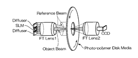
図10は、このような共通光路の利点を生かしたホログラム記録再生装置における光学系の概略図である(例えば、特許文献1参照。)。図10に示すように、光学系の中心付近には空間光変調器(SLM:Spatial Light Modulator)が配置され、2次元のデジタル画像に変換された記録情報がSLMに表示される。このSLMで光強度変調を受けた光が情報をもった物体光となる。 FIG. 10 is a schematic diagram of an optical system in a hologram recording / reproducing apparatus that takes advantage of such a common optical path (see, for example, Patent Document 1). As shown in FIG. 10, a spatial light modulator (SLM) is disposed near the center of the optical system, and the recording information converted into a two-dimensional digital image is displayed on the SLM. Light subjected to light intensity modulation by this SLM becomes object light having information.
この物体光の外側には参照光が配置されており、これら2つの光をホログラムメモリ媒体の中で重ね合わせることにより干渉縞を記録する。このとき、ホログラムメモリ媒体をわずかに回転させて位置をずらすことにより物体光からの情報をホログラムメモリ媒体に多重記録していく。再生時には、SLMから出射する光を完全に遮断し、参照光のみを記録された干渉縞に照射し、この干渉縞から再生された画像情報をCCDなどの2次元画像センサーにより受光して、情報を再生する。
上述のように、ホログラム記録では、ホログラムメモリ媒体上の同一箇所に多くの画像情報を多重記録することが可能であることから、ホログラムメモリ媒体の厚みを増やせば、原理的には、容量の上限はない。しかしながら、現実的には、様々な要因によりホログラムメモリ媒体の記録容量は制限され、中でも、レンズなどの光学素子やホログラムメモリ媒体から生じる散乱光が大きな問題になってくる。 As described above, in holographic recording, it is possible to multiplexly record a large amount of image information at the same location on the holographic memory medium. Therefore, if the thickness of the holographic memory medium is increased, the upper limit of the capacity is theoretically increased. There is no. However, in reality, the recording capacity of the hologram memory medium is limited due to various factors, and in particular, scattered light generated from an optical element such as a lens or the hologram memory medium becomes a serious problem.
一般的には、多重する画像の数(干渉縞の数)が増えると、個々の干渉縞から回折される再生光の回折効率が急激に低下してくる。その一方で、レンズなどの光学素子やホログラムメモリ媒体などに光が照射された場合、光学素子やホログラムメモリ媒体の表面荒さや材質の不均一性に起因して散乱光が発生する。こうした散乱光を皆無にすることは現実的には不可能であり、参照光から画像センサーの中に紛れ込んでくる散乱光が少なからず存在する。そして、このような光は光学的なノイズとして回折効率の小さい再生光の検出において妨げとなる。したがって、最終的に記録される容量の上限は再生光の光強度と散乱光の光強度の比(いわゆるS/N比)によって決定されることになる。 In general, as the number of images to be multiplexed (the number of interference fringes) increases, the diffraction efficiency of reproduced light diffracted from each interference fringe rapidly decreases. On the other hand, when light is irradiated onto an optical element such as a lens or a hologram memory medium, scattered light is generated due to the surface roughness of the optical element or the hologram memory medium and the nonuniformity of the material. In practice, it is impossible to eliminate such scattered light, and there is a considerable amount of scattered light that flows from the reference light into the image sensor. Such light is an optical noise that hinders the detection of reproduction light with low diffraction efficiency. Therefore, the upper limit of the capacity finally recorded is determined by the ratio of the light intensity of the reproduction light and the light intensity of the scattered light (so-called S / N ratio).
しかし、図10に示す光学系おいても、参照光と物体光が同じ光学系を伝搬するため、記録再生装置としては安定であり、しかも装置の小型化が期待できるが、共通光路であるがゆえに、上記の散乱光が画像センサーの中に入り込みやすいという問題点がある。したがって、これまでに図12に示すような共通光路型のホログラム記録再生光学系においては、記録容量の大容量化が達成されていない。 However, even in the optical system shown in FIG. 10, since the reference light and the object light propagate through the same optical system, it is stable as a recording / reproducing apparatus and can be expected to be downsized, but it is a common optical path. Therefore, there is a problem that the scattered light easily enters the image sensor. Therefore, in the common optical path type hologram recording / reproducing optical system as shown in FIG. 12, the recording capacity has not been increased so far.
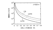
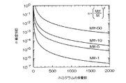
図8は、現行のCDと同じ記録面積をもつホログラムメモリ媒体を想定し、記録する情報の容量を0.2テラバイト、0.5テラバイト、1テラバイトとした場合について、対物レンズの開口数(NA)と多重するホログラム数の関係を計算したものである。一般的な対物レンズの開口数を0.5程度とすると、記録容量を0.2テラバイトとしたときの
ホログラム多重数は400程度、0.5テラバイトでは1000程度、1テラバイトでは2000程度であると予想される。
FIG. 8 shows a hologram memory medium having the same recording area as that of the current CD, and the numerical aperture (NA) of the objective lens when the capacity of information to be recorded is 0.2 terabyte, 0.5 terabyte, and 1 terabyte. ) And the number of multiplexed holograms. If the numerical aperture of a general objective lens is about 0.5, the number of multiplexed holograms when the recording capacity is 0.2 terabyte is about 400, about 1000 for 0.5 terabyte, and about 2000 for 1 terabyte. is expected.
一方で、回折効率ηは、記録材料の特性を示すMナンバー(M#)をホログラムの多重数Mで除したものの2乗に相当するが、例えば、図11に示したように、ホログラム記録材料の一般的なMナンバーをM#=5とすると、ホログラム多重数MがM=1000の場合、回折効率ηはη=2.5×10⁻⁵程度、ホログラム多重数MがM=2000の場合、回折効率ηはη=6.3×10⁻⁶程度と見積もられる。 On the other hand, the diffraction efficiency η corresponds to the square of the M number (M #) indicating the characteristics of the recording material divided by the number of multiplexed holograms M. For example, as shown in FIG. When M # = 5, the number of holograms M is M = 1000, the diffraction efficiency η is about η = 2.5 × 10 −5 , and the number of holograms M is M = 2000. The diffraction efficiency η is estimated to be about η = 6.3 × 10 −6 .
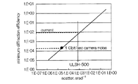
図7は、図10に示した従来のホログラムディスクストレージシステムにおいて測定された散乱光量とそれに対する回折効率ηの関係を示した図であるが、この図によれば、従来のシステムでは散乱光による制限により、最小の回折効率ηをη=1×10⁻²程度までしか下げることができず、前述したようなテラバイト相当の記録容量で要求されるη=1×10⁻⁵程度の小さい回折効率を検出することは不可能であった。 FIG. 7 is a diagram showing the relationship between the amount of scattered light measured in the conventional hologram disk storage system shown in FIG. 10 and the diffraction efficiency η corresponding thereto. According to this figure, the conventional system uses scattered light. Due to the limitation, the minimum diffraction efficiency η can be reduced only to about η = 1 × 10 −2 , and a small diffraction efficiency of about η = 1 × 10 −5 required for the recording capacity equivalent to the terabyte as described above. It was impossible to detect.
図10に示した従来の方式では、光学系の中心付近を物体光が占め、その周りを囲むように参照光が配置されており、参照光と物体光の分離は空間的に行なわれていたが、散乱光は文字通りあらゆる方向に伝播する成分を含んでいるため、このような空間的な分離だけですべての散乱光を取り除くことは非常に困難である。 In the conventional system shown in FIG. 10, the object light occupies the vicinity of the center of the optical system, and the reference light is arranged so as to surround the periphery, and the reference light and the object light are separated spatially. However, since the scattered light literally includes components that propagate in all directions, it is very difficult to remove all the scattered light only by such spatial separation.
そこで、本発明は、上述の問題点に鑑みてなされたものであって、参照光と物体光が同一光路上を伝播する光学系において、空間的な分離に加えて偏光を用いて散乱光ノイズの影響を極力低減しつつ、大容量化を実現可能なホログラムメモリ媒体および記録再生装置を提供することを目的とする。 Accordingly, the present invention has been made in view of the above-described problems, and in an optical system in which the reference light and the object light propagate on the same optical path, the scattered light noise is generated using polarized light in addition to spatial separation. An object of the present invention is to provide a hologram memory medium and a recording / reproducing apparatus capable of realizing a large capacity while reducing the influence of the above as much as possible.
請求項1に係る発明は、物体光と参照光とを照射して、該物体光の情報を干渉縞として記録する記録層と、該記録層を記録面側および該記録面に対向する側から挟むように配置され、入射光の偏光状態を変化させる第1および第2の位相差膜と、を有することを特徴とするホログラムメモリ媒体を提案している。
The invention according to
この発明によれば、記録層を挟んで配置された第1および第2の位相差膜により物体光と参照光の偏光状態が変化する。したがって、ホログラムメモリ媒体に入射するまでの物体光および参照光を異なる偏光状態とし、第2の位相差膜を2回透過させることにより、物体光の反射光と参照光を同一の偏光状態にして干渉縞を形成することができる。 According to the present invention, the polarization states of the object light and the reference light are changed by the first and second retardation films arranged with the recording layer interposed therebetween. Therefore, the object light and the reference light before entering the hologram memory medium are set to different polarization states, and the reflected light of the object light and the reference light are made to have the same polarization state by transmitting the second retardation film twice. Interference fringes can be formed.
請求項2に係る発明は、請求項1に記載されたホログラムメモリ媒体について、前記第2の位相差膜面に当接して設けられた反射層をさらに有することを特徴とするホログラムメモリ媒体を提案している。
この発明によれば、第2の位相差膜に当接して反射層を設けることにより、反射による偏光の変化を利用して物体光と参照光の偏光状態を記録層以外においては直交させ、記録層内のみ一致させることができるので、物体光と参照光を偏光により分離することができ、散乱光ノイズの影響を極力低減することができる。
The invention according to claim 2 proposes a hologram memory medium according to
According to the present invention, by providing the reflective layer in contact with the second retardation film, the polarization state of the object light and the reference light is made orthogonal except for the recording layer by utilizing the change in the polarization due to the reflection. Since only the layers can be matched, the object light and the reference light can be separated by polarization, and the influence of scattered light noise can be reduced as much as possible.
請求項3に係る発明は、請求項2に記載されたホログラムメモリ媒体について、前記反射層の前記第2の位相差膜面に対向する面に当接して設けられ、光を吸収するフィルター層をさらに有することを特徴とするホログラムメモリ媒体を提案している。
この発明によれば、反射層が一部の光を透過する半透明膜であった場合に、フィルター層が反射層を透過した光を吸収するため、不要な迷光の影響を極力低減することができる。
According to a third aspect of the invention, there is provided the hologram memory medium according to the second aspect, wherein a filter layer that is provided in contact with a surface of the reflective layer facing the second retardation film surface and absorbs light is provided. In addition, a holographic memory medium characterized by further comprising the above is proposed.
According to the present invention, when the reflective layer is a translucent film that transmits part of the light, the filter layer absorbs the light transmitted through the reflective layer, so that the influence of unnecessary stray light can be reduced as much as possible. it can.
請求項4に係る発明は、請求項1から請求項3のいずれかに記載されたホログラムメモリ媒体について、形状がディスク状であることを特徴とするホログラムメモリ媒体を提案している。
この発明によれば、形状をディスク状としたことから、従来の光ディスクに用いられる記録再生装置と同様な機構により、ホログラムメモリ媒体への情報の記録再生を行うことができる。
The invention according to claim 4 proposes a hologram memory medium characterized in that the shape of the hologram memory medium according to any one of
According to the present invention, since the shape is a disc shape, information can be recorded / reproduced to / from the hologram memory medium by a mechanism similar to that of a recording / reproducing apparatus used for a conventional optical disc.
請求項5に係る発明は、請求項1から請求項3のいずれかに記載されたホログラムメモリ媒体について、形状がカード状であることを特徴とするホログラムメモリ媒体を提案している。
この発明によれば、形状をカード状としたことから、ホログラムメモリ媒体を様々な分野に応用することができる。
The invention according to
According to the present invention, since the shape is a card shape, the hologram memory medium can be applied to various fields.
請求項6に係る発明は、請求項1から請求項3のいずれかに記載されたホログラムメモリ媒体について、形状がテープ状であることを特徴とするホログラムメモリ媒体を提案している。
この発明によれば、形状をテープ状としたことから、ホログラムメモリ媒体を様々な分野に応用することができる。
The invention according to
According to the present invention, since the shape is a tape, the hologram memory medium can be applied to various fields.
請求項7に係る発明は、前記請求項1から請求項6のいずれかに記載されたホログラムメモリ媒体に用いられる記録装置であって、前記物体光と参照光とが同一の光学系を伝搬するとともに、前記記録層の内部においてのみ、前記物体光と参照光の偏光状態が一致し、該記録層以外においては、前記物体光と参照光の偏光状態が直交していることを特徴とする記録装置を提案している。
The invention according to claim 7 is a recording apparatus used in the hologram memory medium according to any one of
請求項8に係る発明は、前記請求項1から請求項6のいずれかに記載されたホログラムメモリ媒体に用いられる再生装置であって、
再生光と参照光とが同一の光学系を伝搬するとともに、前記記録層以外においては、再生光と参照光の偏光状態が直交していることを特徴とする再生装置を提案している。
The invention according to claim 8 is a reproducing apparatus used for the hologram memory medium according to any one of
A reproduction apparatus is proposed in which the reproduction light and the reference light propagate through the same optical system, and the polarization states of the reproduction light and the reference light are orthogonal except for the recording layer.
これらの発明によれば、記録層以外の箇所では、物体光と参照光との偏光が直交した状態であり、参照光から発生する散乱光は参照光と同じ偏光であるため、この散乱光を検光子などの偏光分離素子により容易に除去することが可能である。 According to these inventions, the polarizations of the object light and the reference light are orthogonal to each other at the locations other than the recording layer, and the scattered light generated from the reference light is the same polarization as the reference light. It can be easily removed by a polarization separation element such as an analyzer.
本発明によれば、参照光と物体光が同一光路上を伝播する共通光路型の光学系において、最も問題となりやすい散乱光ノイズの影響を記録層以外の箇所では物体光と参照光との偏光を直交させ、また、不要な迷光を吸収する色フィルターを導入することにより極力低減することが可能となるという効果がある。
また、上記の構成とすることにより、光学系を簡素化しつつ、記録情報の大容量化を実現できるという効果がある。
According to the present invention, in the common optical path type optical system in which the reference light and the object light propagate on the same optical path, the influence of the scattered light noise which is most problematic is the polarization of the object light and the reference light at a place other than the recording layer By introducing a color filter that absorbs unnecessary stray light, it is possible to reduce as much as possible.
In addition, the above configuration has an effect that it is possible to increase the capacity of recorded information while simplifying the optical system.
以下、本発明の実施例に係るホログラムメモリ媒体および記録装置、再生装置について図1から図6を参照して詳細に説明する。 Hereinafter, a hologram memory medium, a recording apparatus, and a reproducing apparatus according to an embodiment of the present invention will be described in detail with reference to FIGS.
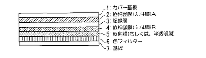
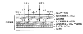
本発明の実施例に係るホログラムメモリ媒体は、図1に示すように、カバー層1と、位相差膜A(λ/4膜)2と、記録層3と、位相差膜B(λ/4膜)4と、反射層5と、色フィルター6と、基板7とから構成されている。なお、反射層5は光の一部を透過する半透明膜であってもよい。
As shown in FIG. 1, a hologram memory medium according to an embodiment of the present invention includes a
ここで、位相差膜A(λ/4膜)2および位相差膜B(λ/4膜)4は、例えば、左回り円偏光をS偏光に、右回り円偏光をP偏光に、S偏光を右回り円偏光に、P偏光を左回り円偏光に変換する。記録層3は、例えば、フォトポリマー等の感光材料により構成され、物体光と参照光とを同一箇所に照射することにより、物体光の情報を干渉縞として記録する。 Here, the retardation film A (λ / 4 film) 2 and the retardation film B (λ / 4 film) 4 are, for example, left-handed circularly polarized light as S-polarized light, right-handed circularly polarized light as P-polarized light, and S-polarized light. Is converted to clockwise circularly polarized light and P polarized light is converted to counterclockwise circularly polarized light. The recording layer 3 is made of, for example, a photosensitive material such as a photopolymer, and records object light information as interference fringes by irradiating the object light and the reference light at the same location.
色フィルター6は、反射層5を一部透過した光をすべて吸収する光学素子である。また、カバー層1は、ホログラムメモリ媒体内部を保護するための保護層であり、基板7は、ホログラムメモリ媒体のベースをなす部材である。
The
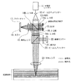
次に、図2を用いて、本発明の実施例に係る記録再生装置の光学系について説明する。
本発明の実施例に係る記録再生装置の光学系は、図2に示すように、光源である半導体レーザー11と、半導体レーザー11から射出されたレーザー光のビーム径を拡大するビームエキスパンダー12と、入射光を偏光するとともに、入射ビームを二つ、もしくはそれ以上の分離したビームに分割する偏光ビームスプリッター13と、入射光の偏光状態を変えるλ/4板14a、14b、14cと、物体光を生成する空間光変調器(SLM)15と、入射光を集光する集光レンズ16と、集光レンズ16の焦点位置に円形の孔部を有したアパーチャー17と、アパーチャー17を通過した光を反射するミラー18と、入射光の偏光状態を変えるλ/2板19と、入射光を二つ、もしくはそれ以上の分離したビームに分割するビームスプリッター20と、再生光と直交した光成分を取り除く検光子21と、再生光を受光する画像センサー22と、入射光を集光し、ホログラムメモリ媒体の記録層3に像を形成する対物レンズ23とから構成されている。なお、光源は、記録材料に感度のある波長に合ったレーザーであれば、半導体レーザーでなくてもよい。
Next, the optical system of the recording / reproducing apparatus according to the embodiment of the present invention will be described with reference to FIG.
As shown in FIG. 2, the optical system of the recording / reproducing apparatus according to the embodiment of the present invention includes a semiconductor laser 11 that is a light source, a beam expander 12 that expands a beam diameter of laser light emitted from the semiconductor laser 11, A polarization beam splitter 13 that polarizes incident light and splits the incident beam into two or more separated beams, λ / 4 plates 14a, 14b, and 14c that change the polarization state of incident light, and object light A spatial light modulator (SLM) 15 to be generated, a condensing lens 16 for condensing incident light, an aperture 17 having a circular hole at the focal position of the condensing lens 16, and light that has passed through the aperture 17 A reflecting mirror 18; a λ / 2 plate 19 that changes the polarization state of the incident light; and a beam splitter that divides the incident light into two or more separate beams. 20, an analyzer 21 that removes a light component orthogonal to the reproduction light, an image sensor 22 that receives the reproduction light, an objective lens 23 that collects the incident light and forms an image on the recording layer 3 of the hologram memory medium, and It is composed of The light source need not be a semiconductor laser as long as it is a laser that matches the wavelength sensitive to the recording material.
次に、図2から図6を用いて、ホログラムメモリ媒体に対する情報の記録、再生動作を説明する。
本実施例においては、ホログラムメモリ媒体への情報の記録、再生に用いられる半導体レーザー光11は直線偏光(S偏光)になっているものとする。半導体レーザー11から出射したレーザー光はビームエキスパンダー12により、そのビーム径が拡大され、偏光ビームスプリッター(PBS)13で反射して、λ/4板14aにおいて右回り円偏光に変換されたのち、空間光変調器(SLM)15に入射する。
Next, information recording and reproducing operations with respect to the hologram memory medium will be described with reference to FIGS.
In this embodiment, it is assumed that the semiconductor laser light 11 used for recording and reproducing information on the hologram memory medium is linearly polarized light (S-polarized light). The laser beam emitted from the semiconductor laser 11 is expanded in beam diameter by the beam expander 12, reflected by the polarization beam splitter (PBS) 13, and converted into clockwise circularly polarized light by the λ / 4 plate 14a, and then the space. The light enters the light modulator (SLM) 15.
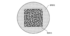
本実施例においては、図3に示すように、光学系の像面に物体光と参照光の両方が配置されている。なお、図3においては、一例として、物体光が光学系の中心を占め、その外側に参照光を配置しているが、例えば、物体光と参照光の位置関係が逆になっていても差し支えない。また、この図に示した物体光は長方形の内部を占めているが、例えば円形であってもなんら問題はない。 In this embodiment, as shown in FIG. 3, both object light and reference light are arranged on the image plane of the optical system. In FIG. 3, as an example, the object light occupies the center of the optical system, and the reference light is arranged outside the optical system. However, for example, the positional relationship between the object light and the reference light may be reversed. Absent. Further, although the object light shown in this figure occupies the inside of the rectangle, there is no problem even if it is circular, for example.
あらかじめ記録したい情報は決められた符号化の論理にしたがって2次元のデジタルデータに変換されており、この画像データがSLM15上に表示される。シフト多重で大きな多重度を実現するためには、参照光はランダムな位相変調や強度変調を受けたスペックルビームになっている必要があるが、図3の例では、SLM15の外側に拡散板を置き、この拡散板から発生するスペックルビームを参照光としている。
Information to be recorded in advance is converted into two-dimensional digital data according to a predetermined encoding logic, and this image data is displayed on the
このようなスペックルビームを発生させるには、他にも液晶を使った空間位相変調器や、ランダムフェーズプレートと呼ばれる特別に設計された光学素子を用いてもよい。また、物体光の表示に用いたSLM15と同一のSLM15を用い、物体光の外側にランダムなパターンを表示させて、この領域から発生するスペックルビームを参照光としてもよい。
In order to generate such a speckle beam, a spatial phase modulator using liquid crystal or a specially designed optical element called a random phase plate may be used. Alternatively, the
このように一つのSLM15上に物体光と参照光の両方を表示させ、かつ、SLM15として反射型の液晶ディスプレイを用いる場合には、SLM15自体にλ/4板としての機能が備わっているために、PBS13とSLM15との間に配置されているλ/4板14aは不要となる。なお、SLMとしてデジタルマイクロミラーデバイス(DMD)を用いる場合には、入射した光の偏光と直交させるために、このλ/4板が必要となる。
As described above, when both the object light and the reference light are displayed on one
いずれの方法であっても、物体光と参照光の像面から反射した光は、入射した偏光と直交したP偏光となり、PBS13を透過する。この透過した光は、別のλ/4板14bを透過し、集光レンズ16で集光される。このレンズの焦点位置には円形のアパーチャー17とミラー18とが配置されている。この焦点位置は、ホログラムメモリ媒体中における対物レンズ23の焦点位置と共役な位置関係になっている。なお、焦点位置におかれたアパーチャー17は、SLM15から発生した高次の回折光や散乱光などの不要な光を取り除くものであり、ホログラムの横方向サイズが必要以上に大きくなるのを防ぐ役割も果たしている。
In any method, the light reflected from the image planes of the object light and the reference light becomes P-polarized light orthogonal to the incident polarized light and passes through the
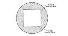
ミラーで反射した光はλ/4板14bを往復することになるため、偏光がP偏光からS偏光に変換され、再びPBS13において反射し、SLM15と共役な位置に再び像面を形成する。この像面位置には、図3示す参照光と物体光の配置を一例とすると、図4に示したような波長板が置かれており、参照光と物体光の偏光が互いに直交する。なお、図4においては、一例として物体光の領域にλ/2板を配置し、参照光の部分は単なるガラス基板になっているが、これらの位置関係は逆になってもなんら問題はない。
Since the light reflected by the mirror travels back and forth through the λ / 4
この波長板を透過した参照光と物体光は、その次に配置されたλ/4板14cを透過すると、物体光は例えば、左回り円偏光、参照光は右回り円偏光に変換される。さらに、物体光と参照光は、λ/4板14c、ビームスプリッター20を透過して、対物レンズ23によりホログラムメモリ媒体中に集光される。 When the reference light and the object light transmitted through the wavelength plate are transmitted through the λ / 4 plate 14c disposed next, the object light is converted into, for example, counterclockwise circularly polarized light, and the reference light is converted into clockwise circularly polarized light. Further, the object light and the reference light are transmitted through the λ / 4 plate 14 c and the beam splitter 20, and are collected in the hologram memory medium by the objective lens 23.
次に、図5に示したような偏光状態を例にとり、ホログラムメモリ媒体中に干渉縞を記録する様子を説明する。
ホログラムメモリ媒体に入射する物体光の偏光はλ/4板14cによって左回り円偏光(L)になっており、最初に透過する位相差膜A(λ/4膜)2によって、ホログラムメモリ媒体の記録層3ではS偏光となる。さらに、その下の位相差膜B(λ/4膜)4を透過すると、右回り円偏光(R)に変換される。
Next, taking a polarization state as shown in FIG. 5 as an example, a state in which interference fringes are recorded in the hologram memory medium will be described.
The polarization of the object light incident on the hologram memory medium is counterclockwise circularly polarized (L) by the λ / 4 plate 14c, and the retardation film A (λ / 4 film) 2 that is transmitted first causes the hologram memory medium to The recording layer 3 is S-polarized light. Further, when the light passes through the retardation film B (λ / 4 film) 4 thereunder, it is converted into clockwise circularly polarized light (R).
右回り円偏光(R)の物体光は、反射層5で反射されて左回り円偏光(L)になり、再び位相差膜B4を透過すると、今度は記録層3中で入射時とは直交したP偏光に変換される。一方、ホログラムメモリ媒体に入射する参照光は、物体光の偏光と直交した右回り円偏光(R)になっており、位相差膜A2を透過するとホログラムメモリ媒体中では、P偏光になる。したがって、反射層5で反射してきた物体光の偏光と一致するために、両者の光は互いに干渉し、その干渉縞(Holo−P)が記録層3を構成する記録材料中に記録される。
The clockwise circularly polarized light (R) is reflected by the reflecting
位相差膜A2および位相差膜B4の両方を透過した参照光は左回り円偏光(L)に変換される。この左回り円偏光(L)の参照光は反射層5で反射されると右回り円偏光(R)に回転方向が逆転し、再び位相差膜B4を透過すると記録層3の中ではS偏光に変換されている。この参照光は記録層3に入射する物体光の偏光と同じS偏光であり、両者は互いに干渉してホログラム(Holo−S)が記録される。色フィルター6は、反射層5が半透明膜であった場合に、一部透過した参照光や物体光をすべて吸収する。
The reference light transmitted through both the retardation film A2 and the retardation film B4 is converted into counterclockwise circularly polarized light (L). When the counterclockwise circularly polarized light (L) is reflected by the
次に、図6を用いて、再生時における偏光の様子について説明する。
再生時は、λ/4板14cの結晶軸を光軸中心に45度回転させて、結晶軸の向きがS偏光もしくはP偏光の偏光方向と平行になるように設定する。これにより、λ/4板14cは波長板として機能しなくなり、λ/4板14cを透過した光の偏光状態は変化しなくなる。この場合、図4に示した波長板を例にとると、記録媒体に入射する参照光の偏光はPBS13で反射したS偏光のままになっている。
再生時における参照光は偏光状態を除いて記録時のものと全く同じであり、この光がホログラムメモリ媒体中に書き込まれた干渉縞に照射されると、この干渉縞から記録時に書き込まれた物体光が回折現象により再生される。
Next, the state of polarized light during reproduction will be described with reference to FIG.
At the time of reproduction, the crystal axis of the λ / 4 plate 14c is rotated by 45 degrees about the optical axis so that the direction of the crystal axis is parallel to the polarization direction of S-polarized light or P-polarized light. As a result, the λ / 4 plate 14c does not function as a wavelength plate, and the polarization state of the light transmitted through the λ / 4 plate 14c does not change. In this case, taking the wavelength plate shown in FIG. 4 as an example, the polarization of the reference light incident on the recording medium remains the S-polarized light reflected by the
The reference light at the time of reproduction is exactly the same as that at the time of recording except for the polarization state. When this light is irradiated to the interference fringe written in the hologram memory medium, the object written at the time of recording from the interference fringe Light is regenerated by the diffraction phenomenon.
S偏光の参照光は位相差膜A2を透過すると左回り円偏光(L)に変換され、ホログラム(Holo−P)に入射する。ホログラム(Holo−P)は、対向する物体光と参照光により書き込まれた反射型のホログラムであり、再生は参照光の一部が反射することによって行われる。したがって、左回り円偏光(L)の参照光から再生された再生光の偏光は反射によって回転方向が逆転して右回り円偏光(R)になっており、位相差膜A2を透過した再生光は記録媒体の外で参照光の偏光とは直交したP偏光になっている。 When the S-polarized reference light passes through the retardation film A2, it is converted into counterclockwise circularly polarized light (L) and enters the hologram (Holo-P). A hologram (Holo-P) is a reflection type hologram written by opposed object light and reference light, and reproduction is performed by reflecting a part of the reference light. Therefore, the polarization of the reproduction light regenerated from the counterclockwise circularly polarized light (L) is reversed to the rotation direction by reflection and becomes right-handed circularly polarized light (R), and the reproduced light transmitted through the retardation film A2. Is P-polarized light perpendicular to the polarization of the reference light outside the recording medium.
ホログラム(Holo−P)を透過した参照光は位相差膜B4を透過するとP偏光になり、反射層5で反射するが、直線偏光の光は鏡面反射によって偏光が変化しないので、再び位相差膜B4を透過すると、記録層3内では再び左回り円偏光(L)に戻る。この参照光はホログラム(Holo−S)に入射するが、ホログラム(Holo−S)もやはり対向する物体光と参照光で記録された反射型のホログラムであり、左回り円偏光(L)の参照光により再生された再生光の偏光は回転方向が逆転した右回り円偏光(R)である。
When the reference light transmitted through the hologram (Holo-P) is transmitted through the retardation film B4, it becomes P-polarized light and is reflected by the
ホログラム(Holo−S)から再生された右回り円偏光(R)の再生光は、位相差膜B4を透過してS偏光になり、反射層5で反射するが、鏡面反射において直線偏光の偏光状態は変化しないので、再び位相差膜B4を透過すると右回り円偏光(R)に戻っている。次に、位相差膜A2を透過すると、結果としてホログラム(Holo−S)からの再生光は記録媒体の外でP偏光になる。すなわち、ホログラム(Holo−P)およびホログラム(Holo−S)からの再生光はいずれも記録媒体の外では参照光の偏光とは直交したP偏光になっている。
The right-handed circularly polarized light (R) reproduced light reproduced from the hologram (Holo-S) is transmitted through the retardation film B4 to become S-polarized light and reflected by the
この再生光は、図2に示した光学系を入射時とは逆側に戻っていき、対物レンズ23を透過した後、ビームスプリッター20で反射して、この再生光の偏光成分のみを透過する検光子21を通過してCCDなどの画像センサー22で受光される。 The reproduction light returns to the side opposite to the incident time in the optical system shown in FIG. 2, and after passing through the objective lens 23, is reflected by the beam splitter 20 and transmits only the polarization component of the reproduction light. The light passes through the analyzer 21 and is received by an image sensor 22 such as a CCD.
再生光に変換されなかった参照光は、偏光状態が再生光の偏光と直交しており、検光子21を透過できずにカットされる。また、参照光から発生した記録媒体の表面反射成分も再生光の偏光と直交したままであり、この光も画像センサー22の前に置かれた検光子21により取り除かれる。 The reference light that has not been converted to the reproduction light has a polarization state orthogonal to the polarization of the reproduction light, and is not transmitted through the analyzer 21 but is cut. Further, the surface reflection component of the recording medium generated from the reference light also remains orthogonal to the polarization of the reproduction light, and this light is also removed by the analyzer 21 placed in front of the image sensor 22.
以上、本実施例によれば、参照光と物体光が同一光路上を伝播する共通光路型の光学系を採用しつつ、光学系に空間分離と偏光分離とを用い、さらに、不要な迷光を吸収する色フィルターを導入したことから、散乱光ノイズの影響を極力低減することができる。 As described above, according to the present embodiment, while adopting a common optical path type optical system in which the reference light and the object light propagate on the same optical path, spatial separation and polarization separation are used in the optical system, and unnecessary stray light is further generated. Since an absorbing color filter is introduced, the influence of scattered light noise can be reduced as much as possible.
以上、図面を参照して本発明の実施例について詳述してきたが、具体的な構成はこれらの実施形態に限られるものではなく、この発明の要旨を逸脱しない範囲の設計変更等も含まれる。 The embodiments of the present invention have been described in detail with reference to the drawings. However, the specific configuration is not limited to these embodiments, and includes design changes and the like without departing from the scope of the present invention. .
1・・・カバー層、2・・・位相差膜A(λ/4膜)、3・・・記録層、4・・・位相差膜B(λ/4膜)、5・・・反射膜、6・・・色フィルター、7・・・基板、11・・・半導体レーザー、12・・・ビームエキスパンダー、13・・・偏光ビームスプリッター、14a、14b、14c・・・λ/4板、15・・・空間光変調器(SLM)、16・・・集光レンズ、17・・・アパーチャー、18・・・ミラー、19・・・λ/2板、20・・・ビームスプリッター、21・・・検光子、22・・・画像センサー、23・・・対物レンズ、
DESCRIPTION OF
Claims (8)
該記録層を記録面側および該記録面に対向する側から挟むように配置され、入射光の偏光状態を変化させる第1および第2の位相差膜と、
を有することを特徴とするホログラムメモリ媒体。 A recording layer that irradiates object light and reference light and records information of the object light as interference fringes;
First and second retardation films arranged to sandwich the recording layer from the recording surface side and the side facing the recording surface, and changing the polarization state of incident light;
A holographic memory medium comprising:
前記物体光と参照光とが同一の光学系を伝搬するとともに、前記記録層の内部においてのみ、前記物体光と参照光の偏光状態が一致し、該記録層以外においては、前記物体光と参照光の偏光状態が直交していることを特徴とする記録装置。 A recording device used for the hologram memory medium according to any one of claims 1 to 6,
The object light and the reference light propagate through the same optical system, and the polarization states of the object light and the reference light match only inside the recording layer, and the object light and the reference other than the recording layer. A recording apparatus characterized in that the polarization state of light is orthogonal.
再生光と参照光とが同一の光学系を伝搬するとともに、前記記録層以外においては、再生光と参照光の偏光状態が直交していることを特徴とする再生装置。
A reproducing apparatus used for the hologram memory medium according to any one of claims 1 to 6,
A reproduction apparatus characterized in that the reproduction light and the reference light propagate through the same optical system, and the polarization states of the reproduction light and the reference light are orthogonal except for the recording layer.
Priority Applications (5)
| Application Number | Priority Date | Filing Date | Title |
|---|---|---|---|
| JP2004262932A JP2005292765A (en) | 2004-03-09 | 2004-09-09 | Hologram memory medium, recording apparatus, and reproducing apparatus |
| EP05726931A EP1723641A4 (en) | 2004-03-09 | 2005-03-07 | HOLOGRAM MEASUREMENT MEDIUM AND RECORDING DEVICE AND PLAYING DEVICE THEREFOR |
| PCT/KR2005/000633 WO2005086144A1 (en) | 2004-03-09 | 2005-03-07 | Hologram recording medium, and recording apparatus and reproducing apparatus for the same |
| US11/072,393 US7369286B2 (en) | 2004-03-09 | 2005-03-07 | Hologram recording medium, and recording apparatus and reproducing apparatus for the same |
| TW094107091A TWI265496B (en) | 2004-03-09 | 2005-03-09 | Hologram recording medium, and recording apparatus and reproducing apparatus for the same |
Applications Claiming Priority (2)
| Application Number | Priority Date | Filing Date | Title |
|---|---|---|---|
| JP2004065842 | 2004-03-09 | ||
| JP2004262932A JP2005292765A (en) | 2004-03-09 | 2004-09-09 | Hologram memory medium, recording apparatus, and reproducing apparatus |
Publications (1)
| Publication Number | Publication Date |
|---|---|
| JP2005292765A true JP2005292765A (en) | 2005-10-20 |
Family
ID=34921737
Family Applications (1)
| Application Number | Title | Priority Date | Filing Date |
|---|---|---|---|
| JP2004262932A Pending JP2005292765A (en) | 2004-03-09 | 2004-09-09 | Hologram memory medium, recording apparatus, and reproducing apparatus |
Country Status (5)
| Country | Link |
|---|---|
| US (1) | US7369286B2 (en) |
| EP (1) | EP1723641A4 (en) |
| JP (1) | JP2005292765A (en) |
| TW (1) | TWI265496B (en) |
| WO (1) | WO2005086144A1 (en) |
Cited By (3)
| Publication number | Priority date | Publication date | Assignee | Title |
|---|---|---|---|---|
| EP1916653A1 (en) | 2006-10-25 | 2008-04-30 | Funai Electric Co., Ltd. | Holographic information recording and reproducing apparatus |
| JP2008269771A (en) * | 2007-04-19 | 2008-11-06 | Thomson Licensing | Apparatus for reading from and / or writing to holographic storage media |
| JP5278334B2 (en) * | 2008-01-10 | 2013-09-04 | 日本電気株式会社 | Optical information recording / reproducing apparatus, optical head apparatus, and optical information recording / reproducing method |
Families Citing this family (15)
| Publication number | Priority date | Publication date | Assignee | Title |
|---|---|---|---|---|
| US7088482B2 (en) * | 2004-02-10 | 2006-08-08 | Imation Corp. | Holographic recording techniques using first and second portions of a spatial light modulator |
| US7088481B2 (en) * | 2004-02-10 | 2006-08-08 | Imation Corp. | Holographic recording techniques using reference zone of spatial light modulator |
| US7283286B2 (en) * | 2004-12-27 | 2007-10-16 | Sony Corporation | Hologram recording/reproducing device and optical unit |
| JPWO2006080061A1 (en) * | 2005-01-27 | 2008-06-19 | 富士通株式会社 | Hologram recording device |
| WO2007000801A1 (en) * | 2005-06-27 | 2007-01-04 | Fujitsu Limited | Optical information recording/reproducing device |
| US20070030787A1 (en) * | 2005-08-05 | 2007-02-08 | Samsung Electronics Co., Ltd. | Data read/write device for holographic storage medium and method thereof |
| TW200801865A (en) * | 2006-03-29 | 2008-01-01 | Koninkl Philips Electronics Nv | Setup for storing data in a holographic storage medium and phase plate |
| TWI330837B (en) * | 2007-02-14 | 2010-09-21 | Ind Tech Res Inst | System for recording and reproducing holographic storage which has tracking servo projection |
| WO2009022788A1 (en) * | 2007-08-13 | 2009-02-19 | Samsung Electronics Co., Ltd. | Holographic information storage medium, and method and apparatus for recording/reproducing holographic information using the same |
| KR101439846B1 (en) * | 2007-12-12 | 2014-09-12 | 삼성전자주식회사 | Holographic data storage medium, and apparatus and method for recording/reproducing holographic data on/from the same |
| TWI384477B (en) * | 2008-09-03 | 2013-02-01 | 財團法人工業技術研究院 | Reusable data storage medium |
| EP2337026A1 (en) * | 2009-12-18 | 2011-06-22 | Thomson Licensing | Optical recording medium and apparatus and method for reading from the medium |
| TWI475253B (en) * | 2012-05-04 | 2015-03-01 | Univ Nat Chiao Tung | Miniature microscope and manufacturing method of holographic optical element thereof |
| CN105023589B (en) * | 2015-07-27 | 2018-02-02 | 青岛泰谷光电工程技术有限公司 | Leaded light component applied to multi-level full figure stocking mechanism |
| US20180307047A1 (en) * | 2017-04-19 | 2018-10-25 | Thalmic Labs Inc. | Systems, devices, and methods for holographic optical elements |
Citations (4)
| Publication number | Priority date | Publication date | Assignee | Title |
|---|---|---|---|---|
| JPH05101398A (en) * | 1991-10-11 | 1993-04-23 | Hitachi Ltd | Three-dimensional recording / reproducing device |
| JPH07230243A (en) * | 1994-02-18 | 1995-08-29 | Nippondenso Co Ltd | Production of hologram |
| JP2004311001A (en) * | 2003-03-24 | 2004-11-04 | Fuji Xerox Co Ltd | Optical recording device and optical recording/ reproducing device |
| JP2005174401A (en) * | 2003-12-09 | 2005-06-30 | Pioneer Electronic Corp | Hologram recording medium and recording and reproducing system |
Family Cites Families (7)
| Publication number | Priority date | Publication date | Assignee | Title |
|---|---|---|---|---|
| JP3452113B2 (en) * | 1996-08-30 | 2003-09-29 | ソニー株式会社 | Optical information recording apparatus and method, optical information reproducing apparatus and method, and optical information recording medium |
| DE69941481D1 (en) * | 1998-02-27 | 2009-11-12 | Optware Corp | METHOD AND DEVICE FOR OPTICAL INFORMATION, METHOD AND DEVICE FOR REPRODUCING OPTICAL INFORMATION, RECORDING DEVICE, PLAYING OPTICAL INFORMATION AND OPTICAL INFORMATION RECORDING MEDIUM |
| US6108110A (en) | 1999-02-25 | 2000-08-22 | Siros Technologies, Inc. | Optical relay for pixel-based holographic storage and retrieval |
| JP3639202B2 (en) | 2000-07-05 | 2005-04-20 | 株式会社オプトウエア | Optical information recording apparatus and method, optical information reproducing apparatus and method, and optical information recording and reproducing apparatus and method |
| JP3655819B2 (en) | 2000-08-07 | 2005-06-02 | 株式会社オプトウエア | Optical information recording apparatus and method, optical information reproducing apparatus and method, and optical information recording and reproducing apparatus and method |
| US6721076B2 (en) * | 2001-08-03 | 2004-04-13 | Inphase Technologies, Inc. | System and method for reflective holographic storage with associated multiplexing techniques |
| JP4156911B2 (en) * | 2002-12-02 | 2008-09-24 | 新オプトウエア株式会社 | Optical information recording medium, optical information recording apparatus, and optical information reproducing apparatus |
-
2004
- 2004-09-09 JP JP2004262932A patent/JP2005292765A/en active Pending
-
2005
- 2005-03-07 US US11/072,393 patent/US7369286B2/en not_active Expired - Fee Related
- 2005-03-07 WO PCT/KR2005/000633 patent/WO2005086144A1/en not_active Ceased
- 2005-03-07 EP EP05726931A patent/EP1723641A4/en not_active Withdrawn
- 2005-03-09 TW TW094107091A patent/TWI265496B/en not_active IP Right Cessation
Patent Citations (4)
| Publication number | Priority date | Publication date | Assignee | Title |
|---|---|---|---|---|
| JPH05101398A (en) * | 1991-10-11 | 1993-04-23 | Hitachi Ltd | Three-dimensional recording / reproducing device |
| JPH07230243A (en) * | 1994-02-18 | 1995-08-29 | Nippondenso Co Ltd | Production of hologram |
| JP2004311001A (en) * | 2003-03-24 | 2004-11-04 | Fuji Xerox Co Ltd | Optical recording device and optical recording/ reproducing device |
| JP2005174401A (en) * | 2003-12-09 | 2005-06-30 | Pioneer Electronic Corp | Hologram recording medium and recording and reproducing system |
Cited By (4)
| Publication number | Priority date | Publication date | Assignee | Title |
|---|---|---|---|---|
| EP1916653A1 (en) | 2006-10-25 | 2008-04-30 | Funai Electric Co., Ltd. | Holographic information recording and reproducing apparatus |
| JP2008269771A (en) * | 2007-04-19 | 2008-11-06 | Thomson Licensing | Apparatus for reading from and / or writing to holographic storage media |
| US8284469B2 (en) | 2007-04-19 | 2012-10-09 | Thomson Licensing | Apparatus for reading from and/or writing to holographic storage media |
| JP5278334B2 (en) * | 2008-01-10 | 2013-09-04 | 日本電気株式会社 | Optical information recording / reproducing apparatus, optical head apparatus, and optical information recording / reproducing method |
Also Published As
| Publication number | Publication date |
|---|---|
| TWI265496B (en) | 2006-11-01 |
| WO2005086144A1 (en) | 2005-09-15 |
| US20050200928A1 (en) | 2005-09-15 |
| TW200531050A (en) | 2005-09-16 |
| EP1723641A1 (en) | 2006-11-22 |
| EP1723641A4 (en) | 2009-03-04 |
| US7369286B2 (en) | 2008-05-06 |
Similar Documents
| Publication | Publication Date | Title |
|---|---|---|
| JP3924549B2 (en) | Hologram recording / reproducing method and apparatus | |
| JP4991872B2 (en) | Configuration of monocular holographic data storage system | |
| JP2005292765A (en) | Hologram memory medium, recording apparatus, and reproducing apparatus | |
| JP4778924B2 (en) | Optical information processing apparatus and optical information processing method | |
| JP2004185707A (en) | Optical information recording medium, optical information recording apparatus and optical information reproducing apparatus having the optical information recording medium, and method of manufacturing polarization changing layer | |
| JP4289921B2 (en) | Holographic recording apparatus and reproducing apparatus | |
| JP2006189597A (en) | Hologram recording / reproducing apparatus and hologram recording / reproducing method | |
| JP4355607B2 (en) | Holographic recording method, holographic recording apparatus, holographic recording / reproducing method, holographic recording / reproducing apparatus, and holographic recording medium | |
| JP4162511B2 (en) | Hologram recording / reproducing method and hologram recording medium | |
| JP2005148700A (en) | Holographic recording apparatus, holographic reconstructing apparatus, and mask | |
| JP4108571B2 (en) | Holographic ROM system | |
| JP4610976B2 (en) | Hologram memory medium, recording apparatus, and reproducing apparatus | |
| JP4474513B2 (en) | Optical information reproducing apparatus and optical information storage / reproducing apparatus | |
| KR100619052B1 (en) | Hologram memory medium, recording apparatus therefor, and reproducing apparatus therefor | |
| JP2016219088A (en) | Method and device for holographic recording and reproducing | |
| JP4748043B2 (en) | Optical recording apparatus, optical recording method, recording medium, and reproducing method | |
| JP2004171611A (en) | Optical information recording device and optical information reproducing device | |
| JP2007149253A (en) | Optical pickup device for holography | |
| JP2008091014A (en) | Small apparatus for reproducing and / or recording holographic recording media | |
| JP2006259519A (en) | Hologram recording device | |
| JP4669927B2 (en) | Optical information recording method and optical information reproducing method | |
| JP2005215381A (en) | Hologram recording carrier, and hologram recording and reproducing method and apparatus | |
| JP2005025906A (en) | Device and method for recording/reproducing optical information | |
| JP4349167B2 (en) | Hologram recording apparatus, hologram reproducing apparatus, hologram recording method, and hologram reproducing method | |
| JP5298267B2 (en) | Optical information reproducing apparatus and reproducing method |
Legal Events
| Date | Code | Title | Description |
|---|---|---|---|
| A621 | Written request for application examination |
Free format text: JAPANESE INTERMEDIATE CODE: A621 Effective date: 20070307 |
|
| A131 | Notification of reasons for refusal |
Free format text: JAPANESE INTERMEDIATE CODE: A131 Effective date: 20100202 |
|
| A02 | Decision of refusal |
Free format text: JAPANESE INTERMEDIATE CODE: A02 Effective date: 20100629 |