JP2005292670A - Light guide and endoscope - Google Patents
Light guide and endoscope Download PDFInfo
- Publication number
- JP2005292670A JP2005292670A JP2004110449A JP2004110449A JP2005292670A JP 2005292670 A JP2005292670 A JP 2005292670A JP 2004110449 A JP2004110449 A JP 2004110449A JP 2004110449 A JP2004110449 A JP 2004110449A JP 2005292670 A JP2005292670 A JP 2005292670A
- Authority
- JP
- Japan
- Prior art keywords
- optical fiber
- light guide
- fiber bundle
- light
- fibers
- Prior art date
- Legal status (The legal status is an assumption and is not a legal conclusion. Google has not performed a legal analysis and makes no representation as to the accuracy of the status listed.)
- Withdrawn
Links
Images

Landscapes
- Instruments For Viewing The Inside Of Hollow Bodies (AREA)
- Optical Fibers, Optical Fiber Cores, And Optical Fiber Bundles (AREA)
- Endoscopes (AREA)
Abstract
【課題】広い照射領域を持ちつつその照射領域の中央部における強度の落ち込みを防止できるライトガイド,及び、このようなライトガイドが組み込まれた内視鏡を、提供する。
【解決手段】軟性内視鏡10内に組み込まれたライトガイド100は、束ねられた多数の石英ファイバからなる第1光ファイバ束101と、束ねられつつ縒られた多数の多成分ファイバからなる第2光ファイバ束102とを、備えている。また、第2光ファイバ束102は、第1光ファイバ束101を中心としてこの第1光ファイバ束101の周囲に多数配置されている。
【選択図】図4A light guide capable of preventing a drop in intensity at the center of the irradiation region while having a wide irradiation region, and an endoscope incorporating such a light guide are provided.
A light guide 100 incorporated in a flexible endoscope 10 includes a first optical fiber bundle 101 made up of many bundled quartz fibers and a multiplicity of multicomponent fibers made up of bundles. 2 optical fiber bundles 102. A large number of second optical fiber bundles 102 are arranged around the first optical fiber bundle 101 with the first optical fiber bundle 101 as the center.
[Selection] Figure 4
Description
本発明は、内視鏡の挿入部の先端が挿入された体腔内に光を導くためのライトガイドと、このようなライトガイドが組み込まれた内視鏡とに、関する。 The present invention relates to a light guide for guiding light into a body cavity into which a distal end of an insertion portion of an endoscope is inserted, and an endoscope in which such a light guide is incorporated.
周知のように、生体組織は、可視帯域中の短波長側の光や紫外領域の光が照射されると、励起して蛍光を発する。また、腫瘍や癌などの病変が生じている異常な生体組織は、正常な生体組織よりも弱い蛍光を発する。この反応現象は、体腔壁下の生体組織によっても引き起こされ得る。近年、この反応現象を利用することによって体腔壁下の生体組織に生じた異状を観察するための内視鏡システムが、開発されている。 As is well known, biological tissue is excited and emits fluorescence when irradiated with light on the short wavelength side in the visible band or light in the ultraviolet region. In addition, an abnormal living tissue in which a lesion such as a tumor or cancer has occurred emits weaker fluorescence than a normal living tissue. This reaction phenomenon can also be caused by living tissue below the body cavity wall. In recent years, endoscope systems have been developed for observing abnormalities generated in living tissue under the body cavity wall by utilizing this reaction phenomenon.
ところで、医療用の内視鏡の挿入部の先端は、光が届かない生体の体腔の中に挿入される。そのため、多くの内視鏡には、その先端が挿入された体腔内を照明するための光を導くライトガイドが、組み込まれている。また、内視鏡の挿入部が軟性タイプである場合、ライトガイドには、可撓性のある光ファイバが採用されている。 By the way, the distal end of the insertion portion of the medical endoscope is inserted into a body cavity of a living body where light does not reach. Therefore, many endoscopes incorporate a light guide that guides light for illuminating the body cavity into which the distal end is inserted. Further, when the insertion portion of the endoscope is a soft type, a flexible optical fiber is employed for the light guide.
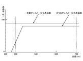
光ファイバには、コア及びクラッドの両方が多成分ガラスにて製造された多成分ファイバや、少なくともコアが石英ガラスにて製造された石英ファイバがある。石英ファイバは、多成分ファイバに比べると、許容される最小曲げ半径は小さくないものの、図5の分光透過率のグラフに示されるように、高い透過率を有し、特に、可視帯域中の短波長側の光や紫外領域の光に対して高い透過率を有している。つまり、石英ファイバは、多成分ファイバに比べると、体腔壁下の生体組織を励起させるための励起光を効率よく導くことができる。 Optical fibers include multi-component fibers in which both the core and the clad are made of multi-component glass, and quartz fibers in which at least the core is made of quartz glass. Quartz fiber has a high transmittance as shown in the spectral transmittance graph of FIG. It has a high transmittance for light on the wavelength side and light in the ultraviolet region. That is, the quartz fiber can efficiently guide the excitation light for exciting the living tissue under the body cavity wall, compared to the multicomponent fiber.
そして、このような石英ファイバを束ねたものがライトガイドとして内視鏡内に組み込まれた内視鏡システムが、特許文献1に開示されている。
前述した特許文献1記載のライトガイドは、石英ファイバからなるため、多成分ファイバからなるものよりも高強度な励起光を、体腔内に照射することができる。 Since the light guide described in Patent Document 1 described above is made of a quartz fiber, it can irradiate a body cavity with excitation light having a higher intensity than that of a multi-component fiber.
しかしながら、石英ファイバの開口数は、多成分ファイバよりも小さいため、ライトガイドに石英ファイバを採用すると、照射領域が狭くなるという問題があった。 However, since the numerical aperture of the quartz fiber is smaller than that of the multi-component fiber, there is a problem that the irradiation area becomes narrow when the quartz fiber is used for the light guide.
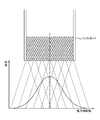
一方、光ファイバの材料の違いに拘わらず必ず生じてしまう現象として、図6の説明図に示されるように、束ねられた光ファイバの先端から射出された光の強度が、照射範囲の中央部分において落ち込むというものがある。このような照射ムラの原因となる現象が生じないようにするため、最近では、束ねられた光ファイバを縒ったものが、ライトガイドに採用されつつある。図7は、束ねられつつ縒られた多成分ファイバのみからなる従来のライトガイドから励起光が射出されたときの照射範囲と強度分布とを示す説明図である。 On the other hand, as shown in the explanatory diagram of FIG. 6, as a phenomenon that always occurs regardless of the difference in the material of the optical fiber, the intensity of the light emitted from the tip of the bundled optical fiber is the central portion of the irradiation range. There is something to be depressed. In order to prevent such a phenomenon that causes uneven irradiation, a bundle of bundled optical fibers has recently been adopted for a light guide. FIG. 7 is an explanatory diagram showing an irradiation range and an intensity distribution when excitation light is emitted from a conventional light guide made of only multi-component fibers that are twisted while being bundled.
ところが、束ねられた多成分ファイバに縒りを施しても、ライトガイドを湾曲させたときに問題が生じないが、束ねられた石英ファイバに縒りを施すと、多成分ファイバに比べて石英ファイバが硬いことから、ライトガイドを湾曲させたときに、その中の石英ファイバが折れてしまうことがあった。このため、束ねられた石英ファイバには、縒りを施すことができないので、束ねられた石英ファイバをライトガイドに採用すると、照射範囲の中央部分における強度の落ち込みが防げないという問題があった。 However, even if the bundled multicomponent fiber is twisted, there is no problem when the light guide is bent. However, if the bundled quartz fiber is twisted, the quartz fiber is harder than the multicomponent fiber. For this reason, when the light guide is bent, the quartz fiber therein may break. For this reason, since the bundled quartz fibers cannot be twisted, there is a problem that if the bundled quartz fibers are used for the light guide, a drop in strength cannot be prevented in the central portion of the irradiation range.
本発明は、前述したような従来の問題点に鑑みてなされたものであり、その課題は、高強度の励起光を導光できるにも拘わらず、広い照射領域を持ち、且つ、その照射領域の中央部における強度の落ち込みを防止できるライトガイドを、提供することにある。また、本発明の課題は、このようなライトガイドが組み込まれた内視鏡を、提供することにある。 The present invention has been made in view of the conventional problems as described above, and the problem is that although the high intensity excitation light can be guided, it has a wide irradiation area and the irradiation area. It is in providing the light guide which can prevent the fall of the intensity | strength in the center part. Moreover, the subject of this invention is providing the endoscope incorporating such a light guide.
上記の課題を解決するために発明されたライトガイド,及び、上記の課題を解決するために発明された内視鏡に組み込まれているライトガイドは、以下に記述するように、構成されている。 The light guide invented to solve the above problem and the light guide incorporated in the endoscope invented to solve the above problem are configured as described below. .
すなわち、このライトガイドは、束ねられた多数の石英ファイバからなる第1光ファイバ束と、前記第1光ファイバ束を中心としてこの第1光ファイバ束の周囲に配置された多数の多成分ファイバとを備え、前記各多成分ファイバが縒られていることを、特徴としている。 That is, the light guide includes a first optical fiber bundle made of a large number of bundled quartz fibers, and a multiplicity of multicomponent fibers arranged around the first optical fiber bundle with the first optical fiber bundle as a center. And each of the multicomponent fibers is wound.
このように、束ねられた石英ファイバからなる第1光ファイバ束をライトガイド内の中心に位置させることにより、石英ファイバの開口数の小ささや透過率の高さを利用して、照射領域の中央部分の強度を高くすることができ、特に、可視帯域中の短波長側の光や紫外領域の光を導く場合に、照射領域の中央部分の強度を高くすることができる。然も、石英ファイバは縒られていないため、ライトガイド全体を湾曲させても、石英ファイバが折れる心配がない。 In this way, by positioning the first optical fiber bundle made of the bundled quartz fibers in the center of the light guide, the center of the irradiation region can be obtained by utilizing the small numerical aperture and the high transmittance of the quartz fiber. The intensity of the portion can be increased. Particularly, when the light on the short wavelength side in the visible band or the light in the ultraviolet region is guided, the intensity of the central portion of the irradiation region can be increased. However, since the quartz fiber is not beaten, there is no fear of the quartz fiber breaking even if the entire light guide is curved.
また、縒られた多成分ファイバをライトガイド内の周縁に位置させることにより、照射領域を拡大することができる。多成分ファイバは、可視帯域中の短波長側の光や紫外領域の光については、多少の透過率を有している。このため、可視帯域中の短波長側の光や紫外領域の光を導く場合においては、本発明のライトガイドによる照射領域の周縁部分の強度は、石英ファイバからなる従来のライトガイドに比べて、多少落ちるものの、その周縁部分を確実に拡大することができる。 Further, the irradiation region can be enlarged by positioning the beaten multi-component fiber at the periphery in the light guide. The multicomponent fiber has some transmittance for light on the short wavelength side in the visible band and light in the ultraviolet region. For this reason, when guiding light on the short wavelength side in the visible band and light in the ultraviolet region, the intensity of the peripheral portion of the irradiation region by the light guide of the present invention is higher than that of a conventional light guide made of quartz fiber. Although it falls a little, the peripheral part can be expanded reliably.
以上に説明したように、本発明によれば、高強度の励起光を導光できるにも拘わらず、広い照射領域を持ち、且つ、その照射領域の中央部における強度の落ち込みを防止することができるようになる。 As described above, according to the present invention, although it is possible to guide high-intensity excitation light, it has a wide irradiation area and can prevent a drop in intensity at the center of the irradiation area. become able to.
以下、添付図面に基づいて、本発明を実施するための形態を、説明する。 DESCRIPTION OF EMBODIMENTS Hereinafter, embodiments for carrying out the present invention will be described with reference to the accompanying drawings.
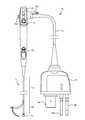
図1は、本発明の実施形態である軟性内視鏡10の外観図である。本実施形態の軟性内視鏡10は、体腔内に挿入するために細長く形成された挿入部11と、アングルノブ12aや各種のボタン12bが設けられた操作部12と、この操作部12の側面から延びたケーブル部13と、このケーブル部13の先端を図示せぬプロセッサ装置に接続するためコネクタ部14とを、備えている。
FIG. 1 is an external view of a
挿入部11は、外皮としての樹脂製の被覆管に覆われた管状の内部骨格構造を、有しており、その内部骨格構造は、基端側の大部分を占める軟性部11aと、この軟性部11aの先端側に位置する湾曲部11bと、その先端に位置する先端部11cとに、区分される。
The insertion portion 11 has a tubular inner skeleton structure covered with a resin-made cladding tube as an outer skin, and the inner skeleton structure includes a
軟性部11aは、長尺な平板状の金属板を螺旋状に巻くことによって形成された丸管や、その丸管を覆う金属編管により、構成されている。このような構成により、軟性部11aは、与えられた外力に応じて柔軟に屈曲するとともに、体腔壁を傷付けない程度に屈曲の状態を維持できる剛性を保有し得る。
The
湾曲部11bは、いわゆる節輪を複数連結することによって湾曲可能な管状に形成された湾曲管により、構成されている。この湾曲管の最も先端側の節輪には、四本のワイヤが取り付けられており、その四本のワイヤのうちの何れかが基端側に引かれると、湾曲管は、その引かれたワイヤがある側に向かって倒れ込むように湾曲する。
The
先端部11cは、上記湾曲管の最も先端側の節輪に対して同軸に固定された円筒管により、構成されている。この円筒管内には、挿入部11の先端に対向する被写体の像を形成する対物レンズ,及び、その対物レンズによって形成された像を画像データに変換する撮像素子が、組み込まれている。そして、撮像素子には、信号線の先端が接続されている。
The
その信号線は、先端部11cの円筒管の内部,湾曲部11bの湾曲管の内部,及び、軟性部11aの丸管の内部に、順に引き通されており、更に、操作部12内,及び、ケーブル部13内を通じて、コネクタ部14まで、引き通されている。この信号線の基端は、コネクタ部14の端面に突出形成された端子部14aに接続されており、このコネクタ部14がプロセッサ装置のコネクタ受けに装着された際には、そのプロセッサ装置内の画像処理部と接続される。その画像処理部は、挿入部11の先端部11c内の撮像素子の駆動を制御するとともに、その撮像素子から出力される画像データに所定の処理を施し、処理後の画像データに基づいて被写体の画像をモニタに表示させる。
The signal lines are sequentially passed through the inside of the cylindrical tube of the
また、この信号線と同様に、上記四本のワイヤが、先端部11cの円筒管の内部,湾曲部11bの湾曲管の内部,及び、軟性部11aの丸管の内部に、順に引き通されており、それらの基端は、操作部12のアングルノブ12aに取り付けられている。アングルノブ12aが操作されると、何れかのワイヤが操作部12側へ引かれて、挿入部11の湾曲部11bが湾曲することとなる。この湾曲部11bの湾曲量は、アングルノブ12aの操作量に比例している。
Similarly to this signal line, the four wires are sequentially passed through the inside of the cylindrical tube of the
また、上記の信号線や上記四本のワイヤと同様に、送気送水チャンネルとして機能する細管や、鉗子チャンネルとして機能する細管が、先端部11cの円筒管の内部,湾曲部11bの湾曲管の内部,及び、軟性部11aの丸管の内部に、順に引き通されている。何れの細管も、先端部11cの先端面に形成された開口と、操作部12に形成された所定の開口とを、貫通させている。なお、図1には、鉗子チャンネルの開口である鉗子口12c(図1では蓋がされている)と、送気送水装置から延びるホースと送気送水チャンネルとを接続するためのホース継ぎ手12dとが、示されている。
Similarly to the signal line and the four wires, a thin tube functioning as an air / water supply channel and a thin tube functioning as a forceps channel are provided inside the cylindrical tube of the
さらに、この軟性内視鏡10は、本発明に係るライトガイドを備えている。このライトガイドの具体的な構成については後述する。概略的に見ると、このライトガイドは、全体的には一本の光ケーブルとして構成されている。このライトガイドは、挿入部11の先端から、挿入部11内,操作部12内,及び、ケーブル部13内を通じて、コネクタ部14まで、引き通されている。
Furthermore, the
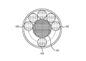
図2は、ライトガイド100の断面図である。図2に示されるように、ライトガイド100は、一本の第1光ファイバ束101と、数本の第2光ファイバ束102とを、備えている。
FIG. 2 is a cross-sectional view of the
第1光ファイバ束101は、束ねられた多数の石英ファイバからなる。但し、第1光ファイバ束101においては、石英ファイバは、縒られていない。なお、石英ファイバは、少なくともコアが石英ガラス(二酸化珪素)にて製造された光ファイバである。
The first
一方、第2光ファイバ束102は、束ねられつつ縒られた多数の多成分ファイバからなる。なお、多成分ファイバは、コア及びクラッドが多成分ガラス(ソーダ,石灰,及びシリカを主体とするガラス,又は、硼珪酸を主体とするガラス)にて製造された光ファイバである。
On the other hand, the second
そして、ライトガイド100は、第1光ファイバ束101を中心としてこの第1光ファイバ束101の周囲に第2光ファイバ束102が多数配置されることによって、一本のライトガイドとして、構成されている。従って、第1光ファイバ束101は、ライトガイド100内の中央部に位置し、第2光ファイバ束102は、ライトガイド100内の周縁部に位置することとなる。
The
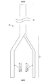
なお、ライトガイド100は、挿入部11,操作部12,及びケーブル部13に組み込まれる部分については、上記のように一本に構成されているが、コネクタ部14に組み込まれる部分においては、二本に分岐された二股となっている。図3は、ライトガイド100の基端部が二股に分岐している様子を示した図である。
The
このライトガイド100の基端部において分岐されたうちの一本は、上記の第1光ファイバ束101そのものであり、もう一本は、その残りである上記の数本の第2光ファイバ束102を束ねて一本に纏めたものである。
One of the branches at the proximal end of the
このライトガイド100における第1光ファイバ束101の基端と、第2光ファイバ束を束ねたものの基端とは、コネクタ部14の端面から突出する二本の金属パイプ14b,14c内に、それぞれ挿入されており、このコネクタ部14がプロセッサ装置のコネクタ受けに装着された際には、何れも、プロセッサ装置内の光源部内に挿入される。
The proximal end of the first
なお、その光源部は、体腔内を照明するための照明光,及び、体腔壁下の生体組織を励起させるための励起光の何れか一方を、ライトガイド100の各基端面に供給する。照明光及び励起光の何れをライトガイド100に供給するかは、体腔内を照明光にて観察するための通常観察モード,及び、励起した体腔壁から発せられる蛍光を観察するための特殊観察モードの何れかが選択されることにより、決定される。
The light source unit supplies illumination light for illuminating the inside of the body cavity and excitation light for exciting the living tissue under the body cavity wall to each base end face of the
また、この光源部は、上記の通常観察モードにおいて、又は、通常観察モード及び特殊観察モードとは別の観察モードにおいて、ライトガイド100における第1光ファイバ束101の基端面に対し、施術用のレーザービームを供給する。第1光ファイバ束101は、開口数の小さい石英ファイバにより構成されるため、第1光ファイバ束101にのみレーザービームを供給することにより、レーザービームの照射エネルギーが分散せず、且つ、被写体にスポット照射することができる。
In addition, the light source unit is used for the treatment with respect to the base end face of the first
本実施形態の軟性内視鏡10は、以上に示されるように構成されているため、以下に記述されるような効果を、有している。
Since the
図4は、励起光が本実施形態のライトガイド100に供給されてその先端から射出されたときの照射範囲と強度分布とを示す説明図である。また、図5は、石英ファイバと多成分ファイバとの分光透過率を示すグラフである。また、図6は、束ねられた多数の石英ファイバのみからなる従来のライトガイド100から励起光が射出されたときの照射範囲と強度分布とを示す説明図である。
FIG. 4 is an explanatory diagram showing an irradiation range and an intensity distribution when excitation light is supplied to the
まず、石英ファイバのみからなる従来のライトガイドによると、図6に示されるように、照射領域における中央部分の強度が落ち込むこととなる。一方、本実施形態では、開口数が小さくて透過率の高い石英ファイバからなる第1光ファイバ束101が、ライトガイド100内の中心部に位置していることにより、照射領域の中央部分の強度を向上させる。然も、開口数が大きくて透過率がやや低い多成分ファイバからなる第2光ファイバ束102が、ライトガイド100内の周縁部に位置していることにより、第1光ファイバ束101による照射領域における中央部分の強度とのバランスが取れて、全体としてガウス分布型の強度分布が形成されることとなる。その結果、照射領域における中央部分の強度の落ち込みが生ぜず、従来のライトガイドのような照射ムラが生じないようになっている。そのうえ、第1光ファイバ束101においては、石英ファイバは縒られていないため、第1光ファイバ束101が挿入部11の湾曲部11bに組み込まれても、湾曲部11bの湾曲によって石英ファイバが折れる心配はない。
First, according to a conventional light guide made of only quartz fiber, as shown in FIG. 6, the intensity of the central portion in the irradiation region falls. On the other hand, in the present embodiment, since the first
また、石英ファイバのみからなる従来のライトガイドによると、石英ファイバの開口数が小さいことから、図6に示されるように、その照射領域は比較的狭くなっている。一方、本実施形態では、石英ファイバよりも開口数の大きい多成分ファイバからなる第2光ファイバ束102が、ライトガイド100内の周縁部に位置していることにより、従来のライトガイドに比べて、照射領域が拡大されている。然も、第2光ファイバ束102では、多成分ファイバが縒られているため、縒られていない光ファイバ束に比べて、更に、照射領域が拡大されている。
Further, according to the conventional light guide made of only the quartz fiber, since the numerical aperture of the quartz fiber is small, the irradiation area is relatively narrow as shown in FIG. On the other hand, in the present embodiment, the second
なお、多成分ファイバは、図5の分光透過率のグラフに示されるように、可視帯域中の短波長側の光や紫外領域の光については、石英ファイバのそれに比べて低い透過率を有するものの、ゼロではない。そのため、本実施形態のライトガイド100は、可視帯域中の短波長側の光や紫外領域の光も、確実に照射することができる。実際に、ライトガイド100を製造する際には、照射領域における中央部分の強度の落ち込みを防ぎつつ、照射される励起光の全体の強度が最大となるように、第1光ファイバ束101と第2光ファイバ束102の混合比を決定することが望ましい。
As shown in the spectral transmittance graph of FIG. 5, the multi-component fiber has a lower transmittance for light on the short wavelength side in the visible band and light in the ultraviolet region than that of the quartz fiber. , Not zero. Therefore, the
また、図2の断面図では、第2光ファイバ束102同士に隙間があるように表現されているが、これは説明の都合上抽象的に記載したものであり、実際にライトガイド100を製造する際に隙間が形成されることはない。隙間を形成しない方法としては、例えば、第2光ファイバ束102の直径が第1光ファイバ束101と同程度であれば、この隙間に多成分光ファイバを詰め込めば良い。また、例えば、第2光ファイバ束102の直径が第1光ファイバ束101に比べて十分小さければ、第2光ファイバ束102を第1光ファイバ束101の周囲に二重三重と径方向に沿って積層させれば良い。
Further, in the cross-sectional view of FIG. 2, the second
ところで、本実施形態では、ライトガイド100の基端部は、コネクタ部14における二つの金属パイプ14b,14cに挿入するために、二股に分岐されていた(図1及び図3参照)が、これに限定されるものではなく、分岐させないで一本のままにされていても良い。この場合、コネクタ部14には、一本の金属パイプだけを用意すれば済むが、レーザービームを第1光ファイバ束101に供給することが難しくなる。
By the way, in this embodiment, the base end portion of the
10 軟性内視鏡
11 挿入部
11a 軟性部
11b 湾曲部
11c 先端部
12 操作部
12a アングルノブ
12b スイッチ
12c 鉗子口
12d ホース継ぎ手
13 ケーブル部
14 コネクタ部
14a 端子部
14b 金属パイプ
100 ライトガイド
101 第1光ファイバ束
102 第2光ファイバ束
DESCRIPTION OF
Claims (4)
前記第1光ファイバ束を中心としてこの第1光ファイバ束の周囲に配置された多数の多成分ファイバとを備え、
前記各多成分ファイバが縒られている
ことを特徴とするライトガイド。 A first optical fiber bundle comprising a number of bundled quartz fibers;
A plurality of multi-component fibers disposed around the first optical fiber bundle with the first optical fiber bundle as a center,
A light guide, wherein each of the multicomponent fibers is twisted.
束ねられつつ縒られた多数の多成分ファイバからなる第2光ファイバ束とを備え、
前記第2光ファイバ束が、前記第1光ファイバ束を中心としてこの第1光ファイバ束の周囲に多数配置されている
ことを特徴とするライトガイド。 A first optical fiber bundle comprising a number of bundled quartz fibers;
A second optical fiber bundle comprising a number of multicomponent fibers that are twisted while being bundled,
A plurality of the second optical fiber bundles are arranged around the first optical fiber bundle around the first optical fiber bundle.
前記ライトガイドは、
束ねられた多数の石英ファイバからなる第1光ファイバ束と、
前記第1光ファイバ束を中心としてこの第1光ファイバ束の周囲に配置された多数の多成分ファイバとを備え、
前記各多成分ファイバが縒られている
ことを特徴とする内視鏡。 An endoscope incorporating a light guide for guiding light from the proximal end to the distal end of the insertion portion,
The light guide is
A first optical fiber bundle comprising a number of bundled quartz fibers;
A plurality of multi-component fibers disposed around the first optical fiber bundle with the first optical fiber bundle as a center,
An endoscope characterized in that each of the multi-component fibers is twisted.
前記ライトガイドは、
束ねられた多数の石英ファイバからなる第1光ファイバ束と、
束ねられつつ縒られた多数の多成分ファイバからなる第2光ファイバ束とを備え、
前記第2光ファイバ束が、前記第1光ファイバ束を中心としてこの第1光ファイバ束の周囲に多数配置されている
ことを特徴とする内視鏡。 An endoscope incorporating a light guide for guiding light from the proximal end to the distal end of the insertion portion,
The light guide is
A first optical fiber bundle comprising a number of bundled quartz fibers;
A second optical fiber bundle comprising a number of multicomponent fibers that are twisted while being bundled,
An endoscope in which a large number of the second optical fiber bundles are arranged around the first optical fiber bundle with the first optical fiber bundle as a center.
Priority Applications (1)
| Application Number | Priority Date | Filing Date | Title |
|---|---|---|---|
| JP2004110449A JP2005292670A (en) | 2004-04-02 | 2004-04-02 | Light guide and endoscope |
Applications Claiming Priority (1)
| Application Number | Priority Date | Filing Date | Title |
|---|---|---|---|
| JP2004110449A JP2005292670A (en) | 2004-04-02 | 2004-04-02 | Light guide and endoscope |
Publications (1)
| Publication Number | Publication Date |
|---|---|
| JP2005292670A true JP2005292670A (en) | 2005-10-20 |
Family
ID=35325625
Family Applications (1)
| Application Number | Title | Priority Date | Filing Date |
|---|---|---|---|
| JP2004110449A Withdrawn JP2005292670A (en) | 2004-04-02 | 2004-04-02 | Light guide and endoscope |
Country Status (1)
| Country | Link |
|---|---|
| JP (1) | JP2005292670A (en) |
Cited By (3)
| Publication number | Priority date | Publication date | Assignee | Title |
|---|---|---|---|---|
| WO2013089103A1 (en) * | 2011-12-13 | 2013-06-20 | オリンパス株式会社 | Illumination module having plurality of light-guide members |
| JP2018097031A (en) * | 2016-12-08 | 2018-06-21 | 株式会社住田光学ガラス | Optical fiber bundle |
| JP2024028836A (en) * | 2019-01-11 | 2024-03-05 | ショット コーポレーション | Optically enhanced high resolution image guide |
-
2004
- 2004-04-02 JP JP2004110449A patent/JP2005292670A/en not_active Withdrawn
Cited By (7)
| Publication number | Priority date | Publication date | Assignee | Title |
|---|---|---|---|---|
| WO2013089103A1 (en) * | 2011-12-13 | 2013-06-20 | オリンパス株式会社 | Illumination module having plurality of light-guide members |
| JP2013123477A (en) * | 2011-12-13 | 2013-06-24 | Olympus Corp | Radiation module having plurality of light guide members |
| CN103997947A (en) * | 2011-12-13 | 2014-08-20 | 奥林巴斯株式会社 | Illumination module having plurality of light-guide members |
| US9835782B2 (en) | 2011-12-13 | 2017-12-05 | Olympus Corporation | Irradiation module having light guides |
| JP2018097031A (en) * | 2016-12-08 | 2018-06-21 | 株式会社住田光学ガラス | Optical fiber bundle |
| JP2024028836A (en) * | 2019-01-11 | 2024-03-05 | ショット コーポレーション | Optically enhanced high resolution image guide |
| JP7629505B2 (en) | 2019-01-11 | 2025-02-13 | ショット コーポレーション | Optically enhanced high resolution image guide |
Similar Documents
| Publication | Publication Date | Title |
|---|---|---|
| US12357155B2 (en) | Endoscope-pipe | |
| US8221312B2 (en) | Endoscope | |
| JP2007252448A (en) | Endoscope insertion part | |
| JP5350643B2 (en) | Endoscope device | |
| JP7302816B2 (en) | Fiberscope with good insertability | |
| JP4794916B2 (en) | Endoscope and endoscope system | |
| JP5186232B2 (en) | Endoscope device | |
| JP2001128929A (en) | Endoscope | |
| JP2005292670A (en) | Light guide and endoscope | |
| JP5180704B2 (en) | Endoscope light guide | |
| JP2002209832A (en) | Endoscope | |
| US20050059857A1 (en) | Medical endoscope | |
| JP5283463B2 (en) | Endoscope | |
| EP0370115B1 (en) | Catheter for diagnosis and therapy | |
| JP2005237698A (en) | Flexible endoscope and light guide | |
| JP2010068930A (en) | Imaging apparatus and endoscope | |
| JP2010051606A (en) | Illumination optical system and endoscope using the same | |
| JP2563969B2 (en) | Endoscope for small diameter | |
| JP4586115B2 (en) | Ultra-thin endoscope | |
| JP3211141B2 (en) | Body lumen identification device | |
| JP5459663B2 (en) | Flexible tube bending device | |
| JPS62208020A (en) | Endoscope device | |
| JP2015131154A (en) | Endoscope and optical fiber protection tube | |
| JPH01293312A (en) | Fiber optic system | |
| CN119014789B (en) | Guidewires, catheters and endoscopes |
Legal Events
| Date | Code | Title | Description |
|---|---|---|---|
| A621 | Written request for application examination |
Free format text: JAPANESE INTERMEDIATE CODE: A621 Effective date: 20070315 |
|
| A711 | Notification of change in applicant |
Free format text: JAPANESE INTERMEDIATE CODE: A712 Effective date: 20080501 |
|
| A977 | Report on retrieval |
Free format text: JAPANESE INTERMEDIATE CODE: A971007 Effective date: 20080730 |
|
| A131 | Notification of reasons for refusal |
Free format text: JAPANESE INTERMEDIATE CODE: A131 Effective date: 20080805 |
|
| A761 | Written withdrawal of application |
Free format text: JAPANESE INTERMEDIATE CODE: A761 Effective date: 20080925 |