JP2005292564A - Image forming apparatus - Google Patents
Image forming apparatus Download PDFInfo
- Publication number
- JP2005292564A JP2005292564A JP2004109055A JP2004109055A JP2005292564A JP 2005292564 A JP2005292564 A JP 2005292564A JP 2004109055 A JP2004109055 A JP 2004109055A JP 2004109055 A JP2004109055 A JP 2004109055A JP 2005292564 A JP2005292564 A JP 2005292564A
- Authority
- JP
- Japan
- Prior art keywords
- image forming
- chassis
- forming apparatus
- casing
- unit
- Prior art date
- Legal status (The legal status is an assumption and is not a legal conclusion. Google has not performed a legal analysis and makes no representation as to the accuracy of the status listed.)
- Granted
Links
Images
Landscapes
- Control Or Security For Electrophotography (AREA)
- Fixing For Electrophotography (AREA)
- Electrophotography Configuration And Component (AREA)
Abstract
【課題】 タンデム型の画像形成装置を2体化して、それぞれのシャーシー間での熱の伝達を隔離することを目的とする。
【解決手段】 そこで、第1のシャーシーには未定着画像を形成する部分のみを、第2のシャーシー内には熱発生の要因となる定着器を設置するようにした。そしてシャーシー間の記録材搬送パスを構成する開口部に熱の往来を防止するためのエアフロー手段を設けた。
【選択図】 図1PROBLEM TO BE SOLVED: To separate two tandem type image forming apparatuses and isolate the heat transfer between the chassis.
Therefore, only a portion where an unfixed image is formed is provided in the first chassis, and a fixing device that causes heat generation is provided in the second chassis. An air flow means for preventing heat from coming and going is provided in the opening constituting the recording material conveyance path between the chassis.
[Selection] Figure 1
Description
本発明は、電子写真方式を用いた複写機、プリンタ、ファクシミリなどの画像形成装置に関する。 The present invention relates to an image forming apparatus such as a copying machine, a printer, and a facsimile using an electrophotographic system.
近年、画像形成装置は高解像度化、カラー技術の発展により、より高画質な画像出力が求められており、様々な方法が提案されている。 In recent years, an image forming apparatus is required to output an image with higher image quality due to higher resolution and development of color technology, and various methods have been proposed.
高画質画像出力を達成する方法の一つとして、記録材面と印字部のグロス値(反射率)の差を小さくすることが重要視されてきている。 As one of the methods for achieving high-quality image output, it is important to reduce the difference in gloss value (reflectance) between the recording material surface and the printing portion.
グロス差を縮めるにはトナーと記録材の間の定着性をあげることが好ま記録材されている。 In order to reduce the difference in gloss, it is preferable to improve the fixing property between the toner and the recording material.
この問題を解決するために、従来から、図6のように記録材の搬送経路に複数の定着器をおいて順次定着ニップを通過させることで定着性の向上を図る構成が提案されている(特許文献1)。 In order to solve this problem, a configuration has been conventionally proposed in which a plurality of fixing devices are placed in a recording material conveyance path as shown in FIG. Patent Document 1).
また、図7に示す従来の装置では、第2定着器を搭載したユニットを第1定着器を搭載した画像形成ユニットの側部に装着し、第1定着器のみに記録材を通過させるための記録材搬送経路と、第1定着器と第2定着器の双方に記録材を通過させるための記録材搬送経路とを切り替え自在な構成とされている。このような記録材搬送経路は、記録材への片面記録モードや両面記録モードなどのモードに応じて適宜切り替えられることが記載されている(特許文献2)。 Further, in the conventional apparatus shown in FIG. 7, a unit equipped with the second fixing device is mounted on the side of the image forming unit equipped with the first fixing device, and the recording material passes only through the first fixing device. The recording material conveyance path and the recording material conveyance path for allowing the recording material to pass through both the first fixing device and the second fixing device can be switched. It is described that such a recording material conveyance path can be appropriately switched according to a mode such as a single-sided recording mode or a double-sided recording mode for a recording material (Patent Document 2).
さらに、近年では、画像形成の高速化へのニーズが非常に高くなっており画像形成ステーションを複数(例えば、4つ)有した画像形成装置が注目されている。このように画像形成ステーションを複数有する装置では、中間転写ベルトの長尺化などにより装置が大型化してしまう傾向がある。
しかしながら、上述した構成を一つの画像形成装置本体内に搭載すると、以下の問題を生じる。
(1)内蔵物が増えるため画像形成装置の本体サイズが大型化してしまい、製造した画像形成装置をユーザー先へ納入設置するような状況において、輸送するための車両を大型化せざるを得なくなったり、輸送時にエレベーターに載せることができなくなるなど、輸送時に問題が生じてしまうことがあった。また、装置の重量アップのため装置を梱包する梱包材を補強せざるを得ずコストアップしてししまう問題もあった。
(2)画像形成ステーションを複数有することに伴い装置本体内の各種機器の実装密度が増すため、定着器と画像形成機器が従来よりも近接し、定着前に小粒径の低融点トナーが融着などの問題を起こしやすくなる。
However, when the above-described configuration is mounted in one image forming apparatus main body, the following problems occur.
(1) Since the number of built-in items increases, the size of the main body of the image forming apparatus increases, and in a situation where the manufactured image forming apparatus is delivered and installed to the user, the vehicle for transportation must be increased in size. In some cases, problems may arise during transportation, such as being unable to be placed on an elevator during transportation. In addition, there has been a problem that the packaging material for packing the device has to be reinforced to increase the weight of the device, resulting in an increase in cost.
(2) Since the mounting density of various devices in the main body of the apparatus increases due to having a plurality of image forming stations, the fixing device and the image forming device are closer than before, and the low melting point toner having a small particle size is melted before fixing. Prone to problems such as wearing.
本発明は、記録材に未定着画像を形成する画像形成手段と、記録材上の未定着画像を熱定着する定着手段、とを有し、第1の筐体と第2の筐体とに分離自在に構成した画像形成装置において、
前記画像形成手段を前記第1の筐体に配置し、前記定着手段を前記第2の筐体に配置したことを特徴とする。
The present invention includes an image forming unit that forms an unfixed image on a recording material, and a fixing unit that thermally fixes an unfixed image on the recording material, and includes a first casing and a second casing. In the image forming apparatus configured to be separable,
The image forming unit is arranged in the first casing, and the fixing unit is arranged in the second casing.
本発明によれば、画像形成手段への熱の影響を抑制することができる。さらに、画像形成手段への熱の影響を抑制しながらも画像形成装置の輸送時の問題を解決することができる。 According to the present invention, the influence of heat on the image forming unit can be suppressed. Furthermore, it is possible to solve the problem during transportation of the image forming apparatus while suppressing the influence of heat on the image forming means.
本発明を適用した電子写真画像形成装置の実施形態について図1から5を参照し具体的に説明する。 An embodiment of an electrophotographic image forming apparatus to which the present invention is applied will be specifically described with reference to FIGS.
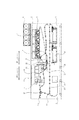
図1は、本発明に係る第1シャーシユニットと第2シャーシユニットを合体し最終的な形態を構成する画像形成装置の概略構成を模式的に示した断面説明図である。 FIG. 1 is a cross-sectional explanatory view schematically showing a schematic configuration of an image forming apparatus that combines a first chassis unit and a second chassis unit according to the present invention to form a final form.
本例の画像形成装置には、後述する画像形成ステーションが中間転写体に移動方向に沿って複数(4つ)並置されており、画像形成の高速化を図ることが可能な構成となっている。 In the image forming apparatus of the present example, a plurality of (four) image forming stations, which will be described later, are juxtaposed along the moving direction on the intermediate transfer member, so that the image forming speed can be increased. .
次に、図1を用いて、複数の画像形成ステーションのうちの1つについて具体的に説明するが、個々の画像形成ステーションの構成はほぼ同様である。 Next, one of the plurality of image forming stations will be described in detail with reference to FIG. 1, but the configuration of each image forming station is substantially the same.
そして、本例の画像形成装置は、第1の筐体としての第1シャーシー1と、第2の筐体としての第2シャーシー2とに分離自在な構成としている。
The image forming apparatus of this example is configured to be separable into a
このように、大サイズの画像形成装置を分離自在に連結した構成とすることで、画像形成装置をユーザー先へ納入設置するような状況において、エレベーターに分割して載せることができ、また、各シャーシーの重量を小さくできるので輸送効率を向上でき、更に梱包材補強のためのコストアップを防止することができる。 In this way, by having a configuration in which large-sized image forming apparatuses are separably connected, in a situation where the image forming apparatus is delivered and installed to a user, it can be divided and placed in an elevator. Since the weight of the chassis can be reduced, the transportation efficiency can be improved and the cost for reinforcing the packing material can be prevented.
第1シャーシー内に配置された画像形成ステーションは、画像形成手段の一部を構成する電子写真感光体(像担持体)3、画像形成手段の一部を構成する、所望の電位に帯電された感光体3表面をプリントを希望する画像情報に基づき画像露光して静電像を形成する露光部5、画像形成手段の一部を構成する、感光体上に形成された静電像に現像剤としてのトナーを付着させることによって顕像化する現像装置4、画像形成手段の一部を構成する、感光体上に顕像化された現像像を記録材(紙やOHPに代表される樹脂記録材等)に転写する転写手段7、を具備している。
6は現像装置に補給する現像剤を貯蔵したホッパー部である。
8はファンを用いて第1シャーシー内部の排気を行う抑制手段としての排気装置である。
9は記録材を給送する記録材給送部、10は転写後の記録材を第2シャーシー側へと搬送する第1ベルト搬送手段、11は第1シャーシーユニット側で転写された未定着画像を載せた記録材を第2シャーシー側へ搬送する第2ベルト搬送ユニットである。
The image forming station disposed in the first chassis is charged to a desired potential that forms part of the image forming unit, the electrophotographic photosensitive member (image carrier) 3 that forms part of the image forming unit. An
Reference numeral 6 denotes a hopper that stores developer supplied to the developing device.
9 is a recording material feeding section for feeding the recording material, 10 is a first belt conveying means for conveying the recording material after transfer to the second chassis side, and 11 is an unfixed image transferred on the first chassis unit side. It is a second belt conveyance unit that conveys a recording material on which an image is placed to the second chassis side.
第2シャーシー内に配置された12は、定着手段の一部を構成する、第1シャーシー内で像転写された記録材上の画像(現像剤像)を記録材に定着する第1定着器である。この第1定着器12は、メンテ・交換時を考慮して第2シャーシーの外へ引き出し自在な構成とされている。
13は第2シヤーシーユニット内の主に定着器の排熱を行う排気ダクトで、14は第1定着と第2定着の間を結ぶ搬送パスである。
第2シャーシー内に配置された15は、定着手段の一部を構成する、グロスコントロールして高画質化を達成するための第2定着器である。この第2定着器15は、メンテ・交換時を考慮して第2シャーシーの外へ引き出し自在な構成とされている。第1定着器と第2定着器は独立して第2シャーシーの外へ引き出し自在な構成とされている。
16は記録材の両面に画像を形成する際に再度画像形成部へ記録材を搬送・誘導するための再給紙搬送路、17は前記再給送する記録材を反転する反転パス、18は反転された記録材を現像装置まで搬送する両面パスである。
19は、現像装置や、感光体及び中間転写体をクリーニングするクリーニング装置からの廃トナーを貯蔵するボトルである。第2シャーシー内で定着器よりも下の両面搬送部よりさらに下のスペースに前記した廃トナーボトルを配置することで空きスペースを有効に使って廃トナーボトル容量を大きくすることが可能な上に、両面搬送ガイドにて定着器空間遮断されため、熱により廃トナーが解けてしまうことによる廃トナー搬送不良も防止できる。20は画像形成を終了した記録材を機外に排出する外排紙ローラー、21はキャスターである。
A
このように、本例では、画像形成を行う画像形成ステーションを第1シャーシー内に配置する一方、トナー画像を熱定着する2つの定着器を第2シャーシー内に配置することで、第2シャーシー内で発生した定着器による熱が第1シャーシー内へ進入するのを抑制するように構成されている。その結果、画像形成ステーションが熱の影響を受けることなく常時高画質画像を形成することが可能となる。 As described above, in this example, the image forming station for performing image formation is arranged in the first chassis, while the two fixing devices for heat-fixing the toner images are arranged in the second chassis. The heat generated by the fixing device is prevented from entering the first chassis. As a result, the image forming station can always form a high-quality image without being affected by heat.
また、次に説明するように、本例では、第1シャーシーと第2シャーシー間での熱の往来を抑制するような更なる工夫を施している。 In addition, as will be described below, in this example, a further contrivance is provided to suppress the passage of heat between the first chassis and the second chassis.
図2は前記したベルト搬送ユニットの詳細を説明するための図で、11aは吸引ファンで本実施例では遠心ファン(以下シロッコファン)を用いる、11bは吸引ファンからの排気を斜め下方側へと排気するための排気ダクトである。11cは図示せぬ吸引穴を複数持つ搬送ベルト、11dはベルト搬送ユニットフレーム、11eはベルト駆動ローラー、10fはベルト駆動モーターである。 FIG. 2 is a diagram for explaining the details of the belt conveying unit described above. 11a is a suction fan, and in this embodiment, a centrifugal fan (hereinafter referred to as a sirocco fan) is used, and 11b is an exhaust of the suction fan obliquely downward. An exhaust duct for exhausting air. 11c is a conveyance belt having a plurality of suction holes (not shown), 11d is a belt conveyance unit frame, 11e is a belt drive roller, and 10f is a belt drive motor.
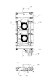
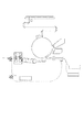
図3は.第1シャーシーユニットと第2シャーシーユニットの開口部周辺におけるエアー(排熱)の流れを説明する図で、30は第1シャーシーの柱、31は第2シャーシーの柱32は第2シャーシーに溶接された仕切り板部材である。33は第2シャーシーユニットの両面搬送から、第1シャーシーユニットの両面搬送に記録材を受け渡すための固定ガイド、34は第1シャーシーに溶接された仕切り板部材である。35は詳細を図示しないが2点差線で概略形状を示す引き出しユニットで、レジローラー、レジ前搬送部、第2転写ローラーと第1シャーシーユニットの両面搬送の左側を同一フレームに乗せて一体化したものを示す。 FIG. FIG. 6 is a diagram for explaining the flow of air (exhaust heat) around the openings of the first chassis unit and the second chassis unit, where 30 is a column of the first chassis, 31 is a column of the second chassis, and 32 is a second chassis. It is a welded partition plate member. Reference numeral 33 denotes a fixed guide for delivering the recording material from the double-sided conveyance of the second chassis unit to the double-sided conveyance of the first chassis unit, and 34 denotes a partition plate member welded to the first chassis. Although 35 is not shown in detail, 35 is a drawer unit showing a schematic shape with a two-point difference line, and the left side of the registration roller, the pre-registration conveyance unit, the second transfer roller and the first chassis unit on both sides is mounted on the same frame. Shows what
本実施例では、図3に示す矢印のようにエアフローが形成されており、図2にて説明した排気ダクト11bは第2シャーシー側から回り込んだ熱気を再び第2シャーシー側に戻すための形状を有している。
In this embodiment, an air flow is formed as indicated by the arrows shown in FIG. 3, and the
また、第1シャーシーユニットのさらに上流側で開口近傍のベルト搬送パス上部には、第1シャーシーユニットの排気装置9を配置して、吸気した空気を背面側から直接機外に排出するように構成している。図よりわかるように、この排気装置は、図示せぬフィルターを使用することにより、転写部で発生した浮遊トナーの吸引にも役立つように構成されている。 In addition, an exhaust device 9 of the first chassis unit is disposed further upstream of the first chassis unit and above the belt conveyance path in the vicinity of the opening so that the intake air is directly discharged from the rear side to the outside of the machine. It is configured. As can be seen from the figure, this exhaust device is configured to be useful for suction of floating toner generated in the transfer portion by using a filter (not shown).
以上の2つのエアフロー手段によって、ベルト搬送部用開口における、第2シャーシーユニットから第1シャーシーユニットへの熱の侵入は遮断されている。 The two airflow means described above block the heat intrusion from the second chassis unit to the first chassis unit in the belt conveyance unit opening.
また、第2ベルト搬送部の吸引ファン11aは画像形成装置がスタンバイ状態でも第2シャーシーユニットからの熱気の回り込みを防止するために駆動するように制御しておく。 Further, the suction fan 11a of the second belt conveyance unit is controlled so as to be driven in order to prevent hot air from flowing in from the second chassis unit even when the image forming apparatus is in a standby state.
本実施例は、ベルト搬送ユニットを第1、第2に分けることで、ベルト搬送ユニットの吸引ファンを可能な限り第1、第2シャーシの開口の接続部へ近づけることを可能としたため、スタンバイ時の熱気の回り込みを防止するのに、ひとつのベルト搬送ユニットのみで構成するよりも効果的である。 In this embodiment, the belt conveyance unit is divided into the first and second, so that the suction fan of the belt conveyance unit can be as close as possible to the connection portion of the opening of the first and second chassis. It is more effective to prevent the hot air from wrapping around than a single belt conveyance unit.
また、仕切り板32を第2シャーシー側に溶接することにより、ベルト搬送部にて接続される搬送パス上でのJAM処理スペースとして、第2シャーシー内部まで使用できる上に、排熱ダクト9を第2シャーシー側により近接させることが可能となる。 Further, by welding the partition plate 32 to the second chassis side, it can be used up to the inside of the second chassis as a JAM processing space on the transport path connected by the belt transport unit, and the exhaust heat duct 9 is connected to the second chassis. It becomes possible to make it closer to the two chassis side.
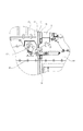
第2シャーシーユニット内では熱い空気は上昇していくため、ユニット天板に取り付いた排気ダクトを各定着器の上に配して、背面からファンによって熱気を吸引し機外に排出する。同一のシャーシー内に二つの定着器を配置したことで、図1のようにダクト部材は1つですむように構成できる。効率よく吸気できる形状にすることで排気ファンも1つで機能を達成可能とすることができる。 Since hot air rises in the second chassis unit, an exhaust duct attached to the unit top plate is arranged on each fixing device, and hot air is sucked from the back by a fan and discharged outside the apparatus. By arranging two fixing devices in the same chassis, it is possible to configure so that only one duct member is required as shown in FIG. By adopting a shape that allows efficient intake, it is possible to achieve the function with a single exhaust fan.
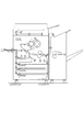
図4は第1シャーシー側から第2シャーシー側を見た概略図で、排熱ダクト13が第2シャーシー天板2aに取り付いていること、および、搬送パス14を奥ヒンジにて記録材のJAM処理時に開閉するために、前記ダクトの形状を斜めにしている部分があることを示している。図中40は排気ファンである。
FIG. 4 is a schematic view of the second chassis side as viewed from the first chassis side. The
第1定着器下の第2シャーシー側の両面搬送部は、JAM処理時には下ガイドを図示せぬ奥側のヒンジを中心として開閉するように構成してある。 The double-sided conveyance unit on the second chassis side below the first fixing unit is configured to open and close the lower guide around a hinge (not shown) at the back during JAM processing.
このとき、本実施例のように、ベルト搬送部の下の仕切り板部材を第1シャーシーに溶接することによって、第2シャーシーユニット両面搬送の第2シャー記録材第1シャーシーの受け渡し部ぎりぎりまでを開閉ガイドとして構成しながら、第2シャーシーユニット両面搬送上ガイドと前記した仕切り板によってJAM処理性を損なうことなく第1シャーシー、第2シャーシーユニット間を隔離することが可能となる。 At this time, as in this embodiment, the partition plate member under the belt conveyance unit is welded to the first chassis, so that the second chassis recording material double-sided conveyance of the second shear recording material first chassis reaches the limit. The first chassis and the second chassis unit can be isolated without impairing the JAM processability by using the second chassis unit double-sided transport upper guide and the above-described partition plate.
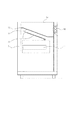
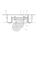
図5はキャスター取り付け構造を示す断面図で、45は底板部の天板、43は段ビスの足である。キャスター21は、弾性部材46をはさんで、底板部に溶接接合されたブラケット47に段ビス43とナット44によって締結される。前記した弾性部材は高画質機では一般的に免振ゴムが用いられている。
FIG. 5 is a cross-sectional view showing a caster mounting structure, 45 is a top plate of the bottom plate portion, and 43 is a step screw foot. The caster 21 is fastened by a
しかしながら、本発明のように二つのシャーシ間を記録材が往来する場合、シャーシ間の段差が発生すると搬送が不安定な状態になり好ましくない。また、アジャスターを追加して高さ調整するとコストアップになる。 However, when the recording material moves between two chassis as in the present invention, if a step between the chassis occurs, the conveyance becomes unstable, which is not preferable. In addition, adjusting the height by adding an adjuster increases the cost.
特に、本例のような画像形成装置では、第1シャーシと第2シャーシを分離した状態で輸送し、設置先にて両者を連結する作業を行う構成となることから、従来の、第1シャーシと第2シャーシの高さを調整する調整手段を別途設けて、連結時にこの高さ調整を行うには設置作業の時間が長くなってしまう可能性があった。 In particular, in the image forming apparatus as in this example, since the first chassis and the second chassis are transported in a separated state and the two are connected at the installation destination, the conventional first chassis is provided. In order to adjust the height at the time of connection by separately providing an adjusting means for adjusting the height of the second chassis, the installation work may take a long time.
そこで、本発明では第1シャーシユニットと第2シャーシユニットの重量差による、しずみ量の差を前記したキャスターの取り付け高さを変えることなく、第1シャーシーユニット、第2シャーシーユニットの各々で異なる硬度の弾性部材を使用してキャンセルしている。 Therefore, in the present invention, the difference in the amount of the stain due to the difference in weight between the first chassis unit and the second chassis unit does not change the mounting height of the casters, and the first chassis unit and the second chassis unit each. Canceled by using elastic members of different hardness.
即ち、第1シャーシー側の重量が第2シャーシー側よりも重い構成となっているので、本例では第1シャーシー側の上記弾性部材の硬度を第2シャーシー側の上記弾性部材の硬度よりも硬い構成としている。このようにすれば、アジャスターレスの構成とすると共に型投資の大きいブラケット部材を二つのシャーシー間で共通使用する構成であるにも関わらず、第1シャーシーと第2シャーシーの重量差による沈み量の差を良好にキャンセルすることが可能となる。 That is, since the weight on the first chassis side is heavier than that on the second chassis side, the hardness of the elastic member on the first chassis side is harder than the hardness of the elastic member on the second chassis side in this example. It is configured. In this way, the amount of sinking due to the difference in weight between the first chassis and the second chassis can be achieved despite the fact that the bracket is an adjuster-less structure and the bracket member having a large mold investment is commonly used between the two chassis. The difference can be canceled satisfactorily.
本例によれば、各々のシャーシの沈み量が弾性部材の硬度により自動的に調整されるので、設置に伴う作業時間を短縮化することができる。 According to this example, since the amount of sinking of each chassis is automatically adjusted according to the hardness of the elastic member, the work time associated with installation can be shortened.
以上説明したような構成にて、画像形成装置を第1シャーシーユニットと第2シャーシーユニットに分割自在な構成とすることで、画像形成装置を設置前は別々に輸送可能となり、梱包形態もエレベーター輸送に耐える大きさとすることが十分可能となる。 With the configuration as described above, the image forming apparatus can be divided into the first chassis unit and the second chassis unit, so that the image forming apparatus can be transported separately before installation, and the packaging form is also provided. It is possible to make it large enough to withstand elevator transportation.
なお、本発明の変形例として、2つの搬送ベルトユニットを用いない場合、前記した、第1シャシーに設置された排気装置をスタンバイ中も駆動することで同様の効果を得ることも可能である。 As a modification of the present invention, when two transport belt units are not used, the same effect can be obtained by driving the exhaust device installed in the first chassis during standby.
また、定着手段としての定着器が1つのみ設けられるような構成としても良く、この場合もこの1つの定着器を第1シャーシ側ではなく第2シャーシー側に配置することで、第1シャーシー側の画像形成機器が定着手段による熱の影響を受けることを可及的に少なくすることができる。 In addition, a configuration in which only one fixing device as a fixing unit is provided may be provided. In this case as well, the one fixing device is arranged on the second chassis side instead of the first chassis side, so that the first chassis side is arranged. It is possible to reduce as much as possible that the image forming apparatus is affected by heat from the fixing unit.
なお、高画質、高画像生産性のために定着器を複数設ける場合は定着器による熱の問題は顕著になることから、この場合には全定着器を第2シャーシ側に設置することは特に有効である。 In the case where a plurality of fixing devices are provided for high image quality and high image productivity, the problem of heat caused by the fixing device becomes significant. In this case, it is particularly preferable to install all the fixing devices on the second chassis side. It is valid.
1 第1シャーシー
2 第2シャーシー
12 第1定着器
15 第2定着器
DESCRIPTION OF
Claims (8)
前記画像形成手段を前記第1の筐体に配置し、前記定着手段を前記第2の筐体に配置したことを特徴とする画像形成装置。 An image forming unit that forms an unfixed image on a recording material, and a fixing unit that thermally fixes an unfixed image on the recording material, and is configured to be separable into a first housing and a second housing In the image forming apparatus,
An image forming apparatus comprising: the image forming unit arranged in the first casing; and the fixing unit arranged in the second casing.
前記第1の筐体と前記第2の筐体を弾性材を介してそれぞれ設置する構成とすると共に、これら弾性材の硬度を前記第1の筐体並びに前記第2の筐体の重量に応じて異ならせたことを特徴とする画像形成装置。 In the image forming apparatus configured to be transportable by being separated into the first casing and the second casing,
The first housing and the second housing are installed via elastic materials, and the hardness of these elastic materials depends on the weight of the first housing and the second housing. An image forming apparatus characterized by being different from each other.
Priority Applications (1)
| Application Number | Priority Date | Filing Date | Title |
|---|---|---|---|
| JP2004109055A JP4731825B2 (en) | 2004-04-01 | 2004-04-01 | Image forming apparatus |
Applications Claiming Priority (1)
| Application Number | Priority Date | Filing Date | Title |
|---|---|---|---|
| JP2004109055A JP4731825B2 (en) | 2004-04-01 | 2004-04-01 | Image forming apparatus |
Publications (3)
| Publication Number | Publication Date |
|---|---|
| JP2005292564A true JP2005292564A (en) | 2005-10-20 |
| JP2005292564A5 JP2005292564A5 (en) | 2007-05-24 |
| JP4731825B2 JP4731825B2 (en) | 2011-07-27 |
Family
ID=35325534
Family Applications (1)
| Application Number | Title | Priority Date | Filing Date |
|---|---|---|---|
| JP2004109055A Expired - Fee Related JP4731825B2 (en) | 2004-04-01 | 2004-04-01 | Image forming apparatus |
Country Status (1)
| Country | Link |
|---|---|
| JP (1) | JP4731825B2 (en) |
Cited By (6)
| Publication number | Priority date | Publication date | Assignee | Title |
|---|---|---|---|---|
| US20100215420A1 (en) * | 2009-02-23 | 2010-08-26 | Komiyama Tsutomu | Image forming apparatus |
| US20100215394A1 (en) * | 2009-02-24 | 2010-08-26 | Fuji Xerox Co., Ltd. | Image forming device |
| JP2012203086A (en) * | 2011-03-24 | 2012-10-22 | Canon Inc | Image forming device |
| JP2015105992A (en) * | 2013-11-29 | 2015-06-08 | キヤノン株式会社 | Image forming apparatus |
| JP2015105991A (en) * | 2013-11-29 | 2015-06-08 | キヤノン株式会社 | Image forming apparatus |
| US9310764B2 (en) | 2013-11-29 | 2016-04-12 | Canon Kabushiki Kaisha | Image forming apparatus |
Citations (1)
| Publication number | Priority date | Publication date | Assignee | Title |
|---|---|---|---|---|
| JPH0675441A (en) * | 1992-08-27 | 1994-03-18 | Katsuragawa Electric Co Ltd | Image forming device |
-
2004
- 2004-04-01 JP JP2004109055A patent/JP4731825B2/en not_active Expired - Fee Related
Patent Citations (1)
| Publication number | Priority date | Publication date | Assignee | Title |
|---|---|---|---|---|
| JPH0675441A (en) * | 1992-08-27 | 1994-03-18 | Katsuragawa Electric Co Ltd | Image forming device |
Cited By (8)
| Publication number | Priority date | Publication date | Assignee | Title |
|---|---|---|---|---|
| US20100215420A1 (en) * | 2009-02-23 | 2010-08-26 | Komiyama Tsutomu | Image forming apparatus |
| JP2010197457A (en) * | 2009-02-23 | 2010-09-09 | Fuji Xerox Co Ltd | Image forming apparatus |
| US9052648B2 (en) | 2009-02-23 | 2015-06-09 | Fuji Xerox Co., Ltd. | Image forming apparatus |
| US20100215394A1 (en) * | 2009-02-24 | 2010-08-26 | Fuji Xerox Co., Ltd. | Image forming device |
| JP2012203086A (en) * | 2011-03-24 | 2012-10-22 | Canon Inc | Image forming device |
| JP2015105992A (en) * | 2013-11-29 | 2015-06-08 | キヤノン株式会社 | Image forming apparatus |
| JP2015105991A (en) * | 2013-11-29 | 2015-06-08 | キヤノン株式会社 | Image forming apparatus |
| US9310764B2 (en) | 2013-11-29 | 2016-04-12 | Canon Kabushiki Kaisha | Image forming apparatus |
Also Published As
| Publication number | Publication date |
|---|---|
| JP4731825B2 (en) | 2011-07-27 |
Similar Documents
| Publication | Publication Date | Title |
|---|---|---|
| JP5884371B2 (en) | Image forming apparatus | |
| JP4226039B2 (en) | Developing device and image forming apparatus | |
| JP7243198B2 (en) | sheet ejection device, image forming device | |
| JP2022175261A (en) | image forming device | |
| JP5137452B2 (en) | Image forming apparatus | |
| JP4731825B2 (en) | Image forming apparatus | |
| CN101813900B (en) | Image forming apparatus | |
| JP2021009233A (en) | Image forming apparatus | |
| US8180249B2 (en) | Image forming apparatus | |
| JP5633832B2 (en) | Image forming apparatus | |
| JP2001255793A (en) | Image forming device | |
| JP2000066471A (en) | Image forming device | |
| JP2008096879A (en) | Image forming apparatus | |
| JPH04166956A (en) | Image forming apparatus | |
| JP4895166B2 (en) | Image forming apparatus | |
| JP2002278389A (en) | Filter fitting structure and image forming device with the same structure | |
| JP2017015894A (en) | Image forming apparatus, sheet guide | |
| JP6512171B2 (en) | Image forming device | |
| JP2001106384A (en) | Image forming device | |
| JP2013047840A (en) | Image forming apparatus | |
| JP2018054947A (en) | Image formation apparatus | |
| JP4058253B2 (en) | Image forming apparatus | |
| JP2006091705A (en) | Image forming apparatus | |
| JP2018054948A (en) | Image forming apparatus | |
| JP2006091784A (en) | Image forming apparatus |
Legal Events
| Date | Code | Title | Description |
|---|---|---|---|
| A521 | Written amendment |
Free format text: JAPANESE INTERMEDIATE CODE: A523 Effective date: 20070329 |
|
| A621 | Written request for application examination |
Free format text: JAPANESE INTERMEDIATE CODE: A621 Effective date: 20070329 |
|
| A977 | Report on retrieval |
Free format text: JAPANESE INTERMEDIATE CODE: A971007 Effective date: 20091210 |
|
| A131 | Notification of reasons for refusal |
Free format text: JAPANESE INTERMEDIATE CODE: A131 Effective date: 20091215 |
|
| RD04 | Notification of resignation of power of attorney |
Free format text: JAPANESE INTERMEDIATE CODE: A7424 Effective date: 20100201 |
|
| A521 | Written amendment |
Free format text: JAPANESE INTERMEDIATE CODE: A523 Effective date: 20100215 |
|
| RD01 | Notification of change of attorney |
Free format text: JAPANESE INTERMEDIATE CODE: A7421 Effective date: 20100630 |
|
| A131 | Notification of reasons for refusal |
Free format text: JAPANESE INTERMEDIATE CODE: A131 Effective date: 20100831 |
|
| A521 | Written amendment |
Free format text: JAPANESE INTERMEDIATE CODE: A523 Effective date: 20101029 |
|
| TRDD | Decision of grant or rejection written | ||
| A01 | Written decision to grant a patent or to grant a registration (utility model) |
Free format text: JAPANESE INTERMEDIATE CODE: A01 Effective date: 20110412 |
|
| A01 | Written decision to grant a patent or to grant a registration (utility model) |
Free format text: JAPANESE INTERMEDIATE CODE: A01 |
|
| A61 | First payment of annual fees (during grant procedure) |
Free format text: JAPANESE INTERMEDIATE CODE: A61 Effective date: 20110420 |
|
| FPAY | Renewal fee payment (event date is renewal date of database) |
Free format text: PAYMENT UNTIL: 20140428 Year of fee payment: 3 |
|
| R150 | Certificate of patent or registration of utility model |
Ref document number: 4731825 Country of ref document: JP Free format text: JAPANESE INTERMEDIATE CODE: R150 Free format text: JAPANESE INTERMEDIATE CODE: R150 |
|
| LAPS | Cancellation because of no payment of annual fees |