JP2005292555A - ELECTRONIC DISPLAY DEVICE AND METHOD FOR DRIVING THE SAME - Google Patents
ELECTRONIC DISPLAY DEVICE AND METHOD FOR DRIVING THE SAME Download PDFInfo
- Publication number
- JP2005292555A JP2005292555A JP2004108935A JP2004108935A JP2005292555A JP 2005292555 A JP2005292555 A JP 2005292555A JP 2004108935 A JP2004108935 A JP 2004108935A JP 2004108935 A JP2004108935 A JP 2004108935A JP 2005292555 A JP2005292555 A JP 2005292555A
- Authority
- JP
- Japan
- Prior art keywords
- frame data
- gradation
- data
- display
- divided
- Prior art date
- Legal status (The legal status is an assumption and is not a legal conclusion. Google has not performed a legal analysis and makes no representation as to the accuracy of the status listed.)
- Pending
Links
Images

Landscapes
- Control Of Indicators Other Than Cathode Ray Tubes (AREA)
- Control Of El Displays (AREA)
Abstract
【課題】 階調メモリのビット数を増やすことなく、簡単かつ廉価に、階調数を増やすことのできる電光表示装置の駆動方法を提案すること。
【解決手段】 電光表示装置1では、制御器3に供給される(2m−1)階調のフレームデータfrを分割数Dで分割し、これらD個の(2m−1)階調の各分割フレームデータfrdを、1フレームデータの転送周期内でLEDドライバIC5のmビットの階調メモリ7に転送している。したがって、各画素6のLEDは、1フレームデータの表示期間(転送期間)で見た場合に、(2m−1)×D(不点灯状態を除く)の階調数で駆動される。階調メモリ7のビット数を増やすことなく、フレームデータfrを表示するための階調数を増やすことができる。
【選択図】 図3PROBLEM TO BE SOLVED: To provide a driving method of an electro-optical display device capable of increasing the number of gradations easily and inexpensively without increasing the number of bits of the gradation memory.
In an electro-optical display device (1), (2 m -1) gradation frame data fr supplied to a controller (3) is divided by a division number D, and these D (2 m -1) gradation data are divided. Each divided frame data frd is transferred to the m-bit gradation memory 7 of the LED driver IC 5 within a transfer period of one frame data. Therefore, the LED of each pixel 6 is driven with the number of gradations of (2 m −1) × D (excluding the non-lighting state) when viewed in the display period (transfer period) of one frame data. The number of gradations for displaying the frame data fr can be increased without increasing the number of bits of the gradation memory 7.
[Selection] Figure 3
Description
本発明は、街角などに設置され、各種の広告、宣伝用の文字や映像を表示するために用いる電光表示装置に関するものである。更に詳しくは、階調表現用のメモリのビット数を増やすことなく、映像フレームデータを表示するための階調数を増やすことのできる電光表示装置の駆動方法に関するものである。 The present invention relates to an electric display device that is installed on a street corner or the like and is used to display various advertisements and promotional characters and images. More particularly, the present invention relates to a driving method of an electro-optical display device that can increase the number of gradations for displaying video frame data without increasing the number of bits of a memory for gradation expression.
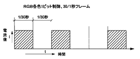
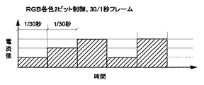
電光表示装置は、所定ピッチでマトリックス状にLEDなどの発光体が配列された電光表示パネルと、各発光体を駆動するためのドライバICと、ドライバICに表示データを供給する制御器から構成されている。制御器からは、一般に、毎秒30フレームのフレームデータがドライバICに供給される。ドライバICには、所定ビット数のメモリが搭載されており、例えば、1ビットメモリが搭載されている場合には、図4に示すように、各発光体が1/30秒間隔でオンあるいはオフされる。かかる1ビット制御方式では、「1」の状態と「0」の状態の2段階の明るさ(階調)を表現できる。一般には、表示1画素が、RGB各色のLED群から構成されている。また、ドライバICに搭載されているメモリが2ビットメモリの場合には、図5に示すように、0ないし3の4段階の明るさ(階調)を表現できる2ビット制御方式により各発光体が駆動される。 The electro-optical display device includes an electro-optical display panel in which light emitters such as LEDs are arranged in a matrix at a predetermined pitch, a driver IC for driving each light emitter, and a controller that supplies display data to the driver IC. ing. From the controller, generally, frame data of 30 frames per second is supplied to the driver IC. The driver IC has a predetermined number of bits of memory. For example, when a 1-bit memory is mounted, each light emitter is turned on or off at 1/30 second intervals as shown in FIG. Is done. Such a 1-bit control method can express two levels of brightness (gradation), a “1” state and a “0” state. In general, one display pixel is composed of LED groups of RGB colors. Further, when the memory mounted on the driver IC is a 2-bit memory, as shown in FIG. 5, each light emitter is formed by a 2-bit control method capable of expressing four levels of brightness (gradation) from 0 to 3. Is driven.
電光表示装置では、その電光表示パネルのドライバICに搭載されているメモリのビット数を増加させないと、階調数を増やしてより精細な映像を表示できない。メモリのビット数を増加させるということはドライバICの交換を意味し、一般に電光表示パネル全体を交換しなければならない。大型の電光表示パネルは高価であるので、階調数を増やすためには費用が嵩むという問題点がある。 In the electro-optical display device, if the number of bits of the memory mounted on the driver IC of the electro-optical display panel is not increased, the number of gradations cannot be increased to display a more detailed image. Increasing the number of bits in the memory means replacing the driver IC, and generally the entire electric display panel must be replaced. Since a large-sized electric display panel is expensive, there is a problem that the cost increases to increase the number of gradations.
また、電光表示パネルのドライバICに搭載されているメモリの最大ビット数は一般に8ビットであり、したがって、表現可能な階調数の最大値が256階調である。このために、これ以上の階調数で映像を表示することは実際上不可能あるいは困難であり、高精細な映像表示ができないという問題点がある。 In addition, the maximum number of bits of the memory mounted on the driver IC of the electroluminescent display panel is generally 8 bits, and therefore the maximum value of the number of gradations that can be expressed is 256 gradations. For this reason, it is practically impossible or difficult to display an image with more gradations, and there is a problem that high-definition image display cannot be performed.
本発明の課題は、このような点に鑑みて、メモリのビット数を増やすことなく、簡単かつ廉価に階調数を増やすことのできる電光表示装置の駆動方法を提案することにある。 In view of the above, an object of the present invention is to propose a driving method of an electro-optical display device that can increase the number of gradations easily and inexpensively without increasing the number of bits of a memory.
上記の課題を解決するために、本発明は、文字、映像などを表示するために所定ピッチで1画素を構成する発光体が配列された電光表示パネルと、各発光体を点滅駆動する駆動回路と、1秒当りNフレームからなる表示映像のフレームデータを、前記駆動回路に転送する制御器とを有し、前記駆動回路は、各発光体を(2m−1)(m:正の整数)の階調(不点灯状態を除く。)で点灯させるためのmビットの階調メモリを備えている電光表示装置の駆動方法において、
(2m−1)階調の各フレームデータをD個(D:2以上の整数)のフレームデータに分割し、
これらD個の(2m−1)階調の分割フレームデータを、各フレームデータの転送期間内で前記駆動回路にシリアル転送し、
各画素を構成する発光体を、1フレームデータの表示期間で見た場合に、(2m−1)×D(発光体の不点灯状態を除く。)の階調で駆動して、各フレームデータの各画素データを表示することを特徴としている。
In order to solve the above-described problems, the present invention provides an electric display panel in which light emitters constituting one pixel are arranged at a predetermined pitch for displaying characters, videos, and the like, and a drive circuit that drives each light emitter to blink. And a controller for transferring frame data of a display image consisting of N frames per second to the drive circuit, wherein the drive circuit sets each light emitter to (2 m −1) (m: positive integer). In the driving method of the electro-optical display device including the m-bit gradation memory for lighting at the gradation (except the non-lighting state),
Each frame data of (2 m -1) gradations is divided into D (D: integer of 2 or more) frame data,
These D (2 m -1) gradation divided frame data are serially transferred to the drive circuit within the transfer period of each frame data,
When the illuminant constituting each pixel is viewed in the display period of one frame data, it is driven at a gradation of (2 m −1) × D (excluding the non-illuminated state of the illuminant), and each frame is driven. Each pixel data of the data is displayed.
また、本発明は、上記の方法により駆動される電光表示装置であって、
前記制御器は、
分割数Dを設定入力するための入力部と、
表示映像の各フレームデータの各画素データの階調レベルを(2m−1)×Dの表示用階調レベルに割り振る表示用階調レベル算出部と、
算出された前記表示用階調レベルに基づき、各フレームデータから、D個の(2m−1)ビット階調の分割フレームデータを生成する分割フレームデータ生成部と、
フレームデータ毎に生成されたD個の分割フレームデータを、各フレームデータの転送期間内でそれぞれ前記駆動回路にシリアル転送するデータ転送部とを備えていることを特徴としている。
The present invention also provides an electro-optical display device driven by the above method,
The controller is
An input unit for setting and inputting the division number D;
A display gradation level calculation unit that allocates the gradation level of each pixel data of each frame data of the display video to a display gradation level of (2 m −1) × D;
A divided frame data generation unit that generates D (2 m −1) bit gray scale divided frame data from each frame data based on the calculated display gray level;
A data transfer unit that serially transfers D pieces of divided frame data generated for each frame data to the driving circuit within a transfer period of each frame data is provided.
本発明では、mビットの階調メモリを備えた電光表示装置において、(2m−1)階調の各フレームデータをD個の分割フレームデータに分割し、これらD個の分割フレームデータを1フレームデータの転送期間内(転送周期)で駆動回路に転送している。したがって、各画素を構成する発光体が、1フレームデータの表示期間で見た場合に、(2m−1)×D(発光体の不点灯状態を除く。)の階調で駆動される。よって、階調メモリにより規定される階調数よりも多い階調数でフレームデータを表示できる。したがって、駆動回路側の階調メモリのビット数を増加させることなく、分割数Dを乗算した階調数まで階調数を増加させることができる。また、市販の最大階調数である256階調よりも階調数を増加させることもできる。 In the present invention, in an electro-optical display device having an m-bit gradation memory, each frame data of (2 m −1) gradations is divided into D divided frame data, and these D divided frame data are divided into 1 The frame data is transferred to the drive circuit within the transfer period (transfer cycle). Therefore, the light emitters constituting each pixel are driven with a gradation of (2 m −1) × D (excluding the non-lighting state of the light emitters) when viewed in the display period of one frame data. Therefore, the frame data can be displayed with a larger number of gradations than the number of gradations defined by the gradation memory. Therefore, the number of gradations can be increased to the number of gradations multiplied by the division number D without increasing the number of bits of the gradation memory on the driver circuit side. Further, the number of gradations can be increased from 256 gradations, which is the maximum number of gradations on the market.
さらに、かかる駆動方法を採用した本発明の電光表示装置では、電光表示パネルの側を交換することなく、制御器の側を交換あるいは変更するだけで、階調数を増加させることができる。よって、階調数の増加を、電光表示パネルを交換することなく廉価に実現できる。 Furthermore, in the electro-optical display device of the present invention that employs such a driving method, the number of gradations can be increased by replacing or changing the controller side without replacing the electro-optical display panel side. Therefore, an increase in the number of gradations can be realized at low cost without replacing the light-emitting display panel.
以下に、図面を参照して本発明を適用した電光表示装置の一例を説明する。 Hereinafter, an example of an electro-optical display device to which the present invention is applied will be described with reference to the drawings.
図1は本例の電光表示装置を示す概略ブロック図である。本例の電光表示装置1は、電光表示パネルユニット2と制御器3とを有しており、電光表示パネルユニット2は、一般に長方形をした扁平なパネル本体4と、パネル本体4の裏面に搭載されたLEDドライバIC5を備えている。パネル本体4の表面には、一定のピッチで各表示1画素6を構成するLEDあるいはLED群がマトリックス状に配列されており、LEDドライバIC5にはmビットの階調メモリ7が搭載されている。
FIG. 1 is a schematic block diagram showing an electro-optical display device of this example. The electro-
制御器3は、映像データが記憶された映像データメモリ11と、ここから読み出された映像のフレームデータをLEDドライバIC5に供給する制御部12を備えている。映像データは一般に256(8ビット)階調のデータである。制御部12は、マイクロコンピュータを中心に構成され、そのROM内に格納されている制御プログラムを実行することにより次の各部分として機能する。すなわち、表示映像の各フレームデータの各画素データの階調レベルを(2m−1)×D(D:2以上の整数)の表示用階調レベルに割り振る表示用階調レベル算出部21と、算出された表示用階調レベルに基づき、(21−1)階調の各フレームデータfrを生成し、これから、D個の(21−1)階調の分割フレームデータfrd(1)〜frd(D)を生成する分割フレームデータ生成部22と、フレームデータfr毎に生成されたD個の分割フレームデータfrd(1)〜frd(D)を、各フレームデータの転送期間内でそれぞれLEDドライバIC5にシリアル転送するデータ転送部23として機能する。また、制御器3には分割数Dを入力設定するための入力部24が接続されている。
The controller 3 includes a
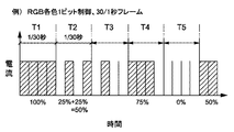
この構成の電光表示装置1の表示動作を説明する。まず、図2は、図4に示す1ビット制御方式に本発明を適用した場合の動作を示す説明図であり、階調メモリ7のビット数がm=1であり、フレームデータfrの転送速度は一般的な30フレーム/秒(N=30)である。この場合、映像データメモリ11から制御部12に供給される各フレームデータfrは256階調であり、各画素の階調数が表示用階調レベル算出部21において、表示用階調レベルに割り振られる。図示の例では、m=1、分割数D=4であり、表示用階調数は(21−1)×4=4(不点灯状態を除く。)であり、LEDの不点灯状態を入れると「5」である。表示用階調レベル算出部21では、256階調のフレームデータfrを4階調のフレームデータfrに変換する。
The display operation of the
次に、分割フレームデータ生成部22では、表示用階調レベルに従って、階調メモリ7のビット数m=1に対応した階調数(21−1=1、不点灯状態を入れて2)のフレームデータfrを生成し、このフレームデータfrを、4個の分割フレームデータfrd(1)〜frd(4)に分割する。すなわち、図2において、転送期間T1、T2、T3・・・がそれぞれ1フレームデータfrの転送期間(転送周期)である1/30秒であり、これを4分割した転送周期の分割フレームデータfrd(1)〜frd(4)を生成する。
Next, in the divided frame
ここで、生成に当っては、予め決められているアルゴリズムに従って、シリアル転送されるこれら4個の分割フレームデータfrd(1)〜frd(4)により、4つの階調レベルを表現できるようにする。1フレームデータにおける或る画素の表示用階調レベルが最も高い「4」の場合には、転送期間T1に示すように、全ての分割フレームデータfrd(1)〜frd(4)の対応画素データをレベル「1」(オン状態)に設定する。表示用階調レベルが「3」の場合には、転送期間T4に示すように、一つの分割フレームデータ、例えば3番目の分割フレームデータfrd(3)の当該画素データのみをレベル「0」(オフ)に設定する。 Here, in the generation, four gradation levels can be expressed by these four divided frame data frd (1) to frd (4) transferred serially according to a predetermined algorithm. . When the display gradation level of a certain pixel in one frame data is “4”, the corresponding pixel data of all the divided frame data frd (1) to frd (4) as shown in the transfer period T1. Is set to level “1” (ON state). When the display gradation level is “3”, as shown in the transfer period T4, only the pixel data of one divided frame data, for example, the third divided frame data frd (3) is set to the level “0” ( Set to Off.
このように設定された分割フレームデータfrd(1)〜frd(4)を1フレームデータの転送期間内にLEDドライバ5の階調メモリ7に転送する。この結果、1フレームデータの表示期間を見た場合に、LEDドライバ5によって、各フレームデータfrの各画素データが、最大「4」から最小「1」レベルまでの4段階(不点灯状態を入れると5段階)の階調で駆動された状態になる。 The divided frame data frd (1) to frd (4) set in this way are transferred to the gradation memory 7 of the LED driver 5 within the transfer period of one frame data. As a result, when the display period of one frame data is observed, each pixel data of each frame data fr is displayed by the LED driver 5 in four levels from the maximum “4” to the minimum “1” level (the non-lighting state is entered). And 5 levels).
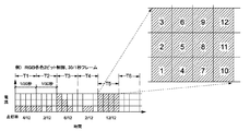
次に、図3は、図5の2ビット制御方式に本発明を適用した場合の動作を示す説明図であり、階調メモリ7のビット数がm=2であり、フレームデータfrの転送速度は一般的な30フレーム/秒である。この場合も、映像データメモリ11から制御部12に供給される各フレームデータfrは256階調であり、各画素の階調数が表示用階調レベル算出部21では、m=2であり、分割数がD=4であるので、表示用階調レベルは(22−1)×4=12であり、LEDの不点灯状態を入れると「13」となる。表示用階調レベル算出部21では、256階調のフレームデータfrを12階調(不点灯を入れた場合には13階調)のいずれかに割り当てる。
Next, FIG. 3 is an explanatory diagram showing the operation when the present invention is applied to the 2-bit control method of FIG. 5, the number of bits of the gradation memory 7 is m = 2, and the transfer rate of the frame data fr. Is a typical 30 frames / second. Also in this case, each frame data fr supplied from the
次に、分割フレームデータ生成部22では、表示用階調レベルに従って、3階調(=22−1)階調のフレームデータfrを生成し、このデータから、4個の分割フレームデータfrd(1)〜frd(4)を生成する。図3において、転送期間T1、T2、T3・・・がそれぞれ1フレームデータfrの転送期間(転送周期)である1/30秒であり、これを4分割した転送周期の分割フレームデータfrd(1)〜frd(4)を生成する。ここで、生成に当っては、これらの分割フレームデータにより12階調を表現できるように、予め決められているアルゴリズムに従って、各分割フレームデータにおける対応画素の階調レベルが「1」〜「4」(=分割数D)のいずれかとなるように、設定される。
Next, the divided frame
3階調の各分割フレームデータfr1(1)〜frd(4)は、1フレームデータの転送期間の間で、LEDドライバIC5の2ビットの階調メモリ7に供給される。これらの分割フレームデータに基づき表示パネルの各画素を形成しているLEDを駆動すると、1フレームデータの各画素が、1フレームデータの表示期間に亘って見た場合に、12階調で駆動されることになる。すなわち、図3に示すように、輝度は1フレームデータの駆動期間T1、T2、T3・・・における電力供給量に比例するので、12段階(不点灯状態を入れると13段階)の階調表現が可能である。 The divided frame data fr1 (1) to frd (4) of three gradations are supplied to the 2-bit gradation memory 7 of the LED driver IC 5 during the transfer period of one frame data. When the LEDs forming the pixels of the display panel are driven based on these divided frame data, each pixel of one frame data is driven with 12 gradations when viewed over the display period of one frame data. Will be. That is, as shown in FIG. 3, the luminance is proportional to the power supply amount in the driving period T1, T2, T3,. Is possible.
以上説明したように、本例では、文字、映像などを表示するために所定ピッチで発光体が配列された表示パネル4と、各発光体を点滅駆動するLEDドライバIC5と、1秒当りNフレームからなる表示映像のフレームデータfrを、LEDドライバIC5に転送する制御器3とを有し、LEDドライバIC5が、各発光体を(2m−1)(m:正の整数)の階調で点灯させるためのmビットの階調メモリ7を備えている電光表示装置1の駆動方法において、(2m−1)階調の各フレームデータfrをD個(D:2以上の整数)のフレームデータに分割し、これらD個の(2m−1)階調の分割フレームデータを各フレームデータの転送期間内でシリアル転送している。よって、LEDドライバIC5により、各発光体を、各フレームデータの表示期間において、(2m−1)×Dの階調数で駆動できる。
As described above, in this example, the
したがって、本例によれば、階調メモリ7のビット数を増加させることなく、分割数Dを増加させることにより、映像表示の階調数を増やすことができる。よって、表示パネルユニット2を交換することなく、制御器3の側のみを交換するだけで階調数を増やすことができるので、精細な映像表示を廉価に実現できる。 Therefore, according to this example, it is possible to increase the number of gradations of video display by increasing the division number D without increasing the number of bits of the gradation memory 7. Therefore, since the number of gradations can be increased by replacing only the controller 3 side without replacing the display panel unit 2, a fine video display can be realized at low cost.
1 電光表示装置
2 表示パネルユニット
3 制御器
4 表示パネル
5 LEDドライバIC
6 画素
7 階調メモリ
11 映像データメモリ
12 制御部
21 表示用階調レベル算出部
22 分割フレームデータ生成部
23 データ転送部
1 ELECTRONIC DISPLAY DEVICE 2 DISPLAY PANEL UNIT 3
6 pixels 7
Claims (2)
(2m−1)階調の各フレームデータをD個(D:2以上の整数)のフレームデータに分割し、
これらD個の(2m−1)階調の分割フレームデータを、各フレームデータの転送期間内で前記駆動回路にシリアル転送し、
各画素を構成する発光体を、1フレームデータの表示期間で見た場合に、(2m−1)×D(発光体の不点灯状態を除く。)の階調で駆動して、各フレームデータの各画素データを表示する電光表示装置の駆動方法。 An electric display panel in which light emitters constituting one pixel are arranged at a predetermined pitch for displaying characters, images, etc., a drive circuit for driving each light emitter to blink, and a frame of display video comprising N frames per second And a controller for transferring data to the driving circuit, and the driving circuit sets each light emitter at a gradation of (2 m −1) (m: positive integer) (excluding a non-lighting state). In a driving method of an electro-optical display device including an m-bit gradation memory for lighting,
Each frame data of (2 m -1) gradations is divided into D (D: integer of 2 or more) frame data,
The D (2 m -1) gradation divided frame data is serially transferred to the drive circuit within the transfer period of each frame data,
When the illuminant constituting each pixel is viewed in the display period of one frame data, it is driven at a gradation of (2 m −1) × D (excluding the non-illuminated state of the illuminant), and each frame is driven. A driving method of an electro-optical display device for displaying each pixel data of data.
前記制御器は、
分割数Dを設定入力するための入力部と、
表示映像の各フレームデータの各画素データの階調レベルを(2m−1)×Dの表示用階調レベルに割り振る表示用階調レベル算出部と、
算出された前記表示用階調レベルに基づき、各フレームデータから、D個の(2m−1)ビット階調の分割フレームデータを生成する分割フレームデータ生成部と、
フレームデータ毎に生成されたD個の分割フレームデータを、各フレームデータの転送期間内でそれぞれ前記駆動回路にシリアル転送するデータ転送部とを備えている電光表示装置。 An electro-optical display device driven by the method according to claim 1,
The controller is
An input unit for setting and inputting the division number D;
A display gradation level calculation unit that assigns the gradation level of each pixel data of each frame data of the display video to a display gradation level of (2 m −1) × D;
A divided frame data generation unit that generates D (2 m −1) -bit divided frame data from each frame data based on the calculated display gradation level;
An electro-optical display device comprising: a data transfer unit for serially transferring D divided frame data generated for each frame data to the drive circuit within a transfer period of each frame data.
Priority Applications (1)
| Application Number | Priority Date | Filing Date | Title |
|---|---|---|---|
| JP2004108935A JP2005292555A (en) | 2004-04-01 | 2004-04-01 | ELECTRONIC DISPLAY DEVICE AND METHOD FOR DRIVING THE SAME |
Applications Claiming Priority (1)
| Application Number | Priority Date | Filing Date | Title |
|---|---|---|---|
| JP2004108935A JP2005292555A (en) | 2004-04-01 | 2004-04-01 | ELECTRONIC DISPLAY DEVICE AND METHOD FOR DRIVING THE SAME |
Publications (1)
| Publication Number | Publication Date |
|---|---|
| JP2005292555A true JP2005292555A (en) | 2005-10-20 |
Family
ID=35325526
Family Applications (1)
| Application Number | Title | Priority Date | Filing Date |
|---|---|---|---|
| JP2004108935A Pending JP2005292555A (en) | 2004-04-01 | 2004-04-01 | ELECTRONIC DISPLAY DEVICE AND METHOD FOR DRIVING THE SAME |
Country Status (1)
| Country | Link |
|---|---|
| JP (1) | JP2005292555A (en) |
Cited By (1)
| Publication number | Priority date | Publication date | Assignee | Title |
|---|---|---|---|---|
| KR101373080B1 (en) | 2013-10-21 | 2014-03-25 | 주식회사 오라시스템 | System for realizing most significant bit image of 16bit chip using multi frame and method therefor |
Citations (1)
| Publication number | Priority date | Publication date | Assignee | Title |
|---|---|---|---|---|
| JPH0887002A (en) * | 1994-09-16 | 1996-04-02 | Hitachi Ltd | Liquid crystal display |
-
2004
- 2004-04-01 JP JP2004108935A patent/JP2005292555A/en active Pending
Patent Citations (1)
| Publication number | Priority date | Publication date | Assignee | Title |
|---|---|---|---|---|
| JPH0887002A (en) * | 1994-09-16 | 1996-04-02 | Hitachi Ltd | Liquid crystal display |
Cited By (1)
| Publication number | Priority date | Publication date | Assignee | Title |
|---|---|---|---|---|
| KR101373080B1 (en) | 2013-10-21 | 2014-03-25 | 주식회사 오라시스템 | System for realizing most significant bit image of 16bit chip using multi frame and method therefor |
Similar Documents
| Publication | Publication Date | Title |
|---|---|---|
| CN110379368B (en) | Driving method and driving device for pulse width and voltage mixed modulation and display device | |
| KR100858614B1 (en) | Organic light emitting display device and driving method thereof | |
| TWI389077B (en) | Organic light emitting diode display device and driving method thereof | |
| EP2590156A1 (en) | Method of sub-pixel rendering for a delta-triad structured display | |
| JP4980336B2 (en) | Liquid crystal display device and driving method thereof | |
| CN108257560A (en) | The method of organic light-emitting display device, data driver and driving data driver | |
| KR102325659B1 (en) | Organic Light Emitting Display Device | |
| CN110827768A (en) | Backlight device and display device having the same | |
| KR20130132702A (en) | Selective dimming to reduce power of a light emitting display device | |
| KR101158868B1 (en) | Liquid Crystal Display capable of adjusting each brightness level in plural divided areas and method for driving the same | |
| US10339851B2 (en) | Display apparatus, lighting control circuit, and method of lighting display apparatus | |
| TW201541441A (en) | Display device and method for driving the same | |
| US20090122001A1 (en) | Method and apparatus for image display with backlight illumination | |
| JP6037774B2 (en) | Video display device | |
| JP2021182070A (en) | Display device and source driver | |
| JP2000047637A (en) | Driving method of organic electroluminescence element and organic electroluminescence device | |
| US8767000B2 (en) | Data processing method and display apparatus for performing the same | |
| CN105632406A (en) | Display device and image control method | |
| JP2005524107A5 (en) | ||
| JP2006523322A (en) | Display device and method for sparking display pixels of such a device | |
| US10152909B2 (en) | Display apparatus | |
| JP2007536594A (en) | Color display device | |
| KR20230150964A (en) | Drive control device and drive control method, and information processing system | |
| KR101481072B1 (en) | Image display device having variable refresh rate according to gradation bit(data), image processing method and electronic display system using the same | |
| JP7287855B2 (en) | Display device |
Legal Events
| Date | Code | Title | Description |
|---|---|---|---|
| A621 | Written request for application examination |
Free format text: JAPANESE INTERMEDIATE CODE: A621 Effective date: 20061110 |
|
| A131 | Notification of reasons for refusal |
Free format text: JAPANESE INTERMEDIATE CODE: A131 Effective date: 20100223 |
|
| A02 | Decision of refusal |
Free format text: JAPANESE INTERMEDIATE CODE: A02 Effective date: 20100624 |