JP2005292511A - Development device - Google Patents
Development device Download PDFInfo
- Publication number
- JP2005292511A JP2005292511A JP2004108379A JP2004108379A JP2005292511A JP 2005292511 A JP2005292511 A JP 2005292511A JP 2004108379 A JP2004108379 A JP 2004108379A JP 2004108379 A JP2004108379 A JP 2004108379A JP 2005292511 A JP2005292511 A JP 2005292511A
- Authority
- JP
- Japan
- Prior art keywords
- developer
- container
- developing device
- developing
- chamber
- Prior art date
- Legal status (The legal status is an assumption and is not a legal conclusion. Google has not performed a legal analysis and makes no representation as to the accuracy of the status listed.)
- Pending
Links
Images

Landscapes
- Dry Development In Electrophotography (AREA)
Abstract
【課題】 現像容器内の現像剤の剤面を適正な位置に安定して維持することを可能とする現像装置、及びこれを備える画像形成装置を提供する。
【解決手段】 現像剤を収容する現像容器51であって、現像容器51内の現像剤を被現像体3に供給する現像剤担持体52と、現像容器51内の現像剤を搬送する現像剤搬送部材53と、現像容器51内の現像剤を溢出させることで現像容器51外に排出する現像剤排出口56と、を備える現像容器51と;現像剤を現像容器51に補給する現像剤剤補給手段55と;を有する現像装置5は、現像容器51に現像容器51内の現像剤の剤面Fを検知するための検知手段57Aを設けた構成とする。
【選択図】図2PROBLEM TO BE SOLVED: To provide a developing device capable of stably maintaining a developer surface in a developing container at an appropriate position, and an image forming apparatus provided with the developing device.
A developer container 51 that contains a developer, a developer carrier 52 that supplies the developer in the developer container 51 to the development target 3, and a developer that transports the developer in the developer container 51. A developer container 51 including a conveying member 53 and a developer discharge port 56 for discharging the developer in the developer container 51 to the outside of the developer container 51; a developer for supplying the developer to the developer container 51; The developing device 5 having the replenishing means 55 is configured such that a detecting means 57A for detecting the developer surface F of the developer in the developing container 51 is provided in the developing container 51.
[Selection] Figure 2
Description
本発明は、電子写真方式或いは静電記録方式を利用した複写機、プリンタ、ファクシミリなどの画像形成装置にて用いられる現像装置、及びこれを備える画像形成装置に関するものであり、より詳細には、トナーとキャリアとを備える現像剤を用いる現像装置、及びこれを備える画像形成装置に関するものである。 The present invention relates to a developing device used in an image forming apparatus such as a copying machine, a printer, and a facsimile using an electrophotographic method or an electrostatic recording method, and an image forming apparatus provided with the developing device. The present invention relates to a developing device using a developer including toner and a carrier, and an image forming apparatus including the same.
従来、例えば、電子写真方式の画像形成装置においては、トナーとキャリアとを備える混合剤である、所謂、2成分現像剤で現像を行う現像装置が広く用いられている。特に、カラー画像形成装置には画像の色味などの観点から、多くの現像装置が2成分現像剤を使用している。 2. Description of the Related Art Conventionally, for example, in an electrophotographic image forming apparatus, a developing device that performs development with a so-called two-component developer, which is a mixture including a toner and a carrier, is widely used. In particular, many developing devices use a two-component developer in the color image forming apparatus from the viewpoint of the color of an image.
2成分現像剤を用いる現像装置では、トナーは現像動作によって消費され、消費された量だけ新たなトナーが補給される。一方、キャリアは消費されずに現像容器(現像剤槽)内に残る。従って、トナーと共に攪拌されるキャリアは攪拌されることによって劣化する。キャリアの劣化は、現像剤を攪拌するときの摩擦や、現像容器に設けられた現像剤担持体(現像ローラなど)と現像剤層厚規制部材(規制ブレードなど)との隙間を通過する際の圧縮によって、キャリア表層にトナーが付着することによって生じる。キャリアが劣化すると、現像剤の帯電性能が低下し、現像性能が低下して画像不良の発生原因となる。そこで、定期的にキャリアを交換することが行われている。 In a developing device using a two-component developer, toner is consumed by a developing operation, and new toner is replenished by the consumed amount. On the other hand, the carrier remains in the developing container (developer tank) without being consumed. Therefore, the carrier stirred together with the toner is deteriorated by stirring. The deterioration of the carrier is caused by friction when stirring the developer or when passing through the gap between the developer carrier (developing roller, etc.) provided in the developing container and the developer layer thickness regulating member (regulating blade, etc.). This is caused by toner adhering to the carrier surface layer due to compression. When the carrier is deteriorated, the charging performance of the developer is deteriorated, and the developing performance is deteriorated to cause an image defect. Therefore, the carriers are regularly exchanged.
キャリアの交換は、現像容器に設けられている現像剤抜き取り口から現像剤を抜き取り、新しい現像剤を現像装置に充填するものである。この交換作業時には、粉体であるトナーが飛散し、画像形成装置及びその周囲を汚すことがある。 In the carrier replacement, the developer is extracted from the developer extraction port provided in the developing container, and a new developer is filled in the developing device. During this replacement operation, powder toner may scatter and stain the image forming apparatus and its surroundings.
そこで、現像剤の劣化を抑え、特別な現像剤交換作業を行わなくてもよい現像装置が提案されている(例えば、特許文献1参照。)。斯かる現像装置が採用する方式は、一般に、トリクル方式といわれ、現像装置のハウジング側壁の所定高さに溢出口を設け、トナーとキャリアとを備える現像剤を現像装置に補給することによって過剰になった現像装置内の現像剤を溢出口から順次排出することによって現像剤の特性を一定にするものである(例えば、特許文献2参照。)。 In view of this, there has been proposed a developing device that suppresses the deterioration of the developer and does not require special developer replacement work (see, for example, Patent Document 1). The method adopted by such a developing device is generally referred to as a trickle method, and is excessively provided by providing an overflow outlet at a predetermined height on the side wall of the housing of the developing device and replenishing the developing device with a developer including toner and a carrier. By sequentially discharging the developer in the developing device thus formed from the overflow outlet, the characteristics of the developer are made constant (for example, see Patent Document 2).
つまり、この方法は、現像容器内の現像剤の量が補給によって増加し、排出口よりも高くなった分だけ排出口から溢れ出させることによって現像剤を排出するものである。 That is, in this method, the amount of the developer in the developing container is increased by replenishment, and the developer is discharged by overflowing the discharge port by an amount higher than the discharge port.
しかしながら、従来の装置は、排出口に現像剤が滞った場合にそれを検知する手段がないために、現像剤の補給によって現像容器内の現像剤量が増加して現像容器内の現像剤の剤面(上面)が上昇し、画像濃度の変動やトナー飛散といった問題が生じることがある。又、現像剤量の増加によって現像剤担持体や現像容器内に配設された攪拌・搬送部材などの回転負荷が増し、現像装置或いは現像装置を駆動するための歯車やモータなどが損傷する虞がある。 However, since the conventional apparatus has no means for detecting when the developer stays in the discharge port, the amount of the developer in the developer container increases due to the replenishment of the developer, and the developer in the developer container The agent surface (upper surface) rises, and problems such as fluctuations in image density and toner scattering may occur. In addition, an increase in the developer amount may increase the rotational load on the developer carrying member and the agitating / conveying member disposed in the developing container, which may damage the developing device or the gear or motor for driving the developing device. There is.
又、現像装置を画像形成装置に配置した直後などは、現像容器内の現像剤が偏っていて、現像剤担持体が担持する現像剤の分布が不均一になり、画像の濃度ムラが生じることがあった。
本発明の目的は、現像容器内の現像剤の剤面を適正な位置に安定して維持することを可能とする現像装置、及びこれを備える画像形成装置を提供することである。 An object of the present invention is to provide a developing device that can stably maintain a developer surface in a developer container at an appropriate position, and an image forming apparatus including the developing device.
上記目的は本発明に係る現像装置及び画像形成装置にて達成される。要約すれば、第1の本発明は、現像剤を収容する現像容器であって、前記現像容器内の現像剤を被現像体に供給する現像剤担持体と、前記現像容器内の現像剤を搬送する現像剤搬送部材と、前記現像容器内の現像剤を溢出させることで前記現像容器外に排出する現像剤排出口と、を備える現像容器と;現像剤を前記現像容器に補給する現像剤補給手段と;を有する現像装置において、前記現像容器に前記現像容器内の現像剤の剤面を検知するための検知手段を設けたことを特徴とする現像装置である。本発明の一実施態様によると、前記検知手段の出力は、前記現像容器内の現像剤の剤面が通常状態より所定量上昇したときに変化する。又、本発明の他の実施態様によると、前記検知手段は、複数箇所、より詳細には、高さ方向に並べて配置して、前記複数の検知手段の出力は、前記現像容器内の現像剤の剤面が通常状態より上昇するに従い段階的に変化する。本発明の一実施態様によると、前記検知手段を前記現像剤搬送部材による現像剤の搬送方向に複数有する。そして、一実施態様では、前記複数の検知手段の出力に応じて、前記現像剤搬送部材の駆動速度を変更することができる。 The above object is achieved by the developing device and the image forming apparatus according to the present invention. In summary, the first aspect of the present invention is a developer container for storing a developer, the developer carrier for supplying the developer in the developer container to the development target, and the developer in the developer container. A developer container comprising: a developer conveying member to be conveyed; and a developer discharge port for discharging the developer in the developer container to overflow the developer container; and a developer for supplying the developer to the developer container And a replenishing device. The developing device is provided with a detecting means for detecting the developer surface of the developer in the developing container. According to an embodiment of the present invention, the output of the detection means changes when the developer level in the developer container rises by a predetermined amount from the normal state. According to another embodiment of the present invention, the detection means are arranged in a plurality of places, more specifically, in a height direction, and the output of the plurality of detection means is a developer in the developer container. It changes in stages as the surface of the liquid rises from the normal state. According to an embodiment of the present invention, a plurality of the detection means are provided in the developer transport direction by the developer transport member. In one embodiment, the driving speed of the developer conveying member can be changed according to the outputs of the plurality of detecting means.
第2の本発明によると、現像剤を被現像体に供給する現像剤担持体と、前記現像剤担持体の軸線方向に沿って現像剤を搬送する第1の現像剤搬送部材と、前記第1の現像剤搬送部材が収容される第1室と、前記第1の現像剤搬送部材と反対方向に現像剤を搬送する第2の現像剤搬送部材と、前記第2の現像剤搬送部材が収容され、前記第1室の略鉛直下方で前記第1室と略平行に配置されて両端部において前記第1室と連通する第2室と、を備える現像容器を有する現像装置であって、前記第1室内の現像剤の剤面を検知するための検知手段を、前記第1の現像剤搬送部材による現像剤の搬送方向に沿って複数有することを特徴とする現像装置が提供される。 According to the second aspect of the present invention, a developer carrier for supplying a developer to the development target, a first developer transport member for transporting the developer along the axial direction of the developer carrier, and the first A first chamber in which one developer conveying member is accommodated, a second developer conveying member that conveys the developer in a direction opposite to the first developer conveying member, and the second developer conveying member. A developing device having a developing container that is housed and includes a second chamber that is disposed substantially parallel to the first chamber below the first chamber and communicates with the first chamber at both ends; There is provided a developing device comprising a plurality of detection means for detecting the developer surface of the developer in the first chamber along a developer transport direction by the first developer transport member.
第3の本発明によると、現像剤を被現像体に供給する現像剤担持体と、前記現像剤担持体の軸線方向に沿って現像剤を搬送する第1の現像剤搬送部材と、前記第1の現像剤搬送部材が収容される第1室と、前記第1の現像剤搬送部材と反対方向に現像剤を搬送する第2の現像剤搬送部材と、前記第2の現像剤搬送部材が収容され、前記第1室の略鉛直下方で前記第1室と略平行に配置されて両端部において前記第1室と連通する第2室と、を備える現像容器を有する現像装置であって、前記第1室内の現像剤の剤面の勾配を検知するための検知手段を有することを特徴とする現像装置が提供される。 According to a third aspect of the present invention, a developer carrier for supplying a developer to a development target, a first developer transport member for transporting the developer along the axial direction of the developer carrier, and the first A first chamber in which one developer conveying member is accommodated, a second developer conveying member that conveys the developer in a direction opposite to the first developer conveying member, and the second developer conveying member. A developing device having a developing container that is housed and includes a second chamber that is disposed substantially parallel to the first chamber below the first chamber and communicates with the first chamber at both ends; There is provided a developing device having a detecting means for detecting the gradient of the developer surface of the developer in the first chamber.
第2、第3の本発明の一実施態様によると、前記検知手段の出力に応じて、前記第1の現像剤搬送部材及び前記第2の現像剤搬送部材の現像剤搬送速度を変更する。又、第2、第3の本発明の他の実施態様によると、前記検知手段の出力に応じて、前記現像剤担持体の現像剤搬送速度は変化する。 According to one embodiment of the second and third aspects of the present invention, the developer transport speeds of the first developer transport member and the second developer transport member are changed according to the output of the detection means. According to another embodiment of the second and third aspects of the present invention, the developer carrying speed of the developer carrying member changes according to the output of the detecting means.
又、第4の本発明によると、現像剤を収容する現像容器であって、前記現像容器内の現像剤を被現像体に供給する現像剤担持体と、前記現像容器内の現像剤を搬送する現像剤搬送部材と、前記現像容器内の現像剤を溢出させることで前記現像容器外に排出する現像剤排出口と、を備える現像容器と;現像剤を現像容器に補給する現像剤剤補給手段と;を有する現像装置において、前記現像剤排出口からの現像剤の排出を検知する検知手段を有することを特徴とする現像装置が提供される。本発明の一実施態様によると、更に、前記排出口から排出された現像剤を収容する現像剤回収容器を有し、前記検知手段は前記排出口から排出された現像剤の前記現像剤回収容器内への移動経路にて現像剤を検知する。 According to a fourth aspect of the present invention, there is provided a developer container for containing a developer, the developer carrier for supplying the developer in the developer container to the development target, and the developer in the developer container being conveyed. A developer transporting member, and a developer discharge port for discharging the developer in the developer container by overflowing the developer container, and supplying the developer to the developer container. And a developing device having a detecting means for detecting discharge of the developer from the developer discharge port. According to an embodiment of the present invention, the apparatus further includes a developer recovery container for storing the developer discharged from the discharge port, and the detection unit is the developer recovery container for the developer discharged from the discharge port. The developer is detected on the inward movement path.
更に、第5の本発明によると、その上に静電像が形成される被現像体としての像担持体と、上記各本発明の現像装置と、を有することを特徴とする画像形成装置が提供される。 Furthermore, according to a fifth aspect of the present invention, there is provided an image forming apparatus comprising: an image carrier as a developing object on which an electrostatic image is formed; and the developing devices according to the respective aspects of the present invention. Provided.
本発明によれば、現像容器内の現像剤の剤面を適正な位置に安定して維持することが可能となる。 According to the present invention, it is possible to stably maintain the developer surface of the developer in the developer container at an appropriate position.
以下、本発明に係る現像装置及び画像形成装置を図面に則して更に詳しく説明する。 Hereinafter, the developing device and the image forming apparatus according to the present invention will be described in more detail with reference to the drawings.
実施例1
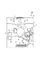
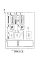
先ず、図1を参照して、本発明を適用し得る画像形成装置の一例の全体構成及び動作について説明する。本実施例の画像形成装置100は、画像形成装置本体(以下「装置本体」という。)1に接続された原稿の画像情報を光学的に読み取り電気信号に変換する画像読み取り部(リーダ部)Rからの画像情報信号に従って、記録材、例えば、記録用紙、OHPシート、布などに電子写真方式を用いて画像を形成する画像形成部(プリンタ部)Pを備える複写機である。画像形成装置100は、装置本体1に通信可能に接続されたパーソナルコンピュータなどの外部機器からの画像情報信号に従って画像を形成することもできる。
Example 1
First, an overall configuration and operation of an example of an image forming apparatus to which the present invention can be applied will be described with reference to FIG. The
画像形成装置100は、図中上方に画像読み取り部Rを有する。画像読み取り部Rは、読み取るべき原稿を載せる原稿台ガラス11を有する。原稿台ガラス11の下方には、原稿に光を照射するランプ12、反射ミラー12、レンズ13、光電変換素子15などが設けられている。これにより、原稿の画像情報を光学的に読み取り電気信号に変換して画像形成部Pに送ることができる。
The
画像読み取り部Rの図中下方には画像形成部Pが設けられている。画像形成部Pは、像担持体としての円筒状の電子写真感光体(以下「感光ドラム」という。)3を図中矢印方向に回転可能に有する。感光ドラム3の周囲には、感光ドラム3の表面を一様に帯電させる帯電手段たる帯電器4、露光手段たるレーザスキャナ2、感光ドラム3上に形成された静電潜像を現像剤のトナーによってトナー像として顕像化する現像装置5、感光ドラム3上のトナー像を記録材(シート材)Sに転写する転写手段たる転写帯電器6、感光ドラム3の表層に残留した残留トナーを回収するクリーナ7が配設されている。
An image forming unit P is provided below the image reading unit R in the drawing. The image forming portion P has a cylindrical electrophotographic photosensitive member (hereinafter referred to as “photosensitive drum”) 3 as an image carrier so as to be rotatable in the direction of the arrow in the figure. Around the
又、記録材供給部8は、記録材Sを収容するカセット81、記録材Sを給紙する記録材供給ローラ82、記録材Sを搬送する搬送ローラ83、記録材Sを所定のタイミングで送り出すタイミングローラ84などを有して構成される。更に、定着器9は、加熱ローラ91と加圧ローラ92とで構成され、記録材S上のトナー像を熱と圧力によって記録材Sに定着させる。
The recording material supply unit 8 also feeds the recording material S at a predetermined timing, a
画像形成プロセス自体は斯界にて周知であるので詳細な説明は省略するが、概略次の通りである。先ず、回転する感光ドラム3の表面を帯電器4によって一様に帯電させる。この帯電した感光ドラム3の表面を、画像読み取り部Rで読み取られた画像情報信号などに応じてレーザスキャナ2が走査露光し、感光ドラム3上に静電像を形成する。感光ドラム3上の静電像は、次いで、現像装置5が静電像に応じて現像剤のトナーを供給することによってトナー像とする。一方、感光ドラム3上へのトナー像の形成と同期するように、記録材供給部8から記録材Sが、感光ドラム3と転写帯電器6との対向部(転写部)へと搬送されてくる。こうして、感光ドラム3上のトナー像は、転写帯電器6の作用により記録材S上に静電的に転写される。トナー像が転写された記録材Sは、感光ドラム3から分離されて定着器9へと搬送される。そして、記録材S上の未定着トナー像は、定着器9の熱、圧力によって記録材Sに定着され、その後記録材Sは機外に排出される。又、転写工程後に感光ドラム3上に残留したトナー像は、クリーナ7によって除去され、感光ドラム3は、繰り返し画像形成に供される。
Since the image forming process itself is well known in the art, a detailed description thereof will be omitted, but is as follows. First, the surface of the rotating
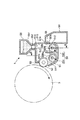
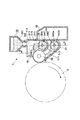
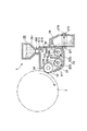
次に、図2、図3をも参照して現像装置5について更に詳しく説明する。図2は、本実施例の画像形成装置100が備える現像装置5の概略拡大断面を示す。又、図3は、図2中矢印A方向から見た概略断面図である。尚、以下の説明において、画像形成装置100の各要素についての上下、或いは鉛直方向とは、装置の適正な設置状態でのものをいう。
Next, the developing device 5 will be described in more detail with reference to FIGS. FIG. 2 shows a schematic enlarged cross section of the developing device 5 provided in the
本実施例では、現像装置5は、現像容器(現像剤槽)51、現像剤補給装置55、現像剤回収容器58を有して構成される。
In the present embodiment, the developing device 5 includes a developing container (developer tank) 51, a
現像容器51には、現像剤担持体としての現像ローラ52、現像剤を攪拌すると共に搬送する現像剤搬送部材53として第1、第2スクリュー531、532が回転自在に配設されている。そして、現像容器51内には現像剤が収容されている。現像容器51内の現像剤は、主にトナーとキャリアとを備える混合剤で、本実施例では、現像剤中のトナーの質量比(以下、T/D比とよぶ)は8%である。本実施例では、現像剤は、非磁性トナー粒子と、磁性キャリア粒子とを備える。その他、現像剤には、従来一般に行われているように、トナーの外添剤などの所望の組成が含まれていてよい。
In the developing
現像ローラ52は、感光ドラム3の軸線方向と略平行に延在する。又、第1、第2スクリュー531、532は、現像ローラ52の軸線方向と略平行、即ち、感光ドラム3の軸線方向と略平行に延在する。第1、第2スクリュー531、532は、それぞれ回転軸531a、532aの外周にスパイラル状の搬送部531b、532bを有する。そして、第1スクリュー531は図2の紙面に対し手前側から奥側に向かって回転軸方向に沿って現像剤を搬送し、第2スクリュー532は紙面に対して奥側から手前側に向かって回転軸方向に沿って現像剤を搬送する。
The developing
現像容器51の第1スクリュー531を収容する第1室(現像室)511と、第2スクリュー532を収容する第2室(攪拌室)512とは、仕切壁513で仕切られているが、現像ローラ52の長手方向に沿う現像容器51の長手方向両端部では第1室511と第2室512とは連通している。これによって、現像剤は、第1室511と第2室512との間で循環移動することができる。
The first chamber (development chamber) 511 that accommodates the
現像ローラ52は、その長手方向略全域にわたり、磁界発生手段としてのマグネットロールを内蔵している。これにより、摩擦帯電して表面にトナーが付着したキャリアは、現像ローラ52の表面に磁気拘束される。そして、現像ローラ52の回転に伴って、現像ローラ52と、これに対向して設けられた現像剤規制部材としての規制ブレード59との間を通過することで、現像ローラ52上の現像剤は、その量が規制され、感光ドラム3との対向部(現像部)に供給される。その後、現像部において、静電像に応じてトナーを感光ドラム3へと供給した後の現像剤は、更に現像ローラ52の回転に伴って搬送され、現像容器51内に回収される。
The developing
現像容器51の図2中上方に、現像剤補給手段としての現像剤補給装置55が設けられている。この現像剤補給装置55の補給剤収容部551に収容されている補給剤は、現像剤供給部材たる供給スクリュー552が回転駆動されることによって、補給口514から現像容器51へ補給される。本実施例では、補給口514は、第2室512の上方に設けられている。本実施例では、補給用の現像剤たる補給剤のT/D比は90%である。尚、ここでは、補給剤は既にキャリアとトナーとが混合されたものであるが、例えば補給剤収容部を2つ設けてキャリアとトナーとを各々に収容するようにして、それぞれを補給するか或いは互いに混合した後補給するかしてもよい。
A
現像容器51の壁面、より詳細には、第2室512の第2スクリュー532の軸線方向に沿う後壁515には、現像剤排出口(以下「排出口」という。)56が設けられている。現像剤補給装置55から補給剤が供給され、現像容器51内の現像剤の量が増すと、排出口56から、排出口56の下側の縁部である排出口下部56aを越えた現像剤が溢れ出す。排出口56から溢れ出した現像剤は、現像剤回収容器58に収容される。
A developer discharge port (hereinafter referred to as “discharge port”) 56 is provided on the wall surface of the
補給剤の補給は、現像容器51内の現像剤のT/D比を、現像容器51に設けられる現像剤濃度センサ(光学センサ、インダクタンスセンサなど)によって直接検知したり、作像画像のドット数をカウントしたり、濃度検知用画像を感光ドラム3などに形成してその濃度を検知するなどして間接的に検知して、ほぼ使用したトナーに見合う量のトナーが補給されるように、適時現像剤補給装置55の供給スクリュー552の駆動が制御されることによって行われる。そして、補給剤を補給することで過剰になった現像容器51内の現像剤は、排出口56から溢れ出し、主にキャリアが現像剤回収容器58に回収される。本実施例では、排出口から溢れ出す現像剤は少なくともキャリアを含む。これにより、通常の状態では、現像容器51内の現像剤の剤面(現像容器51内に露出した上面)Fは、図3中ハッチングで示すように、ほぼ一定の高さに維持される。尚、自動現像剤補給制御自体は公知であり、又、本発明では利用可能な任意の方法を採用することができるので、これ以上の詳しい説明は省略する。
Replenishment of the replenishing agent is performed by directly detecting the T / D ratio of the developer in the developing
現像容器51の壁面、より詳細には、第2室512の第2スクリュー532の軸線方向に沿う後壁515には更に、排出口56からの現像剤の排出が適正に行われているかを検知する手段として、現像容器51内の剤面Fを検知するための検知手段たる圧電センサ57Aが配設されている。圧電センサ57Aは、当該圧電センサ57Aの位置(より詳細には圧電センサ57Aの検出位置:以下、圧電センサ57Aについての位置は、別に断りがない場合その検出位置をいうものとする。図中圧電センサ57Aは、その検出位置を図示している。)まで現像剤の剤面Fが上昇すると信号を変化させる。これにより、現像容器51内の剤面Fが圧電センサ57Aの高さまで達していることを検知することができる。
The wall of the developing
つまり、前述のように、従来の装置では、排出口に現像剤が滞った場合などに現像容器内の現像剤量が増加して、画像濃度の変動やトナー飛散といった問題が生じたり、現像剤量の増加によって現像剤搬送部材などの回転負荷が増し、現像装置或いは現像装置を駆動するための歯車やモータなどが損傷する虞がある。そこで、本発明は、現像容器内の現像剤が過剰になることを防止することができ、又、現像装置内の現像剤が過剰になることによる、画質の低下や現像剤の飛散、現像装置の損傷を抑制することのできる現像装置及び画像形成装置を提供することをも目的とする。 In other words, as described above, in the conventional apparatus, the amount of the developer in the developer container increases when the developer stays in the discharge port, causing problems such as fluctuations in image density and toner scattering, or the developer. As the amount increases, the rotational load on the developer conveying member or the like increases, which may damage the developing device or a gear or a motor for driving the developing device. Therefore, the present invention can prevent the developer in the developing container from becoming excessive, and the developer in the developing device becomes excessive, resulting in deterioration in image quality, scattering of the developer, and developing device. Another object of the present invention is to provide a developing device and an image forming apparatus capable of suppressing damage to the image forming apparatus.
更に説明すると、圧電センサ57Aは、通常状態における剤面Fより所定量だけ上方に配置する。本実施例では、圧電センサ57Aは、排出口下部56aよりも5mm上方に配置する。つまり、本実施例では、通常は、現像容器51内の剤面Fは、圧電センサ57Aよりもほぼ5mm下方の、排出口下部56aの高さとほぼ同じ位置に維持される。そして、排出口56が現像剤によって詰まってしまったり、或いは排出口下部56aに現像剤が堆積して実質的に排出口下部56aの高さを上げたようにしてしまい、現像剤の排出が適正に行われなかった場合に剤面Fが上昇し、5mm上昇したときに検知が可能になる。
More specifically, the
又、本実施例においては、圧電センサ57Aは、排出口56に対して、第2室512における現像剤搬送方向の上流に配置している。斯かる配置関係は、排出口56よりも更に外側に圧電センサ57Aを配置しなくてすむために、現像装置の大きさへの影響を与えない点で有利である。
In this embodiment, the piezoelectric sensor 57 </ b> A is disposed upstream of the
本実施例においては、補給口514は第2室512における現像剤搬送方向において排出口56より上流側に設けられており、この位置で現像剤補給装置55によって現像剤が補給されているため、圧電センサ57Aを排出口56に対して現像剤搬送方向上流に配置する場合、圧電センサ57A近傍の剤面Fは、排出口下部56aよりも若干高い位置にある。又、第2室512において現像剤は第2スクリュー532の回転によって搬送されているため、剤面Fは、図示のように、スクリューピッチ周期で波打っている。これらを考慮して、本実施例では、圧電センサ57Aを排出口下部56aよりも3mm〜8mm程度上方に配置することが好ましい。
In this embodiment, the replenishing
尚、図4に示すように、圧電センサ57Aは、排出口56に対して第2室512における現像剤搬送方向下流に配置してもよい。斯かる配置関係は、剤面Fの検知を排出口56の下流で行うため、滞りなく現像剤の排出が行われていれば現像剤の補給等によって剤面Fの高さが変動することがない点で有利である。このような配置とした場合、通常は、圧電センサ57Aの近傍での剤面Fは排出口下部56aよりも低い位置にあるので、圧電センサ57Aは、排出口下部56aよりも2mm〜7mm程度上方に配置することが好ましい。
As shown in FIG. 4, the piezoelectric sensor 57 </ b> A may be disposed downstream of the
勿論、排出口下部56aに対してどの程度圧電センサ57Aを上方に配置するかは、本発明を適用する現像装置の構成に応じて適宜選定し得るものである。
Of course, how much the
又、図3、図4に示す如く圧電センサ57Aを1つだけ配置した場合には、剤面Fが通常よりも高い位置に在るか否かを検知することができる。これに対して、図5に示すように、現像容器51内で高さ方向に圧電センサ57Aを複数配設して、現像剤の剤面Fを段階的に検知してもよい。この場合、複数の圧電センサ57Aは、上記同様、排出口56に対して上流に配置してもよいし、下流に配置してもよい。このように、現像剤の剤面Fの高さを段階的に検知できれば、排出口下部56aにトナーが堆積し始めている状態を把握することができる。即ち、現像容器51内の現像剤の剤面Fが通常レベルであるのか、上昇しつつある段階であるのか、警告すべきほど上昇したレベルでるのか、或いは直ちに装置を停止すべきほど上昇したレベルであるのかなど、段階的に検知することができる。
Further, when only one
更に、前述したように、第2室512において現像剤は第2スクリュー532の回転によって搬送されているため、現像剤の剤面Fはスクリューピッチ周期で波打っている。このため、現像剤の量によっては第2スクリュー532の回転周期で圧電センサ57Aの出力が変動することがある。そのため、圧電センサ57Aの出力は、第2スクリュー532の回転の少なくとも1周期以上にわたって複数回若しくは連続的に検知した結果を平均化して、現像剤の剤面Fを検知し、剤面Fが当該圧電センサ57Aの位置にあるのか否かを判断することが好ましい。
Further, as described above, since the developer is conveyed by the rotation of the
例えば、本実施例では、第2スクリュー532の回転数(回転速度)は360rpm、つまり毎秒6回転しているので、1秒間の圧電センサ出力を時間的に平均すれば、第2スクリュー532が6回転したときの平均的な剤面Fの位置を把握することができる。より具体的には、圧電センサ57Aの出力は次のようにして平均化して、圧電センサ57Aの位置に剤面Fがあるか否かを判断する。圧電センサ57Aは、検知面に現像剤が存在するか否かによってHiとLowの2値を出力する。50ms毎に20回(合計1秒間)にサンプリングした場合、Hiレベルが10回以下であれば剤面Fは検知レベルに達していないと判断し、11回以上の場合は検知レベルに達していると判断する。このようにすれば、剤面Fのスクリューピッチ周期の変動や突発的な粉面(剤面)Fの異常によって誤検知することがなく、剤面Fの位置を検知できる。
For example, in this embodiment, the rotation speed (rotational speed) of the
これにより、第2スクリュー532の回転周期による影響をなくすことができる。
Thereby, the influence by the rotation period of the
上述のようにして現像容器51内の剤面Fが通常の状態よりも高くなっていることが検知された場合、(i)現像剤補給装置55の供給スクリュー552を停止させる、(ii)画像形成部Pの動作を停止させる、(iii)装置本体1が備える表示部130(図6)、或いは装置本体1に対して通信可能に接続された外部機器の表示部での表示、若しくは、適当なアラーム音などの適当な通知手段によって、排出口56の詰まり(或いは排出口下部56aへの現像剤の堆積)により排出口56からの現像剤の排出が適正に行われておらず現像容器51内の現像剤の剤面Fが所定値より高くなっている旨を操作者に報知する、或いは、(iv)現像剤の詰まりが軽微である場合などに、現像装置5の第1、第2スクリュー531、532のみを回転させて現像剤循環を行い、排出口56の堆積トナーが落ちるようにする、ことのいずれか若しくは組み合わせの処理を行う。
When it is detected that the surface F in the developing
尚、上述のように、圧電センサ57Aを複数設けるなどして現像容器51内の剤面Fの位置を段階的に検知する場合には、上記のような各処理のいずれか若しくは組み合わせを段階的に行うことができる。
As described above, when the position of the agent surface F in the developing
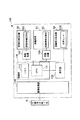
図6は、本実施例に係る制御回路ブロック図である。本実施例では、画像形成装置100は、装置本体1に、画像形成装置100の動作を統括的に制御する制御部110を有する。制御部110は、記憶手段(書き換え可能な不揮発性メモリとしてのEEEPROM、FeRAMなどを用いても良いし、ROMを用いても良い。:以下「メモリ」という。)112に記憶されたプログラム、データに従って画像形成装置100をシーケンス動作させる演算制御手段(以下「CPU」という。)111を有する。制御部110のCPU111には、現像容器51に設けられた圧電センサ57Aの出力が接続され、CPU111は、圧電センサ57Aの出力の変化から現像容器51内の現像剤の剤面Fが圧電センサ57Aの位置にあることを検知することができる。又、CPU11は、現像容器51に設けられた現像剤搬送部材53(第1スクリュー531、532)に駆動力を伝達する駆動装置(駆動モータ)を制御して、該現像剤搬送部材53の駆動の回転動作を制御する。更に、前述のように、CPU111は、検知した現像容器51内のT/D比に応じて、現像剤補給装置55の現像剤供給部材(供給スクリュー)552に駆動力を伝達する駆動装置(駆動モータ)140を制御して、該供給スクリュー552の回転動作を制御する。
FIG. 6 is a block diagram of a control circuit according to the present embodiment. In this embodiment, the
尚、制御部110には画像処理部120が接続されており、画像処理部120は、画像読み取り部R若しくは装置本体1に対し通信可能に接続された外部機器からの画像信号を受信すると共に、制御部30に画像形成に係る信号を送信する。制御部30は、斯かる画像形成信号に従って画像形成部Pの各部の動作を制御する。
An
そして、本実施例では、特に、CPU111は、メモリ112に記憶されたプログラム、データに従って、上述のように、排出口56の詰まり(或いは排出口下部56aへの現像剤の堆積)により排出口56からの現像剤の排出が適正に行われていないと判断した場合には、(i)現像剤補給装置55の供給スクリュー552を駆動する駆動装置140を停止させる、(ii)画像形成部Pの動作を停止させる、(iii)排出口56の詰まり(或いは排出口下部56aへの現像剤の堆積)により排出口56からの現像剤の排出が適正に行われておらず現像容器51内の現像剤の剤面Fが所定値以上になった旨を表示部130などに表示する、或いは(iv)現像剤搬送部材53(第1、第2スクリュー531、532を駆動する駆動装置150の駆動を制御して、現像装置5の第1、第2スクリュー531、532のみを駆動させる、ことのいずれか若しくは組み合わせの処理を実行させる。
In the present embodiment, in particular, the
又、上述したように、圧電センサ57Aの出力を平均化する場合、CPU111は、メモリ112に記憶されたプログラム、データに従って、圧電センサ57Aの出力を平均化して、現像容器51内の剤面Fの位置を判断する。
Further, as described above, when averaging the output of the
更に、上述のように、複数の圧電センサ37Aを設ける場合、CPU111は、メモリ112に記憶されたプログラム、データに従って、複数の圧電センサ57Aのうち剤面Fがあると検知した圧電センサ37Aの位置、数、組み合わせなどから、現像容器51内の現像剤の剤面Fの高さを段階的に検知する。そして、検知した現像容器51内の剤面Fのレベルに応じて、上記同様の処理のうちいずれか若しくは組み合わせを、段階的に実行することができる。
Further, as described above, in the case where a plurality of piezoelectric sensors 37A are provided, the
尚、本実施例では、剤面Fの位置を検知するための検知手段として圧電センサ57Aを用いた例を説明したが、本発明はこれに限定されるものではない。例えば、現像容器51の上方に超音波レベルセンサを配設して、超音波の反射を検知して剤面Fの位置を把握してもよい。或いは、剤面Fを、発光部(発光ダイオードなど)と受光部(フォトトランジスタなど)から成る光学センサを用いて検知してもよい。
In the present embodiment, the example in which the
以上、本実施例によれば、現像剤を逐次入れ替える現像装置5は、現像容器51内の現像剤の異常な増加を検知する構成とされるので、現像容器51内の剤面Fの安定化を図ることができる。そして、現像装置5の破損やトナー飛散を防止し、常に安定した画像を形成することができる。
As described above, according to the present embodiment, the developing device 5 that sequentially replaces the developer is configured to detect an abnormal increase in the developer in the
実施例2
次に、本発明の他の実施例について説明する。尚、本実施例の画像形成装置の基本構成及び動作は実施例1のものと同じであるので、実施例1のものと実質的に同一若しくは相当する機能、構成を有する要素には同一の符号を付して詳しい説明を省略する。
Example 2
Next, another embodiment of the present invention will be described. Since the basic configuration and operation of the image forming apparatus of the present embodiment are the same as those of the first embodiment, elements having substantially the same or corresponding functions and configurations as those of the first embodiment have the same reference numerals. A detailed description is omitted.
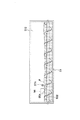
図7は、本実施例の画像形成装置100が備える現像装置5の概略断面を示す。本実施例では、現像剤搬送部材を鉛直方向に並べて複数配設している。
FIG. 7 shows a schematic cross section of the developing device 5 provided in the
つまり、現像装置5の現像容器51には、現像剤担持体としての現像ローラ52、現像剤を攪拌すると共に搬送する現像剤搬送部材54としての、現像ローラ52に現像剤を供給する現像剤供給スクリュー(第1スクリュー)541、現像剤供給スクリュー541の略鉛直下方に位置し、現像ローラ52からの現像剤を回収して搬送する現像剤回収スクリュー(第2スクリュー)542が回転自在に配設されている。
In other words, the
現像ローラ52は、感光ドラム3の軸線方向と略平行に延在する。又、第1、第2スクリュー541、542は、それぞれ回転軸541a、542aの外周にスパイラル状の搬送部541b、542bを有する。第1、第2スクリュー541、542は、現像ローラ52の軸線方向と略平行、即ち、感光ドラム3の軸線方向と略平行に延在する。第1、第2スクリュー541、542の現像剤搬送方向は相反する方向で、第1スクリュー541は図7の紙面に対し奥側から手前に向かって回転軸方向に沿って現像剤を搬送し、第2スクリュー542は紙面に対して手前側から奥側に向かって回転軸に沿って現像剤を搬送する。
The developing
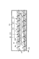
図8は、図7中の矢印B方向から見た概略断面図である。第1スクリュー541を収容する第1室(現像室)511と、第2スクリュー542を収容し第1室の略鉛直下方に位置する第2室(攪拌室)512とは、仕切壁(第1室511の底壁)513で仕切られているが、現像ローラ52の長手方向に沿う現像容器51の長手方向両端部では第1室511と第2室512とは連通している。
FIG. 8 is a schematic cross-sectional view seen from the direction of arrow B in FIG. A first chamber (developing chamber) 511 that accommodates the
現像剤は、第1、第2スクリュー541、542によって現像容器51の中を図8中矢印で示すように循環する。これと同時に、第1室511から現像ローラ52に供給され、現像工程に供された後に第2室512に回収される経路を経る現像剤もある。そのため、現像容器51内の現像剤は、図8中ハッチングで示すように、第1室511内においては現像剤の搬送に従って(図中左へ移動するに従い)現像ローラ52に現像剤が供給されることで量が減り、逆に第2室512内においては現像剤の搬送に従って(図中右へ移動するに従い)現像ローラ52から回収した現像剤が合流することで増加する。このように、第1室511、第2室512現像容器51内の現像剤の剤面Fは、第1室511、第2室512において、図示の通り、図中右に行くに従い高くなる勾配を有する。
The developer circulates in the developing
現像容器51の図7中上方に、現像剤補給装置55が設けられており、補給剤収容部551に収容されている補給剤は、供給スクリュー552が回転駆動されることによって、本実施例では、第1室511の上方に設けられている補給口514から第1室511内へと補給される。尚、現像容器51内の現像剤、現像剤補給装置55から現像容器51に補給する補給剤の組成は、実施例1と同じである。又、本実施例では、現像容器51の長手方向における補給口514の位置は、実施例1と同様である。
A
現像容器51の壁面、より詳細には、第1室511の第1スクリュー541の軸線方向に沿う後壁515には、排出口56が設けられている。現像剤補給装置55から補給剤が供給され、現像容器51内の現像剤の量が増すと、排出口56から、排出口下部56aを越えた現像剤が溢れ出す。排出口56から溢れ出した現像剤は、現像剤回収容器58に収容される。
A
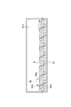
現像容器51の壁面、より詳細には、第1室511の第1スクリュー541の軸線方向に沿う後壁515には更に、実施例1と同様の圧電センサ57Aが配設されている。本実施例では、圧電センサ57Aは、第1室511の後壁515に、現像剤搬送方向に5箇所配設されている。実施例1と同様、圧電センサ57Aは、圧電センサ57Aまで現像剤の剤面Fが上昇すると信号を変化させる。これにより、剤面Fが圧電センサ57Aの高さまで達していることを検知できる。
On the wall surface of the developing
又、本実施例では、前述のように第1室511内の現像剤の剤面Fは勾配を持つため、それぞれの圧電センサ57Aの高さ方向の位置は、概ねその勾配に沿って配置する。
In the present embodiment, as described above, since the developer surface F of the developer in the
更に説明すると、本実施例では、5個の圧電センサ57Aのそれぞれは、それぞれ、通常状態における剤面Fより所定量だけ上方に配置される。本実施例では、通常は、それぞれの圧電センサ57Aの下方ほぼ5mmの高さに維持されるようになっている。そして、実施例1と同様、現像剤の排出が適正に行われなかった場合に剤面Fが上昇し、それぞれの圧電センサ57Aの位置で剤面Fが5mm上昇したときに検知が可能になる。
More specifically, in this embodiment, each of the five
又、上述のように、圧電センサ57Aを、概ね現像剤の剤面Fの勾配に沿って複数配置することにより、上記のように現像剤の剤面Fの上昇を検知できると共に、剤面Fの勾配の状況を把握することができる。このように、本実施例では、剤面Fを検知する複数の圧電センサ57Aは、現像容器51内の剤面Fの勾配を検知するための手段の複数の検知部を構成する。
Further, as described above, by arranging a plurality of
つまり、前述のように、従来、現像装置を画像形成装置に配置した直後などは、現像容器内の現像剤が偏っていて、現像剤担持体が担持する現像剤の分布が不均一になり、画像の濃度ムラが生じることがあった。従って、本発明は、現像容器内の現像剤の偏りを防止することができ、又、現像容器内の現像剤の剤面が所定量よりも大きく傾いていた場合に、これを適正にし、濃度ムラなどの画質低下を抑制することができる現像装置、及びこれを備える画像形成装置を提供することをも目的とする。 That is, as described above, the developer in the developing container is biased and the distribution of the developer carried by the developer carrying member becomes non-uniform immediately after the developing device is placed in the image forming apparatus. The density unevenness of the image may occur. Therefore, the present invention can prevent the bias of the developer in the developing container, and when the developer surface of the developer in the developing container is inclined more than a predetermined amount, It is another object of the present invention to provide a developing device capable of suppressing deterioration in image quality such as unevenness and an image forming apparatus including the developing device.
具体的には、5箇所の圧電センサ57Aの一つでも剤面の上昇を検知したときに、排出口56の詰まり(或いは排出口下部56aへの現像剤の堆積)により排出口56からの現像剤の排出が適正に行われていないか、若しくは現像剤の偏りが生じていると判断することができる。
Specifically, when any one of the five
尚、例えば、5箇所の圧電センサ57Aの内、図中の左側2個はLowであり、右側3個がHiを検知した場合に、現像剤の剤面Fの勾配が異常である、即ち、許容値を超えたと判断することができる。
For example, when the left two of the five
第1室511内の剤面Fの勾配が所定量よりも大きい場合には、第1スクリュー541と第2スクリュー542の回転速度を増し、前述した現像剤循環経路において現像ローラ52を経由しない方の経路の現像剤搬送速度を相対的に増やす。これによって、第1室511内の勾配を低減させることができる。
When the gradient of the agent surface F in the
ここで、第1スクリュー541及び第2スクリュー542が搬送する現像剤量が、現像ローラ52が搬送する現像剤量よりも相対的に十分大きければ、第1室511内の現像剤の剤面Fの勾配は小さくなるが、現像剤の攪拌搬送速度を増すことは現像剤の劣化を早めることに繋がる。そのため、第1、第2スクリュー541、542の現像剤搬送速度は、必要最低限の速度にすることが望ましい。本実施例では、現像容器51内の剤面Fの勾配を検知する手段、即ち、複数の圧電センサ57Aを有するので、環境変動などによって現像剤の攪拌搬送速度が変わることで現像容器51内の剤面Fの勾配が変わっても、それを検知して低減させることが可能になる。これにより、通常は、第1、第2スクリュー541、542の回転速度を必要最低限度に低く設定することが可能である。例えば、環境変動として、高湿度の環境においては、現像剤の剤面Fの勾配は、急になることがある。
Here, if the amount of developer conveyed by the
本実施例の現像装置5では、第1、第2スクリュー541、542の回転数が360rpmの時に剤面Fの勾配が許容値を超えていたものが、420rpmに回転速度を上げたところ剤面の勾配が許容範囲内に収まった。
In the developing device 5 of the present embodiment, when the rotation speed of the first and
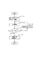
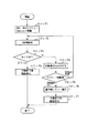
より具体的には、圧電センサ57Aの出力から第1室511内の現像剤が偏った、或いは剤面Fの勾配が許容値を越えたと判断した場合、図9に示すような処理を行う。即ち、通常、第1、第2スクリュー531、532を360rpmで駆動し(ステップ1)、5秒間駆動した際に(ステップ2)、圧電センサ57Aの出力を検知し(ステップ3)、圧電センサ57AのHiを検知した場合は、第1、第2スクリュー541、542の回転数を30rpm上げる(ステップ4)。その後5秒間第1、第2スクリュー541、542を駆動し(ステップ2)、再度、ステップ3の判断を行い、圧電センサ57AのHi信号を検知した場合は、第1、第2スクリュー541、542の回転数を30rpm上げる。一方、ステップ3の判断において全ての圧電センサ57AからLow信号を検知する場合には、第1、第2スクリュー541、542の回転数を上げることはせずに、作像終了後、装置の駆動を停止させる。この処理は、画像形成中であっても実行することができる。
More specifically, when it is determined that the developer in the
又、圧電センサ57Aの出力から第1室511内の現像剤が偏った、或いは剤面Fの勾配が許容値を越えたと判断した場合、図10に示すような処理を行ってもよい。即ち、通常、第1、第2スクリュー541、542を360rpmで駆動し(ステップ1)、5秒間駆動した際に(ステップ2)、圧電センサ57Aの出力を検知し(ステップ3)、圧電センサ57AのHiを検知した場合は、第1、第2スクリュー541、542の回転数を30rpm上げる(ステップ4)。そして、ステップ4にて第1、第2スクリュー541、542の回転数を30rpm上げた後、回転数が所定値(ここでは500rpm)以上であると判断した場合には、画像形成装置本体1が備える操作部に設けられた表示部130(図6)などに、現像容器51内の現像剤が偏っている或いは剤面Fの勾配が許容値を超えた旨のエラー表示を表示させる(ステップ6)。その後、作像終了後に装置の駆動を停止させる(ステップ7)。ステップ5の判断において、第1、第2スクリュー541、542の回転速度が500rpm未満であるなら、5秒間第1、第2スクリュー541、542を駆動し(ステップ2)、再度、ステップ3の判断を行い、圧電センサ57AのHi信号を検知た場合は、第1、第2スクリュー541、542の回転数を30rpm上げる。一方、ステップ3の判断において全ての圧電センサ57AからLow信号を検知する場合には、第1、第2スクリュー541、542の回転数を上げることはせずに、作像終了後、装置の駆動を停止させる。
Further, when it is determined from the output of the
尚、本実施例においても、実施例1と同様、それぞれの圧電センサ57Aの出力を平均化して、各圧電センサ57Aの位置に剤面Fがあるか否かを判断することができる。
In the present embodiment, similarly to the first embodiment, the outputs of the respective
本実施例の制御態様は、基本的に図6に示す実施例1のものと同様であるが、本実施例では、特に、CPU111は、メモリ112に記憶されたプログラム、データに従って、上述のように、現像容器51に設けられた複数の圧電センサ57Aの出力から、排出口56の詰まり(或いは排出口下部56aへの現像剤の堆積)により排出口56からの現像剤の排出が適正に行われておらず、現像容器51内の現像剤の剤面Fが上昇したことを判断することができる。そして、排出口56の詰まり(或いは排出口下部56aへの現像剤の堆積)により排出口56からの現像剤の排出が適正に行われていないと判断する場合は、実施例1と同様の処理を実行させることができる。
The control mode of the present embodiment is basically the same as that of the first embodiment shown in FIG. 6, but in this embodiment, the
又、本実施例においては、CPU111は、メモリ112に記憶されたプログラム、データに従って、上述のように、現像容器51に設けられた複数の圧電センサ57Aの出力から、現像剤攪拌搬送速度の変化などにより、現像容器51内の現像剤が偏っている或いは現像剤の剤面Fの勾配が許容値を越えていることを判断することができる。そして、現像容器51内の現像剤が偏っている或いは現像剤の剤面Fの勾配が許容値を越えたと判断する場合は、現像容器51内の第1、第2スクリュー541、541に駆動を伝達する駆動装置150の駆動を制御して、上述のような処理にて現像剤の剤面Fが適正になるようにする。
In the present embodiment, the
尚、本実施例においては、現像剤の剤面Fの勾配を適正にするために第1、第2スクリュー541、542の回転速度を増したが、これに限定されるものではない。例えば、現像ローラ52の回転数を下げる或いは停止して第1スクリュー541と第2スクリュー542のみを回転駆動しても、相対的に第1、第2スクリュー541、542の現像剤搬送量が増したことになる。但し、この場合は現像ローラ52が感光ドラム3にトナーを供給する能力が低下しているので、画像形成時以外の所定タイミングで行うことが望ましい。画像形成時以外の所定タイミングとしては、画像形成を行う前の準備動作である前回転時(若しくは画像形成を行った後の準備動作である後回転時)などが挙げられる。
In this embodiment, the rotational speeds of the first and
又、本実施例においては、現像剤の剤面Fの勾配を適正にするために第1、第2スクリュー541、542の回転速度を増したが、これに限定するものではなく、現像剤の剤面Fの勾配が許容値を越えていた場合、アラームなどで使用者に通知するようにしてもよい。
In this embodiment, the rotational speeds of the first and
以上、本実施例によれば、実施例1と同様の効果を得られると共に、更に、現像容器51内の現像剤の偏りを検知し、現像剤搬送部材54の現像剤搬送速度を適宜変えることによって、現像剤の劣化を最小限に留めながら、画像不良を防止することができる。
As described above, according to the present embodiment, the same effects as those of the first embodiment can be obtained, and further, the deviation of the developer in the
実施例3
次に、本発明の他の実施例について説明する。尚、本実施例の画像形成装置の基本構成及び動作は実施例1のものと同じであるので、実施例1のものと実質的に同一若しくは相当する機能、構成を有する要素には同一の符号を付して詳しい説明を省略する。
Example 3
Next, another embodiment of the present invention will be described. Since the basic configuration and operation of the image forming apparatus of the present embodiment are the same as those of the first embodiment, elements having substantially the same or corresponding functions and configurations as those of the first embodiment have the same reference numerals. A detailed description is omitted.
図11は、本実施例の画像形成装置100が備える現像装置5の概略断面を示す。図示の通り、本実施例の現像装置5は、基本的に図2に示した実施例1のものと同じである。本実施例では、排出口56からの現像剤の排出が適正に行われているかを検知する手段として、実施例1における現像容器51内に設けた圧電センサ57Aの代わりに、排出口56から排出する現像剤の移動経路(落下経路)に光学センサ57Bを配設する。
FIG. 11 shows a schematic cross section of the developing device 5 provided in the
光学センサ57Bは、発光部である発光ダイオード571と受光部としてのフォトトランジスタ572とを有する。そして、排出口56から溢れ出した現像剤が発光ダイオード571とフォトトランジスタ572との間を通過し、光路を遮断するとフォトトランジスタ572の出力に変化が生じる。このフォトトランジスタ572の出力から、排出口56から現像剤が排出しているかを検知することができる。
The
本実施例では、現像剤補給装置55から補給剤を補給しているにも拘わらず、フォトトランジスタ572の出力に変化がなければ、排出口56が現像剤によって詰まっている、或いは排出口下部56aに現像剤が堆積していると判断する。
In this embodiment, the
より具体的には、本実施例の現像剤補給装置55の供給スクリュー552を回転駆動すると約2秒後に排出56付近の剤面Fが上昇する。剤面Fの上昇によって排出口下部56aよりも高くなった分が溢れ出すが、前述のようにトナーは感光体ドラム3へと供給されるために供給スクリュー552で補給した量に対して排出される量は若干少なく、又、排出には時間がかかる。供給スクリュー552は1秒で0.8gの現像剤を補給するが、排出口からの排出は1秒で0.1〜0.3gである。補給された直後に排出口56から排出されるわけではない。従って、光学センサ57Bによる検知は、供給スクリュー552が回転駆動した後15秒の間現像剤の排出を検知しなかった場合に初めて排出口56から現像剤が排出されていないと判断する。以上のように光学センサ57Bの出力から、排出口56の詰まり(或いは排出口下部56aへの現像剤の堆積)により排出口56からの現像剤の排出が適正に行われていないと判断する。
More specifically, when the
図12は、本実施例に係る制御回路ブロック図である。本実施例における制御態様は、図示の通り、基本的に図6に示す実施例1のものと同じであるが、本実施例では、特に、CPU111は、現像剤回収容器58に設けられた光学センサ57Bの出力から、排出口56の詰まり(或いは排出口下部56aへの現像剤の堆積)により排出口56からの現像剤の排出が適正に行われていないことを判断する。そして、排出口56からの現像剤の排出が適正に行われていないと判断した場合は、実施例1と同様の処理を実行させる。
FIG. 12 is a block diagram of a control circuit according to the present embodiment. As shown in the figure, the control mode in this embodiment is basically the same as that in the first embodiment shown in FIG. 6. In this embodiment, however, the
5 現像装置
52 現像ローラ(現像剤担持体)
53 第1、第2スクリュー(現像剤搬送部材)
54 第1、第2スクリュー(現像剤搬送部材)
55 現像剤補給装置(現像剤補給手段)
56 排出口
56a 排出口下部
57A 圧電センサ(検知手段)
57B 光学センサ(検知手段)
100 画像形成装置
5 Developing
53 First and second screws (developer conveying member)
54 First and second screws (developer conveying member)
55 Developer Supply Device (Developer Supply Unit)
56
57B Optical sensor (detection means)
100 Image forming apparatus
Claims (26)
現像剤を前記現像容器に補給する現像剤補給手段と、
を有する現像装置において、
前記現像容器に前記現像容器内の現像剤の剤面を検知するための検知手段を設けたことを特徴とする現像装置。 A developer container for containing a developer, a developer carrying member for supplying the developer in the developer container to a developing target, a developer transport member for transporting the developer in the developer container, and the developer container A developer container comprising a developer discharge port for discharging the developer in the developer container by overflowing the developer inside,
Developer supply means for supplying developer to the developer container;
In a developing device having
A developing device, wherein the developing container is provided with a detecting means for detecting the surface of the developer in the developing container.
前記第1室内の現像剤の剤面を検知するための検知手段を、前記第1の現像剤搬送部材による現像剤の搬送方向に沿って複数有することを特徴とする現像装置。 Housed in a developer carrier for supplying the developer to the member to be developed, a first developer transport member for transporting the developer along the axial direction of the developer carrier, and the first developer transport member A first chamber, a second developer conveying member that conveys the developer in a direction opposite to the first developer conveying member, and the second developer conveying member. A developing device having a developing container provided with a second chamber disposed substantially parallel to the first chamber at a substantially lower position and communicating with the first chamber at both ends;
A developing device comprising a plurality of detection means for detecting the developer surface of the developer in the first chamber along a developer transport direction by the first developer transport member.
前記第1室内の現像剤の剤面の勾配を検知するための検知手段を有することを特徴とする現像装置。 Housed in a developer carrier for supplying the developer to the member to be developed, a first developer transport member for transporting the developer along the axial direction of the developer carrier, and the first developer transport member A first chamber, a second developer conveying member that conveys the developer in a direction opposite to the first developer conveying member, and the second developer conveying member. A developing device having a developing container provided with a second chamber disposed substantially parallel to the first chamber at a substantially lower position and communicating with the first chamber at both ends;
A developing device comprising a detecting means for detecting a gradient of the developer surface of the developer in the first chamber.
現像剤を現像容器に補給する現像剤補給手段と、
を有する現像装置において、
前記現像剤排出口からの現像剤の排出を検知する検知手段を有することを特徴とする現像装置。 A developer container for containing a developer, a developer carrying member for supplying the developer in the developer container to a developing target, a developer transport member for transporting the developer in the developer container, and the developer container A developer container comprising a developer discharge port for discharging the developer in the developer container by overflowing the developer inside,
Developer replenishing means for replenishing the developer into the developer container;
In a developing device having
A developing device comprising a detecting means for detecting the discharge of the developer from the developer discharge port.
Priority Applications (1)
| Application Number | Priority Date | Filing Date | Title |
|---|---|---|---|
| JP2004108379A JP2005292511A (en) | 2004-03-31 | 2004-03-31 | Development device |
Applications Claiming Priority (1)
| Application Number | Priority Date | Filing Date | Title |
|---|---|---|---|
| JP2004108379A JP2005292511A (en) | 2004-03-31 | 2004-03-31 | Development device |
Publications (1)
| Publication Number | Publication Date |
|---|---|
| JP2005292511A true JP2005292511A (en) | 2005-10-20 |
Family
ID=35325491
Family Applications (1)
| Application Number | Title | Priority Date | Filing Date |
|---|---|---|---|
| JP2004108379A Pending JP2005292511A (en) | 2004-03-31 | 2004-03-31 | Development device |
Country Status (1)
| Country | Link |
|---|---|
| JP (1) | JP2005292511A (en) |
Cited By (26)
| Publication number | Priority date | Publication date | Assignee | Title |
|---|---|---|---|---|
| JP2007293110A (en) * | 2006-04-26 | 2007-11-08 | Ricoh Co Ltd | Developing device and image forming apparatus |
| JP2008170836A (en) * | 2007-01-15 | 2008-07-24 | Ricoh Co Ltd | Image forming apparatus, process cartridge, image forming method, and electrophotographic developer |
| EP1950627A1 (en) | 2007-01-26 | 2008-07-30 | Ricoh Company, Ltd. | Developing Device and Image Forming Apparatus Using Same |
| JP2008249769A (en) * | 2007-03-29 | 2008-10-16 | Canon Inc | Image forming apparatus |
| US7529510B2 (en) * | 2005-04-26 | 2009-05-05 | Sharp Kabushiki Kaisha | Image forming apparatus with developing device having discharge openings |
| JP2009198760A (en) * | 2008-02-21 | 2009-09-03 | Konica Minolta Business Technologies Inc | Developing device and image forming apparatus |
| JP2009198759A (en) * | 2008-02-21 | 2009-09-03 | Konica Minolta Business Technologies Inc | Developing device and image forming apparatus |
| JP2009204630A (en) * | 2008-02-26 | 2009-09-10 | Ricoh Co Ltd | Developer stirring device and image forming apparatus |
| US20090290886A1 (en) * | 2008-05-21 | 2009-11-26 | Konica Minolta Business Techonologies, Inc. | Developing apparatus and image forming machine |
| JP2010101980A (en) * | 2008-10-22 | 2010-05-06 | Canon Inc | Developing device and image forming device |
| JP2010156890A (en) * | 2008-12-29 | 2010-07-15 | Fuji Xerox Co Ltd | Recovered amount management device, image forming apparatus, and recovered amount management program |
| JP2010197870A (en) * | 2009-02-26 | 2010-09-09 | Fuji Xerox Co Ltd | Developing device and image forming apparatus using the same |
| US7945193B2 (en) | 2008-11-05 | 2011-05-17 | Canon Kabushiki Kaisha | Image forming apparatus and developing apparatus |
| US7991330B2 (en) | 2007-08-07 | 2011-08-02 | Ricoh Company, Ltd. | Developing unit including developer conveyance system having supply path, recovery path, and agitation path, process cartridge including developing unit, and image forming apparatus including process cartridge |
| US8090276B2 (en) | 2006-04-26 | 2012-01-03 | Ricoh Company, Limited | Developing device and image forming apparatus |
| JP2012058603A (en) * | 2010-09-10 | 2012-03-22 | Ricoh Co Ltd | Developing device and image forming apparatus |
| JP2012128143A (en) * | 2010-12-15 | 2012-07-05 | Canon Inc | Image forming apparatus |
| US8676098B2 (en) | 2011-02-01 | 2014-03-18 | Fuji Xerox Co., Ltd. | Developing device and image forming apparatus |
| JP2014056267A (en) * | 2013-11-22 | 2014-03-27 | Canon Inc | Image forming apparatus |
| JP2015138186A (en) * | 2014-01-23 | 2015-07-30 | キヤノン株式会社 | Image forming apparatus |
| US9395652B2 (en) | 2014-09-04 | 2016-07-19 | Ricoh Company, Ltd. | Developing unit, process cartridge, and image forming apparatus |
| JP2017156577A (en) * | 2016-03-02 | 2017-09-07 | 富士ゼロックス株式会社 | Developing device and image forming apparatus |
| CN111324023A (en) * | 2018-12-14 | 2020-06-23 | 柯尼卡美能达株式会社 | Developing device and image forming apparatus |
| CN112540519A (en) * | 2019-09-20 | 2021-03-23 | 富士施乐株式会社 | Printing apparatus |
| JP2021196543A (en) * | 2020-06-17 | 2021-12-27 | コニカミノルタ株式会社 | Developing device, image forming device, drive speed setting method and program |
| US11609509B2 (en) | 2020-08-21 | 2023-03-21 | Sharp Kabushiki Kaisha | Developing apparatus and image forming apparatus |
-
2004
- 2004-03-31 JP JP2004108379A patent/JP2005292511A/en active Pending
Cited By (36)
| Publication number | Priority date | Publication date | Assignee | Title |
|---|---|---|---|---|
| US7529510B2 (en) * | 2005-04-26 | 2009-05-05 | Sharp Kabushiki Kaisha | Image forming apparatus with developing device having discharge openings |
| JP2007293110A (en) * | 2006-04-26 | 2007-11-08 | Ricoh Co Ltd | Developing device and image forming apparatus |
| US8090276B2 (en) | 2006-04-26 | 2012-01-03 | Ricoh Company, Limited | Developing device and image forming apparatus |
| JP2008170836A (en) * | 2007-01-15 | 2008-07-24 | Ricoh Co Ltd | Image forming apparatus, process cartridge, image forming method, and electrophotographic developer |
| US7962071B2 (en) | 2007-01-26 | 2011-06-14 | Ricoh Company, Ltd. | Developing device and image forming apparatus using same |
| EP1950627A1 (en) | 2007-01-26 | 2008-07-30 | Ricoh Company, Ltd. | Developing Device and Image Forming Apparatus Using Same |
| US7729641B2 (en) | 2007-03-29 | 2010-06-01 | Canon Kabushiki Kaisha | Imaging forming apparatus |
| JP2008249769A (en) * | 2007-03-29 | 2008-10-16 | Canon Inc | Image forming apparatus |
| US7991330B2 (en) | 2007-08-07 | 2011-08-02 | Ricoh Company, Ltd. | Developing unit including developer conveyance system having supply path, recovery path, and agitation path, process cartridge including developing unit, and image forming apparatus including process cartridge |
| JP2009198759A (en) * | 2008-02-21 | 2009-09-03 | Konica Minolta Business Technologies Inc | Developing device and image forming apparatus |
| US8213836B2 (en) | 2008-02-21 | 2012-07-03 | Konica Minolta Business Technologies, Inc. | Developing device and image forming apparatus |
| US8190045B2 (en) | 2008-02-21 | 2012-05-29 | Konica Minolta Business Technologies, Inc. | Developing device and image forming apparatus |
| JP2009198760A (en) * | 2008-02-21 | 2009-09-03 | Konica Minolta Business Technologies Inc | Developing device and image forming apparatus |
| JP2009204630A (en) * | 2008-02-26 | 2009-09-10 | Ricoh Co Ltd | Developer stirring device and image forming apparatus |
| US20090290886A1 (en) * | 2008-05-21 | 2009-11-26 | Konica Minolta Business Techonologies, Inc. | Developing apparatus and image forming machine |
| US7917066B2 (en) | 2008-10-22 | 2011-03-29 | Canon Kabushiki Kaisha | Developing apparatus and image forming apparatus |
| JP2010101980A (en) * | 2008-10-22 | 2010-05-06 | Canon Inc | Developing device and image forming device |
| US7945193B2 (en) | 2008-11-05 | 2011-05-17 | Canon Kabushiki Kaisha | Image forming apparatus and developing apparatus |
| US8588654B2 (en) | 2008-11-05 | 2013-11-19 | Canon Kabushiki Kaisha | Image forming apparatus and developing apparatus |
| JP2010156890A (en) * | 2008-12-29 | 2010-07-15 | Fuji Xerox Co Ltd | Recovered amount management device, image forming apparatus, and recovered amount management program |
| JP2010197870A (en) * | 2009-02-26 | 2010-09-09 | Fuji Xerox Co Ltd | Developing device and image forming apparatus using the same |
| JP2012058603A (en) * | 2010-09-10 | 2012-03-22 | Ricoh Co Ltd | Developing device and image forming apparatus |
| JP2012128143A (en) * | 2010-12-15 | 2012-07-05 | Canon Inc | Image forming apparatus |
| US8676098B2 (en) | 2011-02-01 | 2014-03-18 | Fuji Xerox Co., Ltd. | Developing device and image forming apparatus |
| JP2014056267A (en) * | 2013-11-22 | 2014-03-27 | Canon Inc | Image forming apparatus |
| JP2015138186A (en) * | 2014-01-23 | 2015-07-30 | キヤノン株式会社 | Image forming apparatus |
| US9395652B2 (en) | 2014-09-04 | 2016-07-19 | Ricoh Company, Ltd. | Developing unit, process cartridge, and image forming apparatus |
| JP2017156577A (en) * | 2016-03-02 | 2017-09-07 | 富士ゼロックス株式会社 | Developing device and image forming apparatus |
| CN111324023A (en) * | 2018-12-14 | 2020-06-23 | 柯尼卡美能达株式会社 | Developing device and image forming apparatus |
| CN112540519A (en) * | 2019-09-20 | 2021-03-23 | 富士施乐株式会社 | Printing apparatus |
| JP2021047340A (en) * | 2019-09-20 | 2021-03-25 | 富士ゼロックス株式会社 | Image forming device |
| JP7434775B2 (en) | 2019-09-20 | 2024-02-21 | 富士フイルムビジネスイノベーション株式会社 | image forming device |
| CN112540519B (en) * | 2019-09-20 | 2025-09-12 | 富士胶片商业创新有限公司 | Printing device |
| JP2021196543A (en) * | 2020-06-17 | 2021-12-27 | コニカミノルタ株式会社 | Developing device, image forming device, drive speed setting method and program |
| JP7435291B2 (en) | 2020-06-17 | 2024-02-21 | コニカミノルタ株式会社 | Developing device, image forming device, drive speed setting method and program |
| US11609509B2 (en) | 2020-08-21 | 2023-03-21 | Sharp Kabushiki Kaisha | Developing apparatus and image forming apparatus |
Similar Documents
| Publication | Publication Date | Title |
|---|---|---|
| JP2005292511A (en) | Development device | |
| JP4437476B2 (en) | Toner supply device, image forming apparatus, and toner supply method | |
| JP5728970B2 (en) | Developer amount detecting device, developing device, process unit, and image forming apparatus | |
| JP2010217501A (en) | Developing device and image forming apparatus using the same | |
| JP5194478B2 (en) | Image forming apparatus | |
| US20120020683A1 (en) | Developer storage device | |
| CN110068998A (en) | Developing apparatus and image forming apparatus with the developing apparatus | |
| JP5095171B2 (en) | Developing device and image forming apparatus | |
| JP4617094B2 (en) | Image forming apparatus | |
| JP6977278B2 (en) | Developer supply device and image forming device | |
| JP5232821B2 (en) | Image forming apparatus | |
| JP6108165B2 (en) | Developing device, process unit, and image forming apparatus | |
| JP7434775B2 (en) | image forming device | |
| JP2014178612A (en) | Toner supply device, and image forming apparatus using the same | |
| JP4951458B2 (en) | Developing device, toner replenishing method thereof, and image forming apparatus including the same | |
| JP6037205B2 (en) | Powder replenishing apparatus and image forming apparatus | |
| JP2014126737A (en) | Image forming apparatus and image forming method | |
| JP4615136B2 (en) | Wet image forming device | |
| JP6068276B2 (en) | Developing device, process cartridge, and image forming apparatus | |
| JP6984214B2 (en) | Developer remaining amount detection selection system, image forming device, and developer remaining amount detection selection method | |
| JP4914516B2 (en) | Image forming apparatus | |
| JP2011227202A (en) | Imaging apparatus | |
| JP2009134045A (en) | Image forming apparatus and image forming processing correction control program | |
| JP2007079167A (en) | Developing device and image forming apparatus having the same | |
| JP6264205B2 (en) | Image forming apparatus and toner bottle |