JP2005292333A - Fixing device - Google Patents
Fixing device Download PDFInfo
- Publication number
- JP2005292333A JP2005292333A JP2004105244A JP2004105244A JP2005292333A JP 2005292333 A JP2005292333 A JP 2005292333A JP 2004105244 A JP2004105244 A JP 2004105244A JP 2004105244 A JP2004105244 A JP 2004105244A JP 2005292333 A JP2005292333 A JP 2005292333A
- Authority
- JP
- Japan
- Prior art keywords
- belt
- fixing
- temperature
- roller
- paper
- Prior art date
- Legal status (The legal status is an assumption and is not a legal conclusion. Google has not performed a legal analysis and makes no representation as to the accuracy of the status listed.)
- Pending
Links
Images
Classifications
-
- G—PHYSICS
- G03—PHOTOGRAPHY; CINEMATOGRAPHY; ANALOGOUS TECHNIQUES USING WAVES OTHER THAN OPTICAL WAVES; ELECTROGRAPHY; HOLOGRAPHY
- G03G—ELECTROGRAPHY; ELECTROPHOTOGRAPHY; MAGNETOGRAPHY
- G03G15/00—Apparatus for electrographic processes using a charge pattern
- G03G15/20—Apparatus for electrographic processes using a charge pattern for fixing, e.g. by using heat
- G03G15/2003—Apparatus for electrographic processes using a charge pattern for fixing, e.g. by using heat using heat
- G03G15/2014—Apparatus for electrographic processes using a charge pattern for fixing, e.g. by using heat using heat using contact heat
- G03G15/2017—Structural details of the fixing unit in general, e.g. cooling means, heat shielding means
- G03G15/2032—Retractable heating or pressure unit
-
- G—PHYSICS
- G03—PHOTOGRAPHY; CINEMATOGRAPHY; ANALOGOUS TECHNIQUES USING WAVES OTHER THAN OPTICAL WAVES; ELECTROGRAPHY; HOLOGRAPHY
- G03G—ELECTROGRAPHY; ELECTROPHOTOGRAPHY; MAGNETOGRAPHY
- G03G15/00—Apparatus for electrographic processes using a charge pattern
- G03G15/20—Apparatus for electrographic processes using a charge pattern for fixing, e.g. by using heat
- G03G15/2003—Apparatus for electrographic processes using a charge pattern for fixing, e.g. by using heat using heat
- G03G15/2014—Apparatus for electrographic processes using a charge pattern for fixing, e.g. by using heat using heat using contact heat
- G03G15/2039—Apparatus for electrographic processes using a charge pattern for fixing, e.g. by using heat using heat using contact heat with means for controlling the fixing temperature
-
- G—PHYSICS
- G03—PHOTOGRAPHY; CINEMATOGRAPHY; ANALOGOUS TECHNIQUES USING WAVES OTHER THAN OPTICAL WAVES; ELECTROGRAPHY; HOLOGRAPHY
- G03G—ELECTROGRAPHY; ELECTROPHOTOGRAPHY; MAGNETOGRAPHY
- G03G2215/00—Apparatus for electrophotographic processes
- G03G2215/20—Details of the fixing device or porcess
- G03G2215/2003—Structural features of the fixing device
- G03G2215/2009—Pressure belt
Landscapes
- Physics & Mathematics (AREA)
- General Physics & Mathematics (AREA)
- Fixing For Electrophotography (AREA)
Abstract
Description
本発明は、カールソンプロセス等を用いた複写機・プリンター等の画像形成装置における定着装置、特に、熱源にて加熱される定着回転体と、前記定着回転体との間で、トナー像を担持した記録材を挟持搬送する回転自在なベルトと、前記ベルトの温度を検知する検知手段と、前記定着回転体と前記ベルトを接離させる接離手段と、をする定着装置に関する。 The present invention relates to a fixing device in an image forming apparatus such as a copying machine or a printer using a Carlson process, and in particular, a toner image is carried between a fixing rotator heated by a heat source and the fixing rotator. The present invention relates to a fixing device that includes a rotatable belt that sandwiches and conveys a recording material, a detecting unit that detects the temperature of the belt, and a contacting / separating unit that contacts and separates the fixing rotating member and the belt.
従来、電子写真装置等において採用されている定着装置の殆どは、記録材上にのせたトナーを加熱・加圧して溶融し、定着させる熱圧式定着装置である。 Conventionally, most of the fixing devices employed in electrophotographic devices and the like are hot-pressure fixing devices that heat and press toner on a recording material to melt and fix the toner.
その中で大別すると、一対のローラを対向圧接させ、そのローラのいずれか、もしくは両方の内部に加熱源を配置し、その圧接部に記録材を挟持搬送させて定着処理を行うローラ方式の定着装置(ローラ定着)と、片方がローラ、もう片方がベルトで構成される所謂ベルト方式の定着装置(ベルト定着)の2種類が存在する。 When classified roughly, a roller system in which a pair of rollers are pressed against each other, a heating source is disposed inside one or both of the rollers, and a recording material is nipped and conveyed to the pressed portion to perform a fixing process. There are two types: a fixing device (roller fixing) and a so-called belt-type fixing device (belt fixing) in which one is a roller and the other is a belt.
ローラ定着は、所定の定着温度に温調された定着ローラ(ヒートローラ)と、これに圧接する加圧ローラとのローラ対を基本構成とするものであり、該ローラ対を回転させ、該ローラ対の圧接部である定着ニップ部に未定着トナー像が形成された記録材を導入して挟持搬送させて、定着ローラの熱と、定着ニップ部圧で未定着トナー像を記録材に熱圧定着させるものである。 The roller fixing is basically composed of a roller pair of a fixing roller (heat roller) adjusted to a predetermined fixing temperature and a pressure roller in pressure contact with the roller, and the roller pair is rotated to rotate the roller. A recording material on which an unfixed toner image is formed is introduced into a fixing nip portion, which is a pair of pressure contact portions, and is nipped and conveyed, and the unfixed toner image is applied to the recording material by the heat of the fixing roller and the fixing nip portion pressure. It is to fix.
ここで、未定着トナー像ののった記録材に与えられる熱量は、定着ローラおよび加圧ローラの温度と、記録材が定着ニップ部に通過する時間、つまり定着ニップ幅と記録材の進行速度に依存する。定着ニップ幅とは、定着ニップ部の記録材進行方向の長さのことを指す。 Here, the amount of heat given to the recording material on which the unfixed toner image is placed depends on the temperature of the fixing roller and the pressure roller, the time for the recording material to pass through the fixing nip, that is, the fixing nip width and the recording material traveling speed. Depends on. The fixing nip width refers to the length of the fixing nip portion in the recording material traveling direction.
より高速なプロセススピードを持つ電子写真装置等に搭載させる定着装置としては上記の熱量の関係からより定着ニップ幅の広い定着装置が必要とされる。上記のローラ定着において定着ニップ幅を広くするにはローラの大径化が必要であり、ローラを大径化すると、ローラの熱容量が大きくなり、ローラのヒートアップ時間(ウォームアップタイム)が長くなる等の問題がある。 As a fixing device to be mounted on an electrophotographic apparatus or the like having a higher process speed, a fixing device having a wider fixing nip width is required because of the above heat quantity. In order to widen the fixing nip width in the above roller fixing, it is necessary to increase the diameter of the roller. When the diameter of the roller is increased, the heat capacity of the roller increases and the heat-up time (warm-up time) of the roller becomes longer. There are problems such as.
そこで、ローラの大径化することなしに、広い定着ニップ幅を確保できる定着装置構成として、特許文献1においてベルト方式の熱圧定着装置、いわゆるベルト定着が提案されている。
Therefore, as a fixing device configuration capable of ensuring a wide fixing nip width without increasing the diameter of the roller,
ベルト定着は、加熱用回転体である定着ローラに対して、複数のベルト張架部材間に張架させた耐熱性・可撓性のエンドレスベルトを加圧接触させて定着ニップ部を形成させ、該定着ニップ部に未定着トナー像を担持させた記録材を挟持搬送させることで、定着ローラの熱と、定着ニップ部圧で未定着トナー像を記録材に熱圧定着させるものである。このベルト方式の定着装置は、定着ニップ幅をエンドレスベルトの定着ローラに対する腹当て幅の調整により容易に大きく設定することが可能である。また、定着ニップ部幅を定着ローラの径に依存させずに確保できるため、定着ローラを小径、小熱容量にすることが可能となり、立ち上げ時間を短縮できる。 In the belt fixing, a fixing nip portion is formed by press-contacting a heat-resistant / flexible endless belt stretched between a plurality of belt stretching members against a fixing roller which is a rotating body for heating. A recording material carrying an unfixed toner image in the fixing nip portion is nipped and conveyed to fix the unfixed toner image on the recording material by heat of the fixing roller and the fixing nip portion pressure. In this belt-type fixing device, the fixing nip width can be easily set large by adjusting the width of the endless belt against the fixing roller of the endless belt. In addition, since the fixing nip width can be secured without depending on the diameter of the fixing roller, the fixing roller can have a small diameter and a small heat capacity, and the start-up time can be shortened.
ところでベルト定着の場合、いわゆる定着ニップ幅を構成上広く取るために、定着ローラとベルトが接触している時間が長くなりベルト温度はあがりやすいといえる。さらに加圧ローラに比べるとベルトの熱容量は小さいため短期間で昇温する。このため、以下の問題が発生する。 By the way, in the case of belt fixing, it can be said that since the so-called fixing nip width is wide in structure, the time during which the fixing roller and the belt are in contact with each other becomes longer and the belt temperature is likely to rise. Furthermore, since the heat capacity of the belt is smaller than that of the pressure roller, the temperature rises in a short period of time. For this reason, the following problems occur.
1)すなわち、記録材に付与される熱量は増えるため、水分を含んだ記録材から発生する水蒸気量が増大する。水蒸気は記録材表面に定着されたトナー層によって遮られ記録材表面にはほとんど逃げ出すことが出来ず記録材裏面に集中する。このため、定着ニップ部における記録材裏とベルトの間には記録材と加圧ベルトを分離するほどの高圧の水蒸気層が形成されやすくなり、この層によって記録材裏とベルト間の界面の摩擦力は激減し、加圧ベルトの回転による記録材搬送力も大幅に低減するようになる。この結果、画像不良や搬送不良が発生する。 1) That is, since the amount of heat applied to the recording material increases, the amount of water vapor generated from the recording material containing moisture increases. The water vapor is blocked by the toner layer fixed on the surface of the recording material and hardly escapes to the surface of the recording material and concentrates on the back surface of the recording material. For this reason, a high-pressure water vapor layer that easily separates the recording material and the pressure belt is easily formed between the recording material back and the belt in the fixing nip, and this layer causes friction at the interface between the recording material back and the belt. The force is drastically reduced, and the recording material conveying force due to the rotation of the pressure belt is greatly reduced. As a result, image defects and conveyance defects occur.
2)電子写真装置等で使用される記録材には、記録材の表面または表裏両面の表層にアクリル樹脂やポリオレフィン樹脂等をコートした表面または表裏両面の光沢度が高い樹脂コート紙(以下、コート紙)が一般的に存在する。しかしながら、コート紙上にトナーが載った状態で定着装置を通過させると、記録材が部分的に火脹れ状に変形するブリスタと称される画像不良が発生する場合がある。これは、定着装置による加熱によってコート紙内部の水分が蒸発して体積が膨張するが、コート紙表面のコート層により、気化した水蒸気がコート紙の外部に均一に放散されずに、コート層の薄い部分や欠如している部分から集中的に外部に放出されるため、コート層が破断されることによって発生する。 2) For recording materials used in electrophotographic apparatuses, etc., resin-coated paper (hereinafter referred to as coated) with high glossiness on the surface or both sides of the recording material, where the surface or both sides of the recording material are coated with acrylic resin or polyolefin resin, etc. Paper) is generally present. However, when the toner is placed on the coated paper and passed through the fixing device, an image defect called a blister may occur, in which the recording material is partially deformed in a fired state. This is because the moisture inside the coated paper evaporates due to the heating by the fixing device, and the volume expands, but the vaporized water vapor is not uniformly diffused to the outside of the coated paper by the coated layer on the coated paper surface. It is generated by breaking the coat layer because it is intensively discharged to the outside from a thin part or a missing part.
このような問題を解決するために、加圧ベルトによる裏面からの記録材に与える熱量を少なくする手法がしられており、ベルト定着における提案として特許文献2がある。
しかしながら、上記従来技術の場合には次のような問題点を有している。すなわち、一つのジョブ(画像形成処理)で複数の未定着トナー像の定着を行う場合(連続画像形成モード)において、記録材が定着装置内を通紙していない時(紙間)も定着ローラとベルトは接触しているために、定着ローラの熱がベルトに伝わり、温度が同等になってしまう。このため画像不良や搬送不良を防止するという問題点を解決することができなくなってしまう。 However, the above prior art has the following problems. That is, when a plurality of unfixed toner images are fixed in one job (image forming process) (continuous image forming mode), the fixing roller is also used when the recording material does not pass through the fixing device (between sheets). Since the belt is in contact, the heat of the fixing roller is transmitted to the belt, and the temperature becomes equal. This makes it impossible to solve the problem of preventing image defects and conveyance defects.
そこで、本発明は上記従来技術の問題点を解決するためになされたものであり、その目的とするところは、高速定着を可能とするため、ベルト方式の定着装置を使用し複数の未定着トナー像を一つのジョブで定着する場合においても、ベルトの昇温に起因する上記1)や2)の画像不良および搬送不良の発生を防止しすることを可能とする。 Accordingly, the present invention has been made to solve the above-described problems of the prior art, and an object of the present invention is to provide a plurality of unfixed toners using a belt-type fixing device in order to enable high-speed fixing. Even when an image is fixed by one job, it is possible to prevent the occurrence of the image defect and the conveyance defect of the above 1) and 2) due to the temperature rise of the belt.
本発明は下記の構成を特徴とする定着装置である。 The present invention is a fixing device having the following configuration.
(1)熱源にて加熱される定着回転体と、前記定着回転体との間でトナー像を担持した記録材を挟持搬送する回転自在なベルトと、前記ベルトの温度を検知する検知手段と、前記定着回転体と前記ベルトを接離させる接離手段と、を有する定着装置において、前記ベルトの温度が所定温度以上となった場合、定着動作を中断して前記定着回転体と前記ベルトを離間させることを特徴とする定着装置。 (1) a fixing rotator heated by a heat source, a rotatable belt for nipping and conveying a recording material carrying a toner image between the fixing rotator, and a detecting means for detecting the temperature of the belt; In a fixing device having contact fixing means for contacting and separating the fixing rotator and the belt, when the temperature of the belt exceeds a predetermined temperature, the fixing operation is interrupted to separate the fixing rotator from the belt. A fixing device.
(2)前記所定温度を可変に設定する設定手段を有することを特徴とする(1)の定着装置。 (2) The fixing device according to (1), further comprising setting means for variably setting the predetermined temperature.
(3)前記設定手段は、記録材の種類、選択された画像形成動作モードのうちの少なくとも1つに応じて前記所定温度を設定することを特徴とする(2)に記載の定着装置。 (3) The fixing device according to (2), wherein the setting unit sets the predetermined temperature according to at least one of a recording material type and a selected image forming operation mode.
(4)前記ベルトの温度が前記所定温度よりも下がった場合、前記定着回転体と前記ベルトを圧接させて定着動作を実行可能な状態に復帰させることを特徴とする(1)乃至(3)のいずれかの定着装置。 (4) When the temperature of the belt falls below the predetermined temperature, the fixing rotating body and the belt are brought into pressure contact with each other to return to a state in which a fixing operation can be performed (1) to (3) Either fixing device.
即ち、ベルト定着において、ジョブ(画像形成処理中)中に、ベルトの温度を検知する温度検知手段によりベルト温度を検知して、その検知ベルト温度T1と、ベルト昇温許容上限温度としての所定温度Taとを比較させ、T1<Taの状態時はジョブを続行させ、T1≧Taの状態になった時は脱着機構を脱動作させてベルトと回転体を離間させてベルトを降温させる共に、ベルト温度がT1<Taの状態に降温したことが温度検知手段で検知されるまで画像形成処理を一時停止することにより、ベルト定着において、ジョブ中であっても、ベルトの許容以上の昇温に起因する、ブリスタ等の画像不良や、記録材搬送不良、該記録材搬送不良に起因する画像不良の発生を防止することができる。 That is, in belt fixing, during a job (during image formation processing), the belt temperature is detected by a temperature detecting means for detecting the belt temperature, and the detected belt temperature T1 and a predetermined temperature as the belt temperature rise allowable upper limit temperature are detected. When T1 <Ta, the job is continued. When T1 ≧ Ta, the desorption mechanism is operated to separate the belt and the rotating body to lower the temperature of the belt. By temporarily stopping the image forming process until the temperature detecting means detects that the temperature has fallen to T1 <Ta, the belt fixing is caused by a temperature higher than the allowable belt even during a job. Thus, it is possible to prevent the occurrence of image defects such as blisters, recording material conveyance defects, and image defects due to the recording material conveyance defects.
また、印刷動作モードの設定を行う印刷動作モード設定手段を有し、制御手段は印刷動作モード設定手段によって設定されたモードに従って所定温度を決定することにより、例えば両面印刷モード時の下巻きつきジャムの発生も防止することが可能となり、高速化を達成することができる。 Further, the printing operation mode setting means for setting the printing operation mode is provided, and the control means determines a predetermined temperature in accordance with the mode set by the printing operation mode setting means, for example, a lower winding jam in the duplex printing mode. Can be prevented, and high speed can be achieved.
(1)画像形成装置例
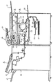
図1は本実施例における画像形成装置の概略構成模型図である。この画像形成装置は、転写式電子写真プロセスを用いたレーザビーム走査露光方式のプリンター部A、イメージリーダ部B、原稿給送装置C、フィニシャDを備えている。
(1) Example of Image Forming Apparatus FIG. 1 is a schematic configuration model diagram of an image forming apparatus in this embodiment. The image forming apparatus includes a laser beam scanning exposure type printer unit A, an image reader unit B, a document feeder C, and a finisher D using a transfer type electrophotographic process.
原稿給送装置Cは、セットされた原稿Oを先頭頁から順に1枚ずつ、湾曲したパスを介してイメージリーダ部Bのプラテンガラス21上に画像面下向きで給送し、プラテンガラス21上を左から右へ搬送し、排紙トレイ22へ排出する。このときイメージリーダ部Bのリーダスキャナユニット23はプラテンガラス21の下側において所定の定位置に保持された状態にあり、プラテンガラス21上を通過していく原稿の下向き面の画像を順次に流し読み方式で光電読み取りする。すなわち、リーダスキャナユニット23はプラテンガラス21上を通過していく原稿の下向き面をプラテンガラス21を介してランプ24の光で照明し、その照明光の原稿面からの反射光をミラー25、26、27、レンズ28を介してイメージセンサ29に導いて結像し、原稿画像を光電読み取りする。イメージセンサ29による原稿画像の光電読み取りは、原稿給送装置Cにより原稿をプラテンガラス21上に搬送して一旦停止させ、リーダスキャナユニット24、およびミラー26、27をプラテンガラス21の下面に沿って左から右へ移動させる、光学系移動方式で行うこともできる。
The document feeding device C feeds the set documents O one by one from the first page in order on the
イメージセンサ29により読み取った原稿画像の電気的信号は画像処理が施されて露光制御部(レーザスキャナ)30へ送られる。露光制御部30は画像処理が施された原稿画像の電気的信号に対応して変調されたレーザ光Lを出力する。
The electrical signal of the document image read by the
31は像担持体としてドラム型電子写真感光体(以下、感光ドラムと記す)であり、矢印の時計方向に所定の速度にて回転駆動される。感光ドラム1は回転状態において帯電器32により所定の極性・電位の一様帯電処理を受け、次いでその帯電処理面に上記の露光制御部30より出力されるレーザ光Lによる走査露光を受ける。これにより、感光ドラム31面に走査露光パターンに対応した静電潜像が形成される。そしてその静電潜像は現像器33によりトナー像として現像される。
感光ドラム31上に形成されたトナー像は、転写部34において、該転写部34に、第1または第2の給紙カセット36・37、手差し給紙部38、両面搬送パス39、のいずれかから給送された記録材(以下、シートと記す)Sに転写される。
The toner image formed on the
転写部34においてトナー像が転写されたシートSは感光ドラム31の面から分離されて定着装置40へ導入されてトナー像の定着処理を受ける。
The sheet S on which the toner image has been transferred in the transfer unit 34 is separated from the surface of the
シート分離後の感光ドラム1の面はクリーニング器35により転写残トナーや紙粉等の残留付着物の除去を受けて清掃されて繰り返して作像に供される。
After the sheet is separated, the surface of the
定着装置40を通過したシートは、片面画像形成モードの場合には、フラッパ41により一旦パス42に導き、シートの後端がフラッパ41を抜けた後にシートをスイッチバックさせてフラッパ41により排出ローラ43へ導く。これにより、シートは画像形成された面を下向きの状態(フェイスダウン)で排出ローラ43によりプリンター部AからフィニシャD側に排出される。
In the single-sided image forming mode, the sheet that has passed through the fixing
尚、手差し給紙部38からOHPシートなどの硬いシートを供給して画像形成を行うモードのときには、パス42に導くことなく、即ち、定着装置40を出た該シートをフラッパ41の上側を通過せて画像形成面を上向きの状態(フェイスアップ)で排出ローラ43から排出させる。
In the mode in which a hard sheet such as an OHP sheet is supplied from the manual
また、シートの両面に画像形成する両面画像モードの場合には、定着装置40を出た、第1面に画像形成したシートをフラッパ41の上側を通過せて排出ローラ43へ導き、該シートの後端がフラッパ41を抜けた直後に該シートをスイッチバックし、フラッパ41によりパス42から両面搬送パス39へ導く。そしてこの両面搬送パス39から再び転写部34へ表裏反転状態で給送することで、第2面に対するトナー像の転写を行なわせ、再び定着装置40に導入して第2面に対するトナー像の定着処理を行わせる。以後は上記した片面画像形成モードの場合と同様に排紙経路で両面画像形成済みのシートが排出ローラ43によりプリンター部AからフィニシャD側に排出される。
Further, in the double-sided image mode in which images are formed on both sides of the sheet, the sheet on which the image is formed on the first side that has exited the fixing
フィニッシャDではシフト処理、綴じ処理、穴あけ等の処理等を行う。また、フィニシャD上には、インサータEが設けられており、表紙、合紙等をフィニシャDに給送する。また整合板44はシフトソートなど記録材をずらして出力する場合に搬送方向と垂直な角度に移動してトレイ45上の奥又は手前にシートを排出する。
The finisher D performs processing such as shift processing, binding processing, and punching. An inserter E is provided on the finisher D, and feeds a cover sheet, a slip sheet, and the like to the finisher D. Further, the
(2)操作パネル
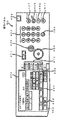
次に、操作パネル(操作部)について説明する。図2は画像形成装置に設けられた操作パネル60の構成を示す図である。400は複写開始を指示するコピースタートキーである。401は標準モードに戻すためのリセットキーである。402はガイダンス機能を使用するときに押下するガイダンスキーである。403は設定枚数等の数値を入力するテンキーである。404は数値をクリアするクリアキーである。405は連続コピー中にコピーを停止させるストップキーである。406はステープルモード、製本モードあるいは両面プリント設定等の各種モードの設定やプリンターの状態を表示する液晶表示部およびタッチパネルである。407は連続コピー中あるいはファックスやプリンターとして使用中に割り込んで緊急コピーをとるための割り込みキーである。408は個人別や部門別にコピー枚数を管理するための暗証キーである。409は画像形成装置本体の電源をON/OFFするためのソフトスイッチである。410は画像形成装置の機能を変更するときに使用する機能キーである。411は、オートカセットチェンジのON/OFFや省エネモードに入るまでの設定時間の変更など、予めユーザが項目を設定するユーザモードに入るためのユーザモードキーである。
(2) Operation Panel Next, the operation panel (operation unit) will be described. FIG. 2 is a diagram illustrating a configuration of the
450から452は記録材種類設定キー(画像形成する記録材種類を設定する記録材種類設定手段)であり、オーバーヘッドプロジェクタ用トランスペアレンシーフィルム(以下、OHPシートと記す)、厚紙、コート紙を設定するためのキーである。本実施形において厚紙は坪量210g以上の記録材とする。また、453は両面印刷を行うためのキーである。
(3)定着装置40
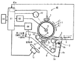
図3は定着装置40の概略構成模型図と制御系のブロック図である。この定着装置40
はベルト方式の熱圧定着装置である。
(3) Fixing
FIG. 3 is a schematic configuration model diagram of the fixing
Is a belt-type heat and pressure fixing device.
1は加熱源を有する定着回転体としての定着ローラである。この定着ローラ1は中空芯金3にシリコンゴム等の弾性層4を被覆し、更にその表層に離型層としてフッ素コート層5を被覆している。定着ローラ1の内部には、加熱源であるハロゲンランプ6が配置されている。この定着ローラ1はその両端部を軸受部材を介して定着装置の奥側と手前側の側板(不図示)間に回転自由に支持させて配設してある。7は定着ローラ1の表面温度を検知する検温手段としての第1のサーミスタであり、通紙域中央部に対応する定着ローラ表面部分に接触させて配設してある。
8は定着ローラ1の下側に配設したベルトユニットである。このベルトユニット8は、ユニット枠体8aと、このユニット枠体8aの奥側と手前側の側板8b(手前側の側板は不図示)間に互いに並行に回転自在に軸受支持させて配設した、ベルト張架部材としての3本のローラ13・14・15と、この3本のローラ13・14・15間に掛け回した無端状の加圧ベルト10と、加圧ベルト10の内側に配設した加圧パッド部材11と、加圧ベルト10の表面温度を検知する検温手段としての第2のサーミスタ2等のアセンブリである。そしてユニット枠体8aの奥側と手前側の側板8bをそれぞれ定着装置の奥側と手前側の側板に枢支することで、ベルトユニット8を定着装置の奥側と手前側の側板間において枢軸部8cを中心に定着ローラ1に対して上下揺動自由に支持させて配設してある。
A
加圧ベルト10はポリイミド等の耐熱性樹脂材料を無端ベルト状に成形したものである。
The
上記の3本のローラ13・14・15において、ローラ13は記録材入口側ローラ、ローラ14は加圧ベルト10に張りを与えるテンションローラ、ローラ15は記録材分離ローラである。
Of the three
第2のサーミスタ2は、記録材入口側ローラ13のベルト懸回部分において通紙域中央部に対応する加圧ベルト表面部分に接触させて配設してある。
The
加圧パッド部材11はアルミニウムをブロック状にしたもので、ユニット枠体8aの奥側と手前側の側板8bに設けたバネ受け座17との間に設けた押し上げバネ18により、記録材入口側ローラ13と分離ローラ15との間の加圧ベルト部分の内面に押圧接触状態にさせている。
The pressure pad member 11 is made of aluminum in a block shape, and is provided on the recording material inlet side by a push-up
64はベルトユニット8の上下揺動機構(定着ローラ1と加圧ベルト10を接離させる接離手段)であり、例えば、電磁ソレノイド−プランジャ機構、カム機構、レバー機構等で構成することができる。この上下揺動機構64は制御回路部(制御手段)61による制御で、ベルトユニット8を枢軸部8cを中心に定着ローラ1に対して上下揺動する。すなわち、
1)図3のように、ベルトユニット8を定着ローラ1に対して引き上げ方向に回動して、分離ローラ15を定着ローラ1に対して加圧ベルト10を挟ませて圧接させると共に、該分離ローラ15と記録材入口側ローラ13との間の加圧ベルト部分の外面を定着ローラ1の下面に接触状態にした第1位置と(着動作)
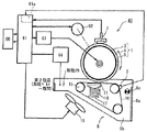
2)図4のように、ベルトユニット8を定着ローラ1から引き下げ方向に回動して、分離ローラ15と加圧ベルト10を定着ローラ1の下面から離間状態にした第2位置と(脱動作)
に切換え保持する。
1) As shown in FIG. 3, the
2) As shown in FIG. 4, the
Switch to and hold.
上記の枢軸部8cを中心に定着ローラ1に対して上下揺動自由のベルトユニット8と、このベルトユニット8の上下揺動機構64とで、定着ローラ1から加圧ベルト10を接触及び離間させる脱着機構を構成している。
The
図3のように、ベルトユニット8が第1位置に切換えられている状態においては、分離ローラ15が加圧ベルト10を挟んで定着ローラ1に圧接し、記録材入口側ローラ13と分離ローラ15との間の加圧ベルト部分の外面が定着ローラ1の下面に接触し、該加圧ベルト部分をベルト加圧パッド部材11がバネ18の圧縮反力で定着ローラ1の下面に圧接させた状態になることで、定着ローラ1と加圧ベルト10との間に幅広の定着ニップ部Nが形成された状態になる。
As shown in FIG. 3, when the
シートS上の未定着トナー像tの定着処理は上記のようにベルトユニット8が第1位置に切換えられて定着ローラ1と加圧ベルト10との間に定着ニップ部Nが形成された状態においてなされる。
The fixing process of the unfixed toner image t on the sheet S is performed in the state where the
すなわち、定着ローラ1は制御回路部61により制御される駆動装置62によって矢印の時計方向に所定の速度にて回転駆動される。加圧ベルト10は定着ローラ1の回転駆動に伴い矢印の反時計方向に従動回転する。定着ローラ1の加熱源であるハロゲンランプ6に電源部63から電力供給がなされて定着ローラ1が該ハロゲンランプ6の発熱により加熱される。その定着ローラ1の表面温度が第1のサーミスタ7により検知され、その検知温度が電気信号として制御回路部61の温度調節回路部61aに入力する。温度調節回路部61aは第1のサーミスタ7から入力する定着ローラ温度の電気信号が所定の定着温度に対応する電気信号に維持されるように電源部63からハロゲンランプ6への電力供給を制御して定着ローラ1の表面を温度調節する。
That is, the fixing
定着ローラ1が回転駆動され、それに伴い加圧ベルト10も従動回転し、また定着ローラ1がハロゲンランプ6により加熱され、所定の定着温度に温調された状態において、ベルトユニット8の記録材入口側ローラ13側から定着ニップ部Nに未定着トナー像を担持したシートSが導入されて定着ニップ部Nを挟持搬送されていく。この挟持搬送過程でシートSの未定着トナー像面が定着ローラ1の表面に密着してトナー像が定着ローラ1の熱で加熱され、シートSの面に加熱加圧定着される。シートSは定着ニップ部Nのシート出口部において定着ローラ1の弾性層4に対する分離ローラの食い込み(進入)により定着ローラ1の表面より分離されて排出搬送されていく。
When the fixing
加圧ベルト10はその表面温度が第2のサーミスタ2で検知され、その検知温度が電気信号として制御回路部61の温度調節回路部61aに入力する。
The surface temperature of the
(4)定着制御
図5〜図7を用いて本発明を特徴付ける加圧ベルト10の温度による定着制御に関して説明する。以下の定着制御は制御手段である制御回路部61が行う。
(4) Fixing Control Fixing control based on the temperature of the
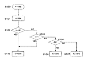
1)図5のフローチャートはジョブに使用する用紙種類によって定着制御基準となる所定温度Taを決定するためのフローチャートである。 1) The flowchart of FIG. 5 is a flowchart for determining a predetermined temperature Ta that is a fixing control reference according to the type of paper used for a job.
ステップS100で、操作パネル60上の記録材種類設定キーである、OHPシート選択キー450、厚紙選択キー451、コート紙キー452のいずれかでジョブ(画像形成処理)で使用用紙種類を設定する。S101ではコピースタートキー400が押圧されることでジョブ開始とする。まず、S102でコート紙が設定されているかどうかを判定する。コート紙が設定されていない場合はS103へと移る。コート紙が設定されている場合はS105にて定着制御基準となる所定温度Taを125℃と決定する。S103ではOHPシートが設定されているいかどうかを判定する。設定されていなければS104へと移り、設定されている場合はS105にて所定温度Taを125℃と決定する。S104では厚紙が設定されているかどうかを判定する。設定されていなければ、使用用紙種類が普通紙または薄紙であると判断して、S107へ移り所定温度Taを135℃と決定する。設定されている場合はS106にて所定温度Taを130℃と決定する。所定温度Taを決定したらそれぞれS400へ移る。
In step S100, the used paper type is set in the job (image forming process) by any of the OHP
各紙種についての所定温度Taとは、それぞれ、その紙種を用いたジョブにおける加圧ベルト10についての、画像不良・搬送不良を生じさせない昇温許容上限温度である。定着ローラの温調温度すなわち定着温度Tnとの関係において、上記の所定温度Taは定着温度Tnよりも低い設定にされる。
The predetermined temperature Ta for each paper type is a temperature rise allowable upper limit temperature that does not cause an image defect and a conveyance defect for the
具体例として、各紙種を用いたジョブにおける設定定着温度Tnを下表に示した。普通紙と薄紙で所定温度Taの変更はしない。また、定着温度Tnに関しても本例では用紙ごとに変更する様な制御はしない。 As a specific example, the set fixing temperature Tn in a job using each paper type is shown in the table below. The predetermined temperature Ta is not changed between plain paper and thin paper. In addition, the fixing temperature Tn is not controlled to be changed for each sheet in this example.
コート紙・OHP 厚 紙 普通紙 薄 紙
定着温度Tn 160℃ 160℃ 160℃ 160℃
所定温度Ta 125℃ 130℃ 135℃ 135℃
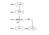
2)図6のフローチャートは印刷動作モードによって定着制御基準となる所定温度Taを決定するためのフローチャートである。
Coated paper / OHP Thick paper Plain paper Thin paper Fixing temperature Tn 160 ° C 160 ° C 160 ° C 160 ° C
Predetermined temperature Ta 125 ° C 130 ° C 135 ° C 135 ° C
2) The flowchart of FIG. 6 is a flowchart for determining a predetermined temperature Ta that serves as a fixing control reference according to the printing operation mode.
ステップS200でキー453にてジョブの印刷動作モードを設定する。S201ではコピースタートキーを押圧されることでジョブ開始とする。S202で両面印刷モードが設定されているかどうかを判定する。両面印刷モードが設定されていない場合はS204へと移り所定温度Taを135℃とする。両面印刷モードが設定されている場合はS203にて所定温度Taを125℃とする。所定温度Taを決定したらそれぞれS400へ移る。 In step S200, the print operation mode of the job is set with the key 453. In S201, the job is started by pressing the copy start key. In S202, it is determined whether or not the duplex printing mode is set. If the duplex printing mode is not set, the process proceeds to S204 and the predetermined temperature Ta is set to 135 ° C. If the duplex printing mode is set, the predetermined temperature Ta is set to 125 ° C. in S203. When the predetermined temperature Ta is determined, the process proceeds to S400.
上記において、両面印刷モードが設定されていない場合の上記所定温度Ta−135℃は使用記録材が普通紙(または薄紙)の場合である。コート紙・OHP、厚紙が指定されている場合はそれぞれ所定温度Ta−125℃、所定温度Ta−130℃に設定される。 In the above description, the predetermined temperature Ta-135 ° C. when the duplex printing mode is not set is the case where the recording material used is plain paper (or thin paper). When coated paper / OHP and cardboard are designated, the predetermined temperature Ta-125 ° C. and the predetermined temperature Ta-130 ° C. are set, respectively.
また、両面印刷モードが設定されている場合の上記所定温度Ta−125℃の場合も、使用記録材は普通紙(または薄紙)である。 The recording material used is also plain paper (or thin paper) when the predetermined temperature Ta-125 ° C. when the duplex printing mode is set.
記録材の第1面に対する画像形成時も、第2面に対する画像形成時の所定温度Ta−125℃の設定である。本例では、制御的にこれから定着する用紙が両面印刷の表面なのか、裏面なのかによって所定温度Taを変えることはしていない。 Even when an image is formed on the first surface of the recording material, the predetermined temperature Ta-125 ° C. is set when the image is formed on the second surface. In this example, the predetermined temperature Ta is not changed depending on whether the sheet to be fixed in the control is the front side or the back side of double-sided printing.
「両面印刷+コート紙または厚紙」の場合の所定温度Taは本例の場合は片面印刷時の所定温度Taと同じにしている。両面印刷時におけるフローチャートは所定温度Taが紙種だけでなく両面印刷時においても変わる事を示す。 The predetermined temperature Ta for “double-sided printing + coated paper or cardboard” is the same as the predetermined temperature Ta for single-sided printing in this example. The flowchart at the time of duplex printing shows that the predetermined temperature Ta changes not only at the paper type but also at the time of duplex printing.
「両面印刷モードが設定されている場合」と、「両面印刷モードが設定されていない場合」とで、所定温度Taを「135℃」と「125℃」とに高低違えるのは、基本的にはトナーが裏面にある場合と無い場合で温度が違うからである。 Basically, the predetermined temperature Ta is different between “135 ° C.” and “125 ° C.” between “when the duplex printing mode is set” and “when the duplex printing mode is not set”. This is because the temperature differs depending on whether the toner is on the back surface or not.
両面印刷時の裏面を定着する場合、用紙の裏側(表面)には既に定着されたトナーがある。この場合、所定温度Taが高すぎると既に定着してある裏側のトナーの再融解が起こる。この再融解において何が問題になるかと言うと、ベルトの材質による部分もあるが、基本的には再融解トナーがベルトに付着し用紙が剥離しない可能性が高まる。勿論、画像不良が発生する可能性もある。このような自体を避けるために片面時と両面時において所定温度Taに温度差を設けている。 When fixing the back side during duplex printing, there is already fixed toner on the back side (front side) of the paper. In this case, if the predetermined temperature Ta is too high, re-melting of the toner on the back side already fixed occurs. What is a problem in this remelting is partly due to the material of the belt, but basically the possibility that the remelted toner adheres to the belt and the paper does not peel off increases. Of course, image defects may occur. In order to avoid such a situation, a temperature difference is provided for the predetermined temperature Ta between one side and both sides.
本実施例の用紙種類及びに印刷動作モードは定着制御基準となる所定温度Taの値を決定することが目的であり本発明の範囲を限定するのもではない。 The paper type and the printing operation mode of the present embodiment are intended to determine the value of the predetermined temperature Ta serving as a fixing control reference, and do not limit the scope of the present invention.
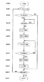
3)図7のフローチャートを用いて加圧ベルト10の温度によるジョブ中の加圧ベルト10の脱着制御について説明する。
3) Desorption control of the
ステップS400では、印字動作を開始する。加圧ベルト10の温度T1を第2のサーミスタ8から読み出す。S402では加圧ベルト温度T1の値と、図5のS200からS207にて決定した定着制御基準となる所定温度Taを比較する。加圧ベルト温度T1が所定温度Taよりも小さい場合はS409へと移り、大きい場合はS403にいく。S403では現在定着処理中を判断し、定着処理が終了するのを待ちS404へと移る。S304では、ジョブを一時停止をしS405にて加圧ベルト10の脱動作を行う。S406では、加圧ベルト10の温度T1を第2のサーミスタ8から再び読み出す。S407にて加圧ベルト温度T1が所定温度Taよりも大きい場合は、S406に戻り所定温度差Taよりも小さくなるのを待つ。この間、加圧ベルト10を冷却するためにファン19などの冷却手段を有し、これを用いて加圧ベルト10を冷却してもよいことは言うまでもない。所定温度Taよりも加圧ベルト温度T1が小さくなればS408にて加圧ベルト10の着動作を行い、S409にてジョブを再開する。S410で全ての印字処理が終了したかを判定し終了していなければS401へと戻り、終了していればS411にて終了する。
In step S400, the printing operation is started. The
以上のように、加圧ベルト10をジョブ中であっても脱動作することにより、定着ローラ1と加圧ベルト10の温度差を保つことができる。
As described above, the temperature difference between the fixing
(5)その他
1)ベルト定着における回転体としての定着ローラ1の加熱手段は実施例のような内部加熱方式に限られず、外部加熱方式、内部加熱・外部加熱併用方式とすることもできる。また電磁誘導加熱方式により定着ローラ自体を発熱させる構成にすることもできる。
(5) Others 1) The heating means of the fixing
2)定着ローラ1から加圧ベルト10を接触及び離間させる脱着機構は実施例の構成に限られず、任意に構成することができる。
2) The detaching mechanism for contacting and separating the
3)ベルト冷却手段も、ファン19にか切られず、その他、例えば、ベルトに接触して脱熱する放熱フィンやヒートパイプ部材等にすることもできる。
3) The belt cooling means is not cut by the
4)記録材に未定着トナー像を形成する画像形成手段は、電子写真、静電記録、磁気記録等の各種の作像原理・プロセセスのものにすることができ、転写方式に限られず、直接方式で記録材上に未定着トナー像を形成担持させるものであってもよい。カラーあるいは多色画像形成手段であっても勿論よい。 4) Image forming means for forming an unfixed toner image on a recording material can be of various image forming principles and processes such as electrophotography, electrostatic recording, magnetic recording, etc. An unfixed toner image may be formed and supported on a recording material by a method. Of course, it may be a color or multicolor image forming means.
5)上記の実施例においては、通紙使用する記録材の紙種を記録材紙種設定手段450〜452で手動設定(該手段による設定がなければ、普通紙または薄紙の設定)しているが、通紙された記録材の紙種を自動的に検知する紙種自動検知手段を配設して自動設定する装置構成にすることもできる。 5) In the above embodiment, the paper type of the recording material to be used is manually set by the recording material paper type setting means 450 to 452 (if there is no setting by the means, setting of plain paper or thin paper). However, it is also possible to adopt an apparatus configuration in which paper type automatic detection means for automatically detecting the paper type of the recording material that has been passed is provided and automatically set.
1...定着ローラ、6...ハロゲンランプ、7...サーミスタ、10..加圧ベルト、11..加圧パッド部材、19...加圧ベルト冷却ファン、61...制御回路部、450...OHPシート設定キー、451...厚紙設定キー、452...コート紙設定キー、453...両面印刷設定キー 1. . . Fixing roller, 6. . . 6. Halogen lamp, . . Thermistor, 10. . 10. pressure belt, . Pressure pad member, 19. . . Pressure belt cooling fan, 61. . . Control circuit section, 450. . . OHP sheet setting key, 451. . . Thick paper setting key 452. . . Coated paper setting key, 453. . . Duplex printing setting key
Claims (4)
前記ベルトの温度が所定温度以上となった場合、定着動作を中断して前記定着回転体と前記ベルトを離間させることを特徴とする定着装置。 A fixing rotator heated by a heat source, a rotatable belt for nipping and conveying a recording material carrying a toner image between the fixing rotator, a detecting means for detecting the temperature of the belt, and the fixing rotation A fixing device having contact and separation means for contacting and separating the belt and the belt;
When the temperature of the belt becomes equal to or higher than a predetermined temperature, the fixing operation is interrupted and the fixing rotating body and the belt are separated from each other.
Priority Applications (4)
| Application Number | Priority Date | Filing Date | Title |
|---|---|---|---|
| JP2004105244A JP2005292333A (en) | 2004-03-31 | 2004-03-31 | Fixing device |
| US11/085,549 US7280777B2 (en) | 2004-03-31 | 2005-03-22 | Image forming apparatus with fixing control based on recording material type |
| CNA2005100588743A CN1677273A (en) | 2004-03-31 | 2005-03-30 | Image forming apparatus |
| US11/774,139 US7421220B2 (en) | 2004-03-31 | 2007-07-06 | Image forming apparatus with fixing control based on recording material type |
Applications Claiming Priority (1)
| Application Number | Priority Date | Filing Date | Title |
|---|---|---|---|
| JP2004105244A JP2005292333A (en) | 2004-03-31 | 2004-03-31 | Fixing device |
Publications (2)
| Publication Number | Publication Date |
|---|---|
| JP2005292333A true JP2005292333A (en) | 2005-10-20 |
| JP2005292333A5 JP2005292333A5 (en) | 2007-05-10 |
Family
ID=35049836
Family Applications (1)
| Application Number | Title | Priority Date | Filing Date |
|---|---|---|---|
| JP2004105244A Pending JP2005292333A (en) | 2004-03-31 | 2004-03-31 | Fixing device |
Country Status (3)
| Country | Link |
|---|---|
| US (2) | US7280777B2 (en) |
| JP (1) | JP2005292333A (en) |
| CN (1) | CN1677273A (en) |
Cited By (6)
| Publication number | Priority date | Publication date | Assignee | Title |
|---|---|---|---|---|
| JP2007108695A (en) * | 2005-09-12 | 2007-04-26 | Canon Inc | Image forming apparatus |
| JP2008145451A (en) * | 2006-12-05 | 2008-06-26 | Canon Inc | Fixing apparatus and image forming apparatus |
| JP2012098494A (en) * | 2010-11-02 | 2012-05-24 | Canon Inc | Image forming device |
| CN102854781A (en) * | 2011-06-28 | 2013-01-02 | 株式会社东芝 | Fuser, image forming apparatus, and image forming method |
| JP2013041191A (en) * | 2011-08-19 | 2013-02-28 | Ricoh Co Ltd | Fixing device, and image forming apparatus |
| JP2017032897A (en) * | 2015-08-05 | 2017-02-09 | キヤノン株式会社 | Image forming apparatus |
Families Citing this family (14)
| Publication number | Priority date | Publication date | Assignee | Title |
|---|---|---|---|---|
| JP4732088B2 (en) * | 2005-09-13 | 2011-07-27 | キヤノン株式会社 | Image heating device |
| JP4402508B2 (en) * | 2004-04-28 | 2010-01-20 | キヤノン株式会社 | Image forming apparatus |
| US7433620B2 (en) * | 2004-07-13 | 2008-10-07 | Canon Kabushiki Kaisha | Image forming apparatus with controlled electric power supply to heating member |
| JP4194540B2 (en) * | 2004-07-27 | 2008-12-10 | キヤノン株式会社 | Image forming apparatus |
| US7433640B2 (en) * | 2005-03-15 | 2008-10-07 | Ricoh Printing Systems, Ltd. | Fixing apparatus and image forming apparatus including heating member |
| US7761044B2 (en) | 2005-08-24 | 2010-07-20 | Ricoh Company, Ltd. | Fixing device and image forming apparatus using the same |
| US7522870B2 (en) * | 2005-09-13 | 2009-04-21 | Canon Kabushiki Kaisha | Image heating apparatus with control means for controlling heating rotatable member in accordance with belt operation |
| JP4994726B2 (en) * | 2006-07-10 | 2012-08-08 | キヤノン株式会社 | Image forming apparatus |
| JP2008020575A (en) * | 2006-07-12 | 2008-01-31 | Ricoh Co Ltd | Fixing device, image forming apparatus |
| KR20080072219A (en) * | 2007-02-01 | 2008-08-06 | 삼성전자주식회사 | Image Forming Device |
| US8041245B2 (en) * | 2009-08-31 | 2011-10-18 | Xerox Corporation | Apparatuses useful in printing and methods of controlling the temperature of surfaces in apparatuses useful in printing |
| JP5482310B2 (en) * | 2010-03-09 | 2014-05-07 | 株式会社リコー | Fixing apparatus and image forming apparatus |
| JP5708084B2 (en) * | 2011-03-17 | 2015-04-30 | 株式会社リコー | Fixing device and image forming apparatus having the same |
| WO2013070833A1 (en) | 2011-11-08 | 2013-05-16 | Taishita LLC | Portable multiuse projector with fiber optic projection |
Citations (5)
| Publication number | Priority date | Publication date | Assignee | Title |
|---|---|---|---|---|
| JPS60142375A (en) * | 1983-12-29 | 1985-07-27 | Canon Inc | Double-sided image forming device |
| JPH11194647A (en) * | 1998-01-07 | 1999-07-21 | Fuji Xerox Co Ltd | Fixing device |
| JPH11202679A (en) * | 1998-01-16 | 1999-07-30 | Sharp Corp | Fixing method and fixing device |
| JP2001201979A (en) * | 2000-01-20 | 2001-07-27 | Fuji Xerox Co Ltd | Image fixing device |
| JP2002082567A (en) * | 2000-06-21 | 2002-03-22 | Ricoh Co Ltd | Fixing device and image forming device |
Family Cites Families (17)
| Publication number | Priority date | Publication date | Assignee | Title |
|---|---|---|---|---|
| US4796035A (en) | 1984-11-30 | 1989-01-03 | Canon Kabushiki Kaisha | Image recording apparatus with improved system for feeding and exhausting recording sheets |
| JPS61132972A (en) | 1984-12-03 | 1986-06-20 | Konishiroku Photo Ind Co Ltd | Fixing device |
| JPH01195483A (en) * | 1988-01-30 | 1989-08-07 | Toshiba Corp | Electronic copying machine |
| JPH01279278A (en) | 1988-05-06 | 1989-11-09 | Ricoh Co Ltd | Fusing device |
| JPH03288171A (en) | 1990-04-04 | 1991-12-18 | Matsushita Electric Ind Co Ltd | Multicolor image recording device |
| JP3230948B2 (en) | 1994-10-03 | 2001-11-19 | キヤノン株式会社 | Image forming device |
| JPH10333463A (en) * | 1997-06-04 | 1998-12-18 | Minolta Co Ltd | Fixing device |
| JP2000118783A (en) | 1998-10-16 | 2000-04-25 | Canon Inc | Image forming device |
| US6311039B1 (en) | 1998-10-26 | 2001-10-30 | Canon Kabushiki Kaisha | Sheet conveying apparatus and image forming apparatus provided with the same |
| JP2000235319A (en) | 1999-02-16 | 2000-08-29 | Sharp Corp | Developer fixing device and fixing method |
| US6393232B1 (en) | 1999-07-30 | 2002-05-21 | Canon Kabushiki Kaisha | Image forming apparatus capable of selecting discharge means according to material selection |
| US6650863B2 (en) * | 2001-02-26 | 2003-11-18 | Konica Corporation | Fixing unit and image forming apparatus |
| JP2004020751A (en) | 2002-06-13 | 2004-01-22 | Sharp Corp | Heating device and heating method |
| JP2004198823A (en) | 2002-12-19 | 2004-07-15 | Fuji Xerox Co Ltd | Fixing device |
| US7110689B2 (en) | 2003-05-01 | 2006-09-19 | Canon Kabushiki Kaisha | Image heating apparatus with mechanism to prevent twining recording material |
| JP2004341177A (en) | 2003-05-15 | 2004-12-02 | Canon Inc | Fixing device |
| US7050751B2 (en) | 2003-07-28 | 2006-05-23 | Canon Kabushiki Kaisha | Image forming system with temporary storage trays between sheet storage units and image forming apparatus |
-
2004
- 2004-03-31 JP JP2004105244A patent/JP2005292333A/en active Pending
-
2005
- 2005-03-22 US US11/085,549 patent/US7280777B2/en not_active Expired - Fee Related
- 2005-03-30 CN CNA2005100588743A patent/CN1677273A/en active Pending
-
2007
- 2007-07-06 US US11/774,139 patent/US7421220B2/en not_active Expired - Fee Related
Patent Citations (5)
| Publication number | Priority date | Publication date | Assignee | Title |
|---|---|---|---|---|
| JPS60142375A (en) * | 1983-12-29 | 1985-07-27 | Canon Inc | Double-sided image forming device |
| JPH11194647A (en) * | 1998-01-07 | 1999-07-21 | Fuji Xerox Co Ltd | Fixing device |
| JPH11202679A (en) * | 1998-01-16 | 1999-07-30 | Sharp Corp | Fixing method and fixing device |
| JP2001201979A (en) * | 2000-01-20 | 2001-07-27 | Fuji Xerox Co Ltd | Image fixing device |
| JP2002082567A (en) * | 2000-06-21 | 2002-03-22 | Ricoh Co Ltd | Fixing device and image forming device |
Cited By (7)
| Publication number | Priority date | Publication date | Assignee | Title |
|---|---|---|---|---|
| JP2007108695A (en) * | 2005-09-12 | 2007-04-26 | Canon Inc | Image forming apparatus |
| JP2008145451A (en) * | 2006-12-05 | 2008-06-26 | Canon Inc | Fixing apparatus and image forming apparatus |
| JP2012098494A (en) * | 2010-11-02 | 2012-05-24 | Canon Inc | Image forming device |
| US8712271B2 (en) | 2010-11-02 | 2014-04-29 | Canon Kabushiki Kaisha | Image forming apparatus |
| CN102854781A (en) * | 2011-06-28 | 2013-01-02 | 株式会社东芝 | Fuser, image forming apparatus, and image forming method |
| JP2013041191A (en) * | 2011-08-19 | 2013-02-28 | Ricoh Co Ltd | Fixing device, and image forming apparatus |
| JP2017032897A (en) * | 2015-08-05 | 2017-02-09 | キヤノン株式会社 | Image forming apparatus |
Also Published As
| Publication number | Publication date |
|---|---|
| US20050220467A1 (en) | 2005-10-06 |
| US7421220B2 (en) | 2008-09-02 |
| US20080013977A1 (en) | 2008-01-17 |
| US7280777B2 (en) | 2007-10-09 |
| CN1677273A (en) | 2005-10-05 |
Similar Documents
| Publication | Publication Date | Title |
|---|---|---|
| US7421220B2 (en) | Image forming apparatus with fixing control based on recording material type | |
| JP5587087B2 (en) | Fixing device | |
| JP5173464B2 (en) | Image forming apparatus | |
| JP3450623B2 (en) | Image forming device | |
| US8116654B2 (en) | Image heating apparatus | |
| JP7313835B2 (en) | Fixing device and image forming device | |
| JP6272134B2 (en) | Fixing device | |
| US7283759B2 (en) | Image forming apparatus with heating member control in accordance with type of recording material | |
| JP3629354B2 (en) | Image forming apparatus | |
| JP2025028154A (en) | Fixing device and image forming apparatus | |
| US20240295844A1 (en) | Image forming apparatus | |
| JP2004020689A (en) | Image forming device | |
| JP2005140994A (en) | Image forming apparatus | |
| JP2009175601A (en) | Image forming apparatus | |
| JP4649226B2 (en) | Image forming apparatus | |
| JP2005189372A (en) | Image forming apparatus | |
| JP5358122B2 (en) | Fixing apparatus and image forming apparatus | |
| JP4677220B2 (en) | Image heating apparatus and image forming apparatus | |
| JP4898258B2 (en) | Image forming apparatus | |
| JP2015184534A (en) | Image forming apparatus and fixing device | |
| JPH087506B2 (en) | Image heating fixing device | |
| JP2011180216A (en) | Image forming apparatus | |
| JP2004184696A (en) | Image forming device | |
| JP2010139954A (en) | Image forming apparatus | |
| JP3605069B2 (en) | Image forming device |
Legal Events
| Date | Code | Title | Description |
|---|---|---|---|
| A521 | Written amendment |
Free format text: JAPANESE INTERMEDIATE CODE: A523 Effective date: 20070312 |
|
| A621 | Written request for application examination |
Free format text: JAPANESE INTERMEDIATE CODE: A621 Effective date: 20070312 |
|
| A977 | Report on retrieval |
Free format text: JAPANESE INTERMEDIATE CODE: A971007 Effective date: 20091015 |
|
| A131 | Notification of reasons for refusal |
Free format text: JAPANESE INTERMEDIATE CODE: A131 Effective date: 20091020 |
|
| A521 | Written amendment |
Free format text: JAPANESE INTERMEDIATE CODE: A523 Effective date: 20091130 |
|
| A131 | Notification of reasons for refusal |
Free format text: JAPANESE INTERMEDIATE CODE: A131 Effective date: 20100216 |
|
| A521 | Written amendment |
Free format text: JAPANESE INTERMEDIATE CODE: A523 Effective date: 20100416 |
|
| A131 | Notification of reasons for refusal |
Free format text: JAPANESE INTERMEDIATE CODE: A131 Effective date: 20100622 |
|
| A521 | Written amendment |
Free format text: JAPANESE INTERMEDIATE CODE: A523 Effective date: 20100820 |
|
| A02 | Decision of refusal |
Free format text: JAPANESE INTERMEDIATE CODE: A02 Effective date: 20100928 |