JP2005292301A - Developing device, process cartridge, image forming apparatus - Google Patents
Developing device, process cartridge, image forming apparatus Download PDFInfo
- Publication number
- JP2005292301A JP2005292301A JP2004104469A JP2004104469A JP2005292301A JP 2005292301 A JP2005292301 A JP 2005292301A JP 2004104469 A JP2004104469 A JP 2004104469A JP 2004104469 A JP2004104469 A JP 2004104469A JP 2005292301 A JP2005292301 A JP 2005292301A
- Authority
- JP
- Japan
- Prior art keywords
- developing device
- pumping
- developing roller
- developing
- screw
- Prior art date
- Legal status (The legal status is an assumption and is not a legal conclusion. Google has not performed a legal analysis and makes no representation as to the accuracy of the status listed.)
- Pending
Links
Images

Landscapes
- Dry Development In Electrophotography (AREA)
- Developing Agents For Electrophotography (AREA)
- Magnetic Brush Developing In Electrophotography (AREA)
Abstract
【課題】 攪拌スクリューのピッチによる濃度ムラのない優れた画質を得ることのできる現像装置を提供する。
【解決手段】 非磁性スリーブの内部に磁石ローラを配置した現像ローラ32と、スクリュー状攪拌部材33を有する現像装置3において、現像ローラ32とスクリュー状攪拌部材33aの間に磁性体からなる汲み上げ補助部材35を配置する。現像ローラ32から発生する磁束は磁性体である汲み上げ補助部材35に集中するため、この補助部材位置では、補助部材がない場合に比べて磁気力が強くなり、その結果汲み上げ性が向上する。
【選択図】 図1PROBLEM TO BE SOLVED: To provide a developing device capable of obtaining an excellent image quality without density unevenness due to a pitch of a stirring screw.
In a developing device 3 having a developing roller 32 having a magnet roller disposed inside a non-magnetic sleeve and a screw-like stirring member 33, a pumping assist made of a magnetic material is provided between the developing roller 32 and the screw-like stirring member 33a. The member 35 is disposed. Since the magnetic flux generated from the developing roller 32 is concentrated on the pumping assisting member 35 that is a magnetic material, the magnetic force becomes stronger at the position of the assisting member than in the case where there is no assisting member, resulting in improved pumping performance.
[Selection] Figure 1
Description
本発明は、像担持体上に形成された潜像を可視像化する現像装置に関し、さらに詳しく言えばスクリュー状攪拌部材を備える現像装置に関するものである。 The present invention relates to a developing device that visualizes a latent image formed on an image carrier, and more particularly to a developing device including a screw-like stirring member.
電子写真その他の、粉体トナーを用いた画像形成方法において、一成分または二成分現像剤を用いた磁気ブラシ現像は周知であり、複写機、プリンタ、ファクシミリ等の画像形成装置において広く利用されている。 In electrophotographic and other image forming methods using powder toner, magnetic brush development using a one-component or two-component developer is well known and widely used in image forming apparatuses such as copiers, printers, and facsimiles. Yes.
磁気ブラシ現像では、現像剤担持体の表面に現像剤を搬送し、現像剤をブラシ状(磁気ブラシ)に保持させ、静電潜像が形成された像担持体と電気的バイアスが印加されたスリーブとの間の電界によってトナーが潜像面に選択的に付着することにより、現像が行われる。 In magnetic brush development, the developer is transported to the surface of the developer carrier, the developer is held in a brush shape (magnetic brush), and an electric bias is applied to the image carrier on which the electrostatic latent image is formed. The toner is selectively attached to the latent image surface by the electric field between the sleeve and the development.
上記現像剤担持体は、通常、円筒状のスリーブ(現像スリーブ)として構成され、このスリーブ表面に現像剤の穂立ちを生じさせるように磁界を形成する磁石体(磁石ローラ)をスリーブ内部に備えている。穂立ちの際、キャリアが磁石ローラで生じる磁力線に沿うようにスリーブ上に穂立ちすると共に、この穂立ちに係るキャリアに対して帯電トナーが付着されている。上記スリーブと磁石ローラの少なくとも一方が動くことでスリーブ表面に穂立ちを起こした現像剤が移動するようになっている。なお、以下の説明では、スリーブ内部に磁石ローラを備えた現像剤担持体の全体を指して現像ローラと呼ぶ。 The developer carrier is usually configured as a cylindrical sleeve (developing sleeve), and a magnet body (magnet roller) that forms a magnetic field so as to cause the developer to rise on the sleeve surface is provided inside the sleeve. ing. At the time of spike, the carrier is spiked on the sleeve so as to follow the lines of magnetic force generated by the magnet roller, and charged toner is attached to the carrier related to the spike. When at least one of the sleeve and the magnet roller is moved, the developer having raised the sleeve surface is moved. In the following description, the entire developer carrying member provided with a magnet roller inside the sleeve is referred to as a developing roller.
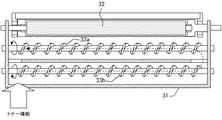
そして、上記のような現像装置では、多くの場合、現像器のケーシング内で現像剤を攪拌する目的でスクリュー状の攪拌部材(攪拌スクリュー)を備えている。ここで、2軸の攪拌スクリューを備えた現像装置の一例における、現像装置内の現像剤の動きについて説明する。 In many cases, the developing device as described above is provided with a screw-like stirring member (stirring screw) for the purpose of stirring the developer in the casing of the developing device. Here, the movement of the developer in the developing device in an example of the developing device including the biaxial stirring screw will be described.
図5に示すように、現像器のケーシング31内には、現像ローラ32と平行に2軸の(2本の)攪拌スクリュー33a,33bが配設されている。現像ローラ32から遠い方の攪拌スクリュー33bの軸方向の端部から補給されたトナーは、スクリューにより搬送されながら現像剤と攪拌され、図に破線の矢印で示す如く軸方向に送られる。現像ローラ側の攪拌スクリュー33aに受け渡された現像剤は、現像ローラ32の磁力によってスリーブ表面に汲み上げられ、層厚規制部材によって現像剤量を均一化した後に感光体ドラムと対向する現像領域へと搬送される。
As shown in FIG. 5, biaxial (two)
現像装置の構成には、図6に示すような現像ローラ32の上側または横側に層厚規制ブレード34を配置し、現像ローラ32の下側で現像装置内に剤離れを行なう形態と、図7に示すように、現像ローラ32の下側に層厚規制ブレード34を配置し、現像ローラ32の上側で現像装置内に剤離れを行なう形態があり、感光体ドラム1他のユニットのレイアウトによって使い分けられている。
In the configuration of the developing device, a layer thickness regulating
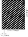
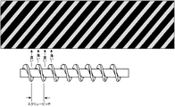
このような構成の現像装置を備える画像形成装置において、写真など面積率の比較的大きい画像をプリントアウトすると、テキスト文章など面積率の比較的小さい画像に比べ、濃度ムラが目立つことがある。面積率の大きな単色画像では、通紙方向に対して斜め方向の濃度ムラ(一例を図8に示す)が縞状に発生して画像品質を低下させる。また、面積率の大きなフルカラー画像では、各色の濃度ムラが色相のズレとなって現われる。 In an image forming apparatus including the developing device having such a configuration, when an image having a relatively large area ratio such as a photograph is printed out, density unevenness may be more conspicuous than an image having a relatively small area ratio such as a text sentence. In a single-color image with a large area ratio, density unevenness (an example is shown in FIG. 8) in a diagonal direction with respect to the sheet passing direction occurs in a striped pattern, thereby reducing the image quality. Further, in a full color image with a large area ratio, density unevenness of each color appears as a hue shift.
一般的に市場においては、例えばデザイン系の職業において、このような大きな画像を取り扱うことがあり、縞状の濃度ムラによって商品価値を著しく低減させてしまう。 In general, in the market, for example, in design occupations, such a large image may be handled, and the product value is significantly reduced by striped density unevenness.
上述の濃度ムラは、図9に示すように、現像ユニット内のスクリューのピッチとムラのピッチが等しく、近年の高画質化を狙った磁性キャリアの小粒径化に伴い発生率が高く、また傾向として現像ローラの現像剤汲み上げ性が低い場合に発生しやすいことも判っている。これは、スクリュ上を移動する現像剤はスクリュの山で高く谷で低いため、汲み上げ性が不充分で谷部での現像剤汲み上げ量が少なくなりすぎると規制部材を通過する現像剤の量が少なかったり、現像剤量が少ないことによって規制部材での帯電不充分であることにより発生すると考えられている。 As shown in FIG. 9, the density unevenness described above is the same as the pitch of the screw in the developing unit and the unevenness pitch, and the incidence is high with the recent reduction in the particle diameter of the magnetic carrier aiming at high image quality. It has also been found that this tendency is likely to occur when the developer pumping ability of the developing roller is low. This is because the developer moving on the screw is high at the peak of the screw and low at the valley, so that the pumping performance is insufficient, and if the amount of developer pumped up at the valley is too small, the amount of developer passing through the regulating member will be small It is considered that this occurs due to insufficient charging or insufficient charging at the regulating member due to a small amount of developer.
濃度ムラの対策として、例えば特許文献1あるいは特許文献2には、現像ローラの磁気特性その他に工夫を施すことによってスクリューピッチムラを減少させることが提案されている。
As a countermeasure against density unevenness, for example,
しかしながら、上記特許文献1または特許文献2のように、現像ローラの磁気特性を変更して対応する構成の場合、一般的に層厚規制ブレード前の現像剤量を多くし、ブレードでの規制をきつくすることによってスクリューの凸凹の履歴を消そうとすることになる。この場合、層厚規制ブレードの部分で現像剤が受ける力が大きくなるため、現像剤の劣化が早くなって寿命が短くなってしまうという問題がある。
However, as in the case of
また、特許文献3に記載された現像装置はスクリュー寸法を規制することによりピッチムラの低減を狙ったものであるが、スクリューの凸凹の履歴を消すことはできないため、濃度ムラ防止の効果は充分ではない。 Further, the developing device described in Patent Document 3 aims to reduce pitch unevenness by regulating screw dimensions, but since the unevenness of the screw cannot be erased, the effect of preventing density unevenness is not sufficient. Absent.
本発明は、従来の攪拌スクリューを備えた現像装置における上述の問題を解決し、スクリューピッチムラのない優れた画質を得ることのできる現像装置を提供することを課題とする。 An object of the present invention is to solve the above-described problems in a developing device having a conventional stirring screw and to provide a developing device capable of obtaining an excellent image quality free from screw pitch unevenness.
前記の課題は、本発明により、非磁性スリーブの内部に磁石ローラを配置した現像ローラと、スクリュー状攪拌部材を有する現像装置において、前記現像ローラとスクリュー状攪拌部材の間に磁性体からなる汲み上げ補助部材を配置したことにより解決される。 According to the present invention, there is provided a developing device having a developing roller having a magnet roller disposed inside a non-magnetic sleeve and a screw-like stirring member, and pumping a magnetic material between the developing roller and the screw-like stirring member. This is solved by arranging the auxiliary member.
また、前記の課題を解決するため、本発明は、前記現像ローラの汲み上げ磁極が前記現像ローラの中心と前記攪拌部材を結ぶ線上の近傍にあり、かつ、前記汲み上げ補助部材が前記現像ローラの中心と前記攪拌部材を結ぶ線上の近傍にあることを提案する。 In order to solve the above problems, the present invention provides a pumping magnetic pole of the developing roller in the vicinity of a line connecting the center of the developing roller and the stirring member, and the pumping auxiliary member is a center of the developing roller. It is proposed to be in the vicinity of a line connecting the stirring member.
また、前記の課題を解決するため、本発明は、前記汲み上げ補助部材が回転駆動されることを提案する。
また、前記の課題を解決するため、本発明は、粒径20〜50μmの磁性キャリアを含む現像剤を用いることを提案する。
Moreover, in order to solve the said subject, this invention proposes that the said scooping auxiliary member is rotationally driven.
In order to solve the above problems, the present invention proposes to use a developer containing a magnetic carrier having a particle diameter of 20 to 50 μm.
また、前記の課題は、本発明により、請求項1〜4のいずれか1項に記載の現像装置を搭載するプロセスカートリッジであって、該現像装置と作像工程に必要な現像装置以外の少なくとも1つの機器とを一体的にユニット化し、画像形成装置本体に着脱可能に設けたプロセスカートリッジにより解決される。
Further, according to the present invention, there is provided a process cartridge including the developing device according to any one of
また、前記の課題は、本発明により、請求項1〜4のいずれか1項に記載の現像装置または請求項5に記載のプロセスカートリッジを備える画像形成装置により解決される。
Further, according to the present invention, the above problem is solved by an image forming apparatus including the developing device according to any one of
本発明の現像装置、プロセスカートリッジ、画像形成装置によれば、現像ローラとスクリュー状攪拌部材の間に磁性体からなる汲み上げ補助部材を配置したので、汲み上げ性が向上するとともに、攪拌スクリューのピッチによる濃度ムラを低減させることができ、優れた現像品質を得ることができる。 According to the developing device, the process cartridge, and the image forming apparatus of the present invention, the pumping assisting member made of a magnetic material is disposed between the developing roller and the screw-shaped stirring member. Density unevenness can be reduced, and excellent development quality can be obtained.
請求項2の構成により、現像ローラの汲み上げ磁極が前記現像ローラの中心と前記攪拌部材を結ぶ線上の近傍にあり、かつ、前記汲み上げ補助部材が前記現像ローラの中心と前記攪拌部材を結ぶ線上の近傍にあるので、現像剤の汲み上げ性がより向上し、また、補助部材を通過する現像剤が上流側と下流側で均等に近い状態となるため、攪拌性が高く、スクリューピッチによるムラがより均一化されやすい。
According to the configuration of
請求項3の構成により、汲み上げ補助部材が回転駆動されることで、現像剤の攪拌性がさらに向上し、スクリューピッチによるムラの防止効果が向上する。
請求項4の構成により、粒径20〜50μmの磁性キャリアを含む現像剤を用いるので、粒状度に優れた良好な画像を得ることができる。
According to the third aspect of the present invention, the pumping assisting member is rotationally driven, whereby the stirring property of the developer is further improved, and the effect of preventing unevenness due to the screw pitch is improved.
According to the fourth aspect of the present invention, since a developer containing a magnetic carrier having a particle size of 20 to 50 μm is used, a good image having excellent granularity can be obtained.
以下、本発明の実施の形態を図面に基づいて説明する。
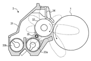
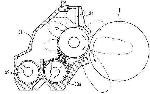
図1は、本発明に係る現像装置の一例を示す断面構成図である。この図に示す現像装置3は、現像ケーシング31内に2軸の攪拌スクリュー33a,33bを備えている。現像ローラ32は、内部に磁石ローラ(図示せず)を備えている。この現像ローラ32の上方には、層厚規制部材としての規制ブレード34が配置されている。現像ローラ32は、当該現像装置が装着される画像形成装置の像担持体である感光体ドラム1に近接配置されている。なお、図6,7で説明した現像装置と同等の部分には同じ符号を付している。
Hereinafter, embodiments of the present invention will be described with reference to the drawings.
FIG. 1 is a cross-sectional configuration diagram illustrating an example of a developing device according to the present invention. The developing device 3 shown in this figure includes a
さて、本例の現像装置3では、現像ローラ32と攪拌スクリュー33a(2本のスクリューのうち現像ローラ32側の攪拌スクリュー)の間に磁性体からなる汲み上げ補助部材35を設けている。現像ローラ32は、その汲み上げ磁極が現像ローラ32の中心と攪拌スクリュー33aを結ぶ線状の近傍となるように設定されている。また、汲み上げ補助部材35も現像ローラ32の中心と攪拌スクリュー33aを結ぶ線状の近傍に配置されている。したがって、汲み上げ補助部材35と現像ローラ32の汲み上げ極および攪拌スクリュー32aがほぼ直線状の配置となっている。
In the developing device 3 of this example, a pumping
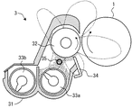
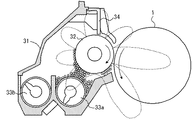
図2は、本発明に係る現像装置の別例を示す断面構成図である。この図に示す現像装置30は、層厚規制部材である規制ブレード34が現像ローラ32の下側に配置され、現像ローラ32の上側で現像装置内に剤離れを行なう形態であること以外は図1の現像装置3と同様である。また、図1の現像装置3と同等の部分には同じ符号を付してある。
FIG. 2 is a cross-sectional configuration diagram showing another example of the developing device according to the present invention. The developing device 30 shown in this figure is a configuration except that a
さて、本例の現像装置30でも、現像ローラ32と攪拌スクリュー33a(2本のスクリューのうち現像ローラ32側の攪拌スクリュー)の間に磁性体からなる汲み上げ補助部材35を設けている。現像ローラ32は、その汲み上げ磁極が現像ローラ32の中心と攪拌スクリュー33aを結ぶ線状の近傍となるように設定されている。また、汲み上げ補助部材35も現像ローラ32の中心と攪拌スクリュー33aを結ぶ線状の近傍に配置されている。したがって、汲み上げ補助部材35と現像ローラ32の汲み上げ極および攪拌スクリュー32aがほぼ直線状の配置となっている。
In the developing device 30 of this example, a pumping
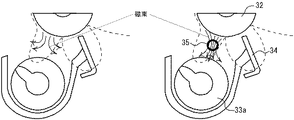
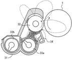
図1,2の現像装置3及び30における汲み上げ補助部材35の作用について、図3を参照して説明する。図3では図2の現像装置30の形態で説明する。なお、比較のために汲み上げ補助部材35を有さない場合を図3(a)に、汲み上げ補助部材35を設けた場合を図3(b)に並べて示してある。
The operation of the pumping
図3(b)に示すように、現像ローラ32から発生する磁束は磁性体である汲み上げ補助部材35に集中するため、この補助部材位置では、補助部材がない場合に比べて磁気力が強くなり、その結果汲み上げ性が向上する。
As shown in FIG. 3B, the magnetic flux generated from the developing
ところで、現像ローラの汲み上げ性を向上させようとして汲み上げ磁極を高くしすぎた(汲み上げ極の磁力を高くしすぎた)場合には、逆に谷部での汲み上げ量が多くなりすぎ、現像ローラに付着する現像剤量もスクリューピッチ形状となる(ムラが発生する)懸念もあるが、本発明による現像装置の場合は、汲み上げ補助部材35を設けたことにより汲み上げ性を向上させているため、現像剤は均一に現像ローラ32に付着する。したがって、攪拌スクリューのピッチによる濃度ムラを防止し、優れた画質を得ることができる。また、層厚規制ブレードでの現像剤規制をきつくすることもなく、現像剤の寿命を低減させる恐れもない。
By the way, if the pumping magnetic pole is made too high in order to improve the pumping performance of the developing roller (the magnetic force of the pumping pole is made too high), the pumping amount at the valley becomes too large, Although there is a concern that the amount of developer adhering may also have a screw pitch shape (unevenness is generated), in the case of the developing device according to the present invention, since the
また、装置構成上現像剤の上面と現像ローラの距離が遠い等で汲み上げ性が充分とはいえない場合、あるいは、トナーの消費に伴って現像剤の嵩が減少し汲み上げ性が充分とはいえない場合でも、上記のように汲み上げ補助部材35を設けたことにより、汲み上げ補助部材35に引き付けられた現像剤が補助部材のスクリュー側で分断されて補助部材を回り込み、現像ローラ側で合流する間に攪拌が行なわれるため、スクリューピッチによるムラが均一化され、均一な状態で現像ローラに付着する。よって、装置構成上あるいはトナー消費による汲み上げ性が充分でない場合でも、濃度ムラの防止に効果を得ることができる。
Further, when the distance between the upper surface of the developer and the developing roller is long due to the construction of the apparatus, the pumping performance is not sufficient, or the volume of the developer decreases as the toner is consumed, and the pumping performance is sufficient. Even when there is not, the
さらに、上記現像装置3及び30においては、汲み上げ補助部材35と現像ローラ32の汲み上げ極および攪拌スクリュー32aがほぼ直線状の配置であるため、現像剤の汲み上げ性をより向上させ、また、補助部材35を通過する(回り込む)現像剤が上流側と下流側(現像ローラ回転方向の上流側と下流側)で均等に近い状態となるため、攪拌性が高く、スクリューピッチによるムラがより均一化されやすい。
Further, in the developing devices 3 and 30, the pumping
なお、上記現像装置3及び30においては、汲み上げ補助部材35は固定配置であるが、汲み上げ補助部材35を回転駆動するように構成しても良い。汲み上げ補助部材35を回転させた場合、汲み上げ補助部材35に磁気的に吸着した現像剤の一部が、磁気力及び摩擦力により回転方向に搬送されるため、現像剤の攪拌性がさらに向上し、スクリューピッチによるムラの防止効果が向上する。汲み上げ補助部材35の回転方向はどちらでも(現像ローラの回転方向と同じでも逆でも)構わない。また、汲み上げ補助部材35を回転駆動する機構も任意であり、例えば、攪拌スクリューの駆動系から駆動力を伝達しても良いし、単独で駆動しても良い。
In the developing devices 3 and 30, the pumping
上記現像装置3または30構成で、現像ローラ32の汲み上げ極(汲み上げ磁極)の角度、汲み上げ補助部材35の位置(現像ローラ32の中心から見た角度で表す)、汲み上げ補助部材35の回転の有無、現像剤のキャリア径などを異ならせた実施例1〜4と、汲み上げ補助部材を有さない比較例1とにおける、画像ムラ(スクリューピッチによる濃度ムラ)及び画像品質(粒状度)の評価を次の表1に示す。
In the developing device 3 or 30, the angle of the pumping pole (pumping magnetic pole) of the developing
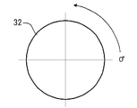
なお、表1における現像ローラ32の汲み上げ極と汲み上げ補助部材35の位置は、図4に示すように、現像ローラ32の中心を通る水平線の現像領域側(感光体ドラム1と対向する側)を0°とし、反時計回りの角度で表したものである。
As shown in FIG. 4, the position of the drawing-up pole of the developing
この表1に示すように、汲み上げ補助部材を有さない比較例1では、画像ムラが許容限度外(×印)で粒状度が許容範囲内(△印)であるのに対し、汲み上げ補助部材35を設けた実施例1では、画像ムラ及び粒状度とも許容範囲内となっている。また、汲み上げ極と汲み上げ補助部材35の角度を同じにした(直線状配置の)実施例2では、画像ムラの程度がより優れた評価を得られた。さらに、汲み上げ極と汲み上げ補助部材35の角度が同じで補助部材35を回転させた実施例3では、画像ムラの程度がさらに向上している(◎印)。そして、キャリア粒径を35μmとした実施例4では、粒状度の効果が向上(○印)し、小粒径キャリアを用いたことで画質向上に効果のあることがわかる。本例の現像装置では、キャリアとしては平均粒径20〜50μmのものを用いることが、画質面から望ましい。
As shown in Table 1, in Comparative Example 1 having no pumping auxiliary member, the image unevenness is outside the allowable limit (x mark) and the granularity is within the allowable range (Δ mark). In Example 1 in which 35 is provided, both the image unevenness and the granularity are within the allowable range. In Example 2 in which the angle of the pumping pole and the pumping
最後に、本発明による現像装置を備える画像形成装置の一例を、図10を参照して説明する。なお、図10の画像形成装置は図1の現像装置3を備えるものであるが、装置レイアウトの変更により図2の現像装置30を装着することも可能である。 Finally, an example of an image forming apparatus including the developing device according to the present invention will be described with reference to FIG. The image forming apparatus of FIG. 10 includes the developing device 3 of FIG. 1, but the developing device 30 of FIG. 2 can be mounted by changing the apparatus layout.
図10に示す画像形成装置はプリンタであり、このプリンタ本体のほぼ中央部には感光体ドラム1を中心とする作像部が配設されている。感光体ドラム1の周囲には、帯電手段2,現像装置3,転写手段4,クリーニング手段5及び除電手段6等が配設されている。作像部の上方には公知の光書込み装置8が設けられている。作像部の下方には、給紙カセット9が配置されている。また、作像部の図において左方には定着装置10が配設されている。転写手段4と定着装置10の間は搬送ベルト7により連絡されている。
The image forming apparatus shown in FIG. 10 is a printer, and an image forming section centered on the
このように構成されたプリンタにおいて、書き込みのための信号は図示しないホストマシーン、例えばコンピュータから送られてくる。受信した画像信号に基づいて露光装置8が駆動され、露光装置のレーザ光源からの光は、モータにより回転駆動されるポリゴンミラーによって走査され、ミラー等を経て、帯電手段2により一様に帯電された感光体ドラム1に照射され、感光体1上に書き込み情報に対応した潜像を形成する。感光体ドラム1上に形成された潜像は、現像装置3で現像され、トナー像となって該感光体ドラム1の表面に形成・保持される。
In the printer configured as described above, a signal for writing is sent from a host machine (not shown) such as a computer. The
一方、給紙カセット9内に収納された用紙束の最上位の用紙が給紙ローラ26により給送され、レジストローラ27により感光体ドラム1のトナー像とのタイミングを取って送出される。
On the other hand, the uppermost sheet of the sheet bundle stored in the sheet feeding cassette 9 is fed by the
感光体ドラム1上のトナー像は、転写手段4により、用紙上に転写される。トナー像転写後の感光体ドラム1の表面に残留するトナーは、クリーニング手段5によってクリーニングされ、その後感光体ドラム1は除電手段6で除電され次の作像サイクルに備える。
The toner image on the
トナー像転写後の用紙は搬送ベルト7により定着装置10に送られ、熱と圧力とによりトナー像が用紙上に定着される。トナー像定着後の用紙は、排紙ローラ28によりトレイ29上に排出されスタックされる。
The paper after transfer of the toner image is sent to the fixing
本例のプリンタでは、少なくとも感光体ドラム1と現像装置3とをプロセスカートリッジとして一体的に構成し、装置本体に対して着脱可能に設けている。なお、クリーニング手段5等、他の機器をプロセスカートリッジに搭載しても良い。
In the printer of this example, at least the
以上、本発明を図示例により説明したが、本発明はこれに限定されるものではない。
例えば、一成分現像剤を用いる現像装置にも本発明の適用が可能である。また、現像装置の構成は適宜変更することができ、例えば攪拌スクリューは2本に限らない。攪拌スクリューが複数本ある場合、汲み上げ補助部材は、図示例で説明したように現像ローラに一番近い攪拌スクリューと現像ローラの間に配置するものとする。また、層厚規制部材もブレードに限らず、層厚規制ローラ等でも良い。
As mentioned above, although this invention was demonstrated by the example of illustration, this invention is not limited to this.
For example, the present invention can be applied to a developing device using a one-component developer. Further, the configuration of the developing device can be changed as appropriate. For example, the number of stirring screws is not limited to two. When there are a plurality of stirring screws, the pumping assisting member is disposed between the stirring screw closest to the developing roller and the developing roller as described in the illustrated example. The layer thickness regulating member is not limited to a blade, and may be a layer thickness regulating roller or the like.
また、本発明の現像装置を備えるプロセスカートリッジにおいては、現像装置以外にプロセスカートリッジに組み込む機器は任意である。例えば、現像装置とクリーニング装置とでプロセスカートリッジを構成しても良い。 Further, in the process cartridge provided with the developing device of the present invention, any device incorporated in the process cartridge other than the developing device is arbitrary. For example, a process cartridge may be configured by the developing device and the cleaning device.
また、本発明の現像装置を備える画像形成装置では、作像部や定着部の構成等、適宜な構成とすることができる。もちろん、画像形成装置としてはプリンタに限らず、複写機やファクシミリ、あるいはそれらの複合機であっても良い。 Further, the image forming apparatus including the developing device of the present invention can have an appropriate configuration such as the configuration of the image forming unit and the fixing unit. Of course, the image forming apparatus is not limited to a printer, and may be a copying machine, a facsimile, or a complex machine thereof.
1 感光体ドラム
3 現像装置
5 クリーニング手段
30 現像装置
31 現像ケーシング
32 現像ローラ
33a,33b 攪拌スクリュー
34 規制ブレード
35 汲み上げ補助部材
DESCRIPTION OF
Claims (6)
前記現像ローラとスクリュー状攪拌部材の間に磁性体からなる汲み上げ補助部材を配置したことを特徴とする現像装置。 In a developing roller having a developing roller having a magnet roller disposed inside a non-magnetic sleeve and a screw-like stirring member,
A developing device, wherein a pumping auxiliary member made of a magnetic material is disposed between the developing roller and the screw-like stirring member.
Priority Applications (1)
| Application Number | Priority Date | Filing Date | Title |
|---|---|---|---|
| JP2004104469A JP2005292301A (en) | 2004-03-31 | 2004-03-31 | Developing device, process cartridge, image forming apparatus |
Applications Claiming Priority (1)
| Application Number | Priority Date | Filing Date | Title |
|---|---|---|---|
| JP2004104469A JP2005292301A (en) | 2004-03-31 | 2004-03-31 | Developing device, process cartridge, image forming apparatus |
Publications (1)
| Publication Number | Publication Date |
|---|---|
| JP2005292301A true JP2005292301A (en) | 2005-10-20 |
Family
ID=35325322
Family Applications (1)
| Application Number | Title | Priority Date | Filing Date |
|---|---|---|---|
| JP2004104469A Pending JP2005292301A (en) | 2004-03-31 | 2004-03-31 | Developing device, process cartridge, image forming apparatus |
Country Status (1)
| Country | Link |
|---|---|
| JP (1) | JP2005292301A (en) |
Cited By (4)
| Publication number | Priority date | Publication date | Assignee | Title |
|---|---|---|---|---|
| JP2007121624A (en) * | 2005-10-27 | 2007-05-17 | Ricoh Co Ltd | Developing device and image forming apparatus |
| US8032062B2 (en) | 2007-04-13 | 2011-10-04 | Sharp Kabushiki Kaisha | Developing unit and image forming apparatus with magnet bearing members |
| JP2012189636A (en) * | 2011-03-08 | 2012-10-04 | Fuji Xerox Co Ltd | Developing device, visible image forming device and image forming device |
| US9280092B2 (en) | 2014-02-19 | 2016-03-08 | Kyocera Document Solutions Inc. | Developing device and image forming apparatus including the same |
Citations (5)
| Publication number | Priority date | Publication date | Assignee | Title |
|---|---|---|---|---|
| JPS5866977A (en) * | 1981-10-16 | 1983-04-21 | Canon Inc | developing device |
| JPH10319722A (en) * | 1997-05-22 | 1998-12-04 | Mita Ind Co Ltd | Electrostatic latent image developing device |
| JP2001117341A (en) * | 1999-10-20 | 2001-04-27 | Kyocera Mita Corp | Developing device for two-component system developer |
| JP2003295590A (en) * | 2002-04-01 | 2003-10-15 | Ricoh Co Ltd | Container, agent substance storage cartridge, developing device and image forming device |
| JP2004020581A (en) * | 2002-06-12 | 2004-01-22 | Ricoh Co Ltd | Developing device, developer carrier, image forming method and apparatus |
-
2004
- 2004-03-31 JP JP2004104469A patent/JP2005292301A/en active Pending
Patent Citations (5)
| Publication number | Priority date | Publication date | Assignee | Title |
|---|---|---|---|---|
| JPS5866977A (en) * | 1981-10-16 | 1983-04-21 | Canon Inc | developing device |
| JPH10319722A (en) * | 1997-05-22 | 1998-12-04 | Mita Ind Co Ltd | Electrostatic latent image developing device |
| JP2001117341A (en) * | 1999-10-20 | 2001-04-27 | Kyocera Mita Corp | Developing device for two-component system developer |
| JP2003295590A (en) * | 2002-04-01 | 2003-10-15 | Ricoh Co Ltd | Container, agent substance storage cartridge, developing device and image forming device |
| JP2004020581A (en) * | 2002-06-12 | 2004-01-22 | Ricoh Co Ltd | Developing device, developer carrier, image forming method and apparatus |
Cited By (4)
| Publication number | Priority date | Publication date | Assignee | Title |
|---|---|---|---|---|
| JP2007121624A (en) * | 2005-10-27 | 2007-05-17 | Ricoh Co Ltd | Developing device and image forming apparatus |
| US8032062B2 (en) | 2007-04-13 | 2011-10-04 | Sharp Kabushiki Kaisha | Developing unit and image forming apparatus with magnet bearing members |
| JP2012189636A (en) * | 2011-03-08 | 2012-10-04 | Fuji Xerox Co Ltd | Developing device, visible image forming device and image forming device |
| US9280092B2 (en) | 2014-02-19 | 2016-03-08 | Kyocera Document Solutions Inc. | Developing device and image forming apparatus including the same |
Similar Documents
| Publication | Publication Date | Title |
|---|---|---|
| JP2006323238A (en) | Developing device and image forming apparatus having the same | |
| JP5325761B2 (en) | Developing device and image forming apparatus including the same | |
| JP5994405B2 (en) | Developing device and image forming apparatus | |
| JP2009244596A (en) | Developing device and image forming apparatus | |
| JP2005292301A (en) | Developing device, process cartridge, image forming apparatus | |
| JP5887319B2 (en) | Developing device and image forming apparatus having the same | |
| JP5597611B2 (en) | Developing device and image forming apparatus having the same | |
| JP2007086312A (en) | Developing device and image forming apparatus | |
| US9229373B1 (en) | Developing device including a developer feeding member having a rotary shaft, a first transport blade for stirring and transporting developer, a blocking portion for blocking the developer, a paddle extending parallel to the rotary shaft, and a second transport blade for transporting the developer in the opposite direction to the first transport blade, and image forming apparatus therewith | |
| JP5309166B2 (en) | Toner dispersion mechanism, developing device including the same, and image forming apparatus | |
| JP4842193B2 (en) | Development device | |
| JP2017191220A (en) | Developing device and image forming apparatus including the same | |
| JP2009288363A (en) | Developer conveying device, developing device with the same, and image forming apparatus | |
| JP2009109966A (en) | Developer transport device, developing device, and image forming apparatus | |
| CN107870544B (en) | Developing device and image forming apparatus including the same | |
| JP4477970B2 (en) | Developing device, image forming apparatus, and process cartridge | |
| JP4505282B2 (en) | Developing device, process cartridge, and image forming apparatus | |
| JP5452421B2 (en) | Developing device and image forming apparatus including the same | |
| JP5879275B2 (en) | Developing device and image forming apparatus having the same | |
| JP6206256B2 (en) | Developing device and image forming apparatus including the same | |
| JP5064163B2 (en) | Developing device, image forming apparatus | |
| JP4820581B2 (en) | Developing device, image forming apparatus, and process cartridge | |
| JP4464769B2 (en) | Developing device, image forming apparatus, and process cartridge | |
| JP4731218B2 (en) | Development device | |
| JP5499058B2 (en) | Developing device and image forming apparatus |
Legal Events
| Date | Code | Title | Description |
|---|---|---|---|
| A621 | Written request for application examination |
Free format text: JAPANESE INTERMEDIATE CODE: A621 Effective date: 20070316 |
|
| A977 | Report on retrieval |
Free format text: JAPANESE INTERMEDIATE CODE: A971007 Effective date: 20091127 |
|
| A131 | Notification of reasons for refusal |
Free format text: JAPANESE INTERMEDIATE CODE: A131 Effective date: 20091201 |
|
| A131 | Notification of reasons for refusal |
Free format text: JAPANESE INTERMEDIATE CODE: A131 Effective date: 20100302 |
|
| A02 | Decision of refusal |
Free format text: JAPANESE INTERMEDIATE CODE: A02 Effective date: 20100629 |