JP2005292152A - Contact device for substance to be nuclide-transformed - Google Patents
Contact device for substance to be nuclide-transformed Download PDFInfo
- Publication number
- JP2005292152A JP2005292152A JP2005142987A JP2005142987A JP2005292152A JP 2005292152 A JP2005292152 A JP 2005292152A JP 2005142987 A JP2005142987 A JP 2005142987A JP 2005142987 A JP2005142987 A JP 2005142987A JP 2005292152 A JP2005292152 A JP 2005292152A
- Authority
- JP
- Japan
- Prior art keywords
- nuclide conversion
- substance
- nuclide
- multilayer structure
- deuterium
- Prior art date
- Legal status (The legal status is an assumption and is not a legal conclusion. Google has not performed a legal analysis and makes no representation as to the accuracy of the status listed.)
- Withdrawn
Links
Images


Classifications
-
- Y—GENERAL TAGGING OF NEW TECHNOLOGICAL DEVELOPMENTS; GENERAL TAGGING OF CROSS-SECTIONAL TECHNOLOGIES SPANNING OVER SEVERAL SECTIONS OF THE IPC; TECHNICAL SUBJECTS COVERED BY FORMER USPC CROSS-REFERENCE ART COLLECTIONS [XRACs] AND DIGESTS
- Y02—TECHNOLOGIES OR APPLICATIONS FOR MITIGATION OR ADAPTATION AGAINST CLIMATE CHANGE
- Y02E—REDUCTION OF GREENHOUSE GAS [GHG] EMISSIONS, RELATED TO ENERGY GENERATION, TRANSMISSION OR DISTRIBUTION
- Y02E30/00—Energy generation of nuclear origin
- Y02E30/10—Nuclear fusion reactors
Abstract
Description
本発明は、例えば長寿命の放射性廃棄物を短寿命核種或いは安定核種に変換する消滅処理や自然界に豊富な元素から希少な元素を生成する技術等に係る核種変換装置及び核種変換方法に用いる核種変換物質接触装置に関する。 The present invention relates to a nuclide used in a nuclide conversion apparatus and a nuclide conversion method, for example, an annihilation process for converting long-lived radioactive waste to a short-lived nuclide or a stable nuclide, and a technique for generating a rare element from abundant elements in nature. The present invention relates to a conversion substance contact device.
従来、例えば重イオン加速器を用いた核融合反応による重元素合成等のように、微量の核種を核種変換する方法に対して、例えば高レベル放射性廃棄物等に含まれる多量の長寿命放射性核種を短時間のうちに効率的かつ効果的に核種変換する方法として、いわゆる消滅処理が知られている。消滅処理は、高レベル放射性廃棄物に含まれるNP、Am、Cm等のマイナーアクチナイドや、Tc−99及びI−129等の長寿命核分裂生成物や、発熱性のSr−90、Cs−137やRh、Pd等の有用な白金族元素を、各元素の特性に応じて分離(群分離)した後に、半減期の長いマイナーアクチナイド及び核分裂生成物に対して中性子等を照射して核反応を発生させて、短寿命又は非放射性の核種に変換する核種変換処理であり、高レベル放射性廃棄物中に含まれる有用元素や長寿命放射性核種を分離及び回収して有用元素の有効利用を図ると共に、長寿命放射性核種を短寿命或いは安定な核種に変換する。 Conventionally, for example, a large amount of long-lived radionuclide contained in high-level radioactive waste is compared with a method for nuclide conversion of a small amount of nuclide such as heavy element synthesis by a nuclear fusion reaction using a heavy ion accelerator. A so-called annihilation process is known as a method for efficiently and effectively converting nuclides within a short time. The annihilation process includes minor actinides such as NP, Am, and Cm contained in high-level radioactive waste, long-lived fission products such as Tc-99 and I-129, exothermic Sr-90, Cs- After separating useful platinum group elements such as 137, Rh, and Pd according to the characteristics of each element (group separation), the minor actinides and fission products having a long half-life are irradiated with neutrons, etc. This is a nuclide conversion process that generates a nuclear reaction and converts it into short-lived or non-radioactive nuclides. Useful elements are effectively separated by separating and recovering useful elements and long-lived radionuclides contained in high-level radioactive waste. In addition, the long-lived radionuclide is converted to a short-lived or stable nuclide.
消滅処理では、高速増殖炉等の原子炉やアクチノイド専焼炉での中性子照射によるアクチノイド等の消滅処理と、加速器での陽子照射によるアクチノイド等の核破砕処理と、加速器でのガンマ線照射による例えばセシウム、ストロンチウム等の消滅処理との3種類の方法が知られている。原子炉等での中性子照射では、中性子反応断面積が大きいマイナーアクチナイドを合理的に処理することができ、特に、高速の中性子を照射することで核分裂が起こりにくい超ウラン元素を直接核分裂させることができる。ただし、原子炉等の中性子照射では消滅しにくい長寿命核分裂生成物、例えば中性子反応断面積が小さいSr−90、Cs−137等については、加速器を利用した消滅処理が適用される。 In the annihilation process, actinides and other annihilation processes by neutron irradiation in nuclear reactors such as fast breeder reactors and actinoid mono-fired furnaces, actinide and other nuclear fragmentation processes by proton irradiation in accelerators, and cesium by gamma irradiation in accelerators, for example, Three types of methods are known, including annihilation of strontium and the like. Neutron irradiation in nuclear reactors, etc. can rationally process minor actinides with large neutron reaction cross sections, and in particular, direct nuclear fission of transuranium elements that are unlikely to undergo fission by irradiating fast neutrons. be able to. However, an annihilation process using an accelerator is applied to long-lived fission products that are difficult to disappear by neutron irradiation such as a nuclear reactor, such as Sr-90 and Cs-137 having small neutron reaction cross sections.
加速器による消滅処理では、原子炉と異なって未臨界で運転できるため、臨界に関わる安全性に優れていること、設計上の自由度が大きい等の利点があり、陽子加速器と電子線加速器が利用される。陽子加速器を用いる消滅処理では、例えば500MeV〜2GeV程度の高エネルギー陽子を照射して標的核を破砕する核破砕反応を利用しており、核破砕反応を直接利用して核種変換を起こすと共に、標的核の破砕に伴って発生する多数の中性子を標的核周りの未臨界ブランケットに投入して核分裂反応を発生させたり、中性子の捕獲反応によって核種変換反応を発生させる。これにより、例えばネプツニウム、アメリシウム等の超ウラン元素及び長寿命核分裂生成物を消滅することができ、しかも、未臨界ブランケットで発生した熱を回収して発電を行い、陽子加速器の運転に必要な電力を自給することができる。 Unlike the nuclear reactor, the annihilation process using an accelerator can be operated subcritically, so it has advantages such as excellent safety related to criticality and a large degree of freedom in design. Proton accelerator and electron beam accelerator are used. Is done. In the annihilation process using a proton accelerator, for example, a nuclear spallation reaction is performed in which high-energy protons of about 500 MeV to 2 GeV are irradiated to disrupt target nuclei. A large number of neutrons generated by nuclear fragmentation are injected into a subcritical blanket around the target nucleus to generate a fission reaction, or a nuclide conversion reaction is generated by a neutron capture reaction. As a result, for example, transuranium elements such as neptunium and americium and long-lived fission products can be extinguished, and the heat generated by the subcritical blanket can be recovered to generate electricity, which is necessary for the operation of the proton accelerator. Can be self-sufficient.
また、電子線加速器を用いる消滅処理では、例えば電子線の制動輻射で発生するガンマ線や、例えば電子蓄積リングと光キャビティーを組み合わせて逆コンプトン散乱により発生させたガンマ線等による光核反応、例えば(γ、N)反応や(γ、核分裂)反応等の巨大共鳴を利用することによって、例えばストロンチウム、セシウム等の長寿命核分裂生成物や超ウラン元素等を消滅処理する。 In addition, in the annihilation process using an electron beam accelerator, for example, a gamma ray generated by bremsstrahlung of an electron beam, a photonuclear reaction caused by, for example, a gamma ray generated by inverse Compton scattering by combining an electron storage ring and an optical cavity, for example ( For example, long-lived fission products such as strontium and cesium, transuranium elements, and the like are annihilated by utilizing giant resonance such as γ, N) reaction or (γ, fission) reaction.
ところで、上記従来技術の一例による消滅処理のように、原子炉や加速器を利用して核種変換を行う場合、大規模かつ高価な装置を用いなければならず、核種変換に要する費用が嵩むという問題がある。しかも、例えば長寿命核分裂生成物であるCs−137を処理する場合において、100万KW程度の原子力発電所から放出されるCs−137を加速器を利用して他の核種に変換する場合に、必要な電力は数100万KWに達してしまい、高強度かつ大電流の加速器が必要になって効率が悪いという問題がある。 By the way, when performing nuclide conversion using a nuclear reactor or accelerator as in the case of the annihilation process according to the above-described prior art, a large and expensive device must be used, and the cost required for nuclide conversion increases. There is. Moreover, for example, when processing Cs-137, which is a long-lived fission product, necessary when converting Cs-137 released from a nuclear power plant of about 1 million KW into other nuclides using an accelerator. A large amount of electric power reaches several million KW, which requires a high-intensity and high-current accelerator, which is inefficient.
また、例えば軽水炉等の原子炉では熱中性子束が1×10¹⁴/cm2/sec程度であるのに対して、中性子反応断面積が小さいCs−137の核種変換に必要な中性子束は1×1017〜1×1018/cm2/sec程度となり、必要な中性子束を得ることができないという問題がある。本発明は上記事情に鑑みてなされたもので、例えば加速器や原子炉等の大規模な装置に比べて、相対的に小規模な装置で核種変換を行うことが可能な核種変換装置及び核種変換方法に用いる核種変換物質接触装置を提供することを目的とする。 For example, in a nuclear reactor such as a light water reactor, the thermal neutron flux is about 1 × 10 14 / cm 2 / sec, whereas the neutron flux necessary for the nuclide conversion of Cs-137 having a small neutron reaction cross section is 1 × There is a problem that the required neutron flux cannot be obtained because it is about 10 17 to 1 × 10 18 / cm 2 / sec. The present invention has been made in view of the above circumstances, for example, a nuclide conversion apparatus and a nuclide conversion capable of performing nuclide conversion with a relatively small apparatus as compared with a large apparatus such as an accelerator or a nuclear reactor. An object of the present invention is to provide a nuclide conversion substance contact device used in the method.
上記課題を解決して係る目的を達成するために、本発明に関連する核種変換装置は、パラジウム又はパラジウム合金、或いは、パラジウム以外の水素吸蔵金属又はパラジウム合金以外の水素吸蔵合金からなる構造体(実施の形態での構造体11、多層構造体32、陰極72、多層構造体89、多層構造体102)と、前記構造体を両側から挟み込むようにして配置され、前記構造体により密封可能な閉空間をなす吸蔵部(実施の形態での吸蔵室31又は吸蔵容器103又は電解セル83)及び放出部(実施の形態での放出室34又は放出容器101又は真空容器85)と、前記構造体の一方の表面側とされる前記吸蔵部側を、相対的に重水素の圧力が高い状態とする高圧化手段(実施の形態での重水素ボンベ35又は重水素ボンベ106又は電源81)と、前記構造体の他方の表面側とされる前記放出部側を、相対的に重水素の圧力が低い状態とする低圧化手段(実施の形態での、ターボ分子ポンプ38,110及びロータリーポンプ39,111又は真空排気ポンプ91)と、前記構造体の一方の表面上に核種変換を施す物質(実施の形態での133Cs、12C、23Na)を接触させる変換物質接触手段(実施の形態での、ステップS04又はステップS22又はステップS44又はステップS04a)とを備えていることを特徴としている。
In order to solve the above problems and achieve the object, a nuclide conversion device related to the present invention is a structure made of palladium or a palladium alloy, or a hydrogen storage metal other than palladium or a hydrogen storage alloy other than a palladium alloy ( The
上記構成の核種変換装置によれば、多層構造をなす構造体の一方の表面上に核種変換を施す物質が接触させられた状態で、構造体の一方の表面側と他方の表面側との間に重水素の圧力差を設けて、構造体の内部で一方の表面側から他方の表面側へと向かう重水素の流束を生成することで、重水素と核種変換を施す物質とに対して、再現性良く核種変換反応を発生させることができる。 According to the nuclide conversion device having the above-described configuration, the nuclide conversion substance is brought into contact with one surface of the structure having a multilayer structure between the one surface side and the other surface side of the structure. By creating a deuterium pressure difference in the structure and generating a deuterium flux from one surface side to the other surface side inside the structure, The nuclide conversion reaction can be generated with good reproducibility.
さらに、本発明に関連する核種変換装置は、前記高圧化手段は前記吸蔵部に重水素ガスを供給する重水素供給手段(実施の形態での重水素ボンベ35,106)を備え、前記低圧化手段は前記放出部を真空状態にする排気手段(実施の形態での、ターボ分子ポンプ38,110及びロータリーポンプ39,111)を備えていることを特徴としている。
Further, in the nuclide conversion apparatus according to the present invention, the high pressure means includes deuterium supply means (
上記構成の核種変換装置によれば、重水素供給手段によって吸蔵部を加圧すると共に、排気手段によって放出部を真空状態に減圧することによって、構造体に重水素の圧力差を形成することができる。 According to the nuclide conversion device having the above-described configuration, a pressure difference of deuterium can be formed in the structure by pressurizing the occlusion unit by the deuterium supply unit and reducing the discharge unit to a vacuum state by the exhaust unit. .
さらに、本発明に関連する核種変換装置は、前記高圧化手段は、前記吸蔵部に重水素を含む電解溶液(実施の形態での電解溶液84)を供給して前記構造体を陰極として前記電解溶液を電気分解する電気分解手段(実施の形態での電源81)とを備え、前記低圧化手段は前記放出部を真空状態にする排気手段(実施の形態での真空排気ポンプ91)を備えていることを特徴としている。
Further, in the nuclide conversion device according to the present invention, the high pressure means supplies the electrolytic solution containing deuterium (
上記構成の核種変換装置によれば、構造体を陰極として、構造体の一方の表面側で電解溶液を電気分解することによって実効的に大きな圧力で構造体に重水素を吸蔵させることができ、さらに、排気手段によって放出部を真空状態に減圧することによって、構造体に重水素の圧力差を形成することができる。 According to the nuclide conversion device having the above-described structure, deuterium can be occluded in the structure with an effective large pressure by electrolyzing the electrolytic solution on one surface side of the structure using the structure as a cathode, Furthermore, the pressure difference of deuterium can be formed in the structure by depressurizing the discharge portion to a vacuum state by the exhaust means.
さらに、本発明に関連する核種変換装置は、前記変換物質接触手段は、前記構造体の一方の表面上に前記核種変換を施す物質を積層する変換物質積層手段(実施の形態でのステップS04又はステップS44又はステップS04a)を備えていることを特徴としている。 Furthermore, in the nuclide conversion apparatus according to the present invention, the conversion substance contact means is a conversion substance stacking means for stacking a substance to be subjected to the nuclide conversion on one surface of the structure (step S04 in the embodiment or Step S44 or step S04a) is provided.
上記構成の核種変換装置によれば、変換物質積層手段、例えば電着、蒸着、スパッタリング等の成膜処理によって構造体の一方の表面上に核種変換を施す物質を積層することができる。 According to the nuclide conversion device having the above-described configuration, a substance that performs nuclide conversion can be stacked on one surface of the structure by a conversion material stacking means, for example, a film forming process such as electrodeposition, vapor deposition, and sputtering.
さらに、本発明に関連する核種変換装置は、前記変換物質接触手段は、前記吸蔵部に前記核種変換を施す物質を供給して前記構造体の一方の表面を前記核種変換を施す物質を含む気体又は液体に曝す変換物質供給手段(実施の形態でのステップS22)を備えていることを特徴としている。 Further, in the nuclide conversion device according to the present invention, the conversion substance contact means supplies the substance that performs the nuclide conversion to the occlusion unit, and includes a gas that includes the substance that performs the nuclide conversion on one surface of the structure. Alternatively, a conversion substance supply means (step S22 in the embodiment) for exposure to a liquid is provided.
上記構成の核種変換装置によれば、例えば重水素を含む気体又は液体に核種変換を施す物質を混入することで、構造体の一方の表面上に核種変換を施す物質を接触させることができる。 According to the nuclide conversion device having the above configuration, for example, a substance that performs nuclide conversion can be brought into contact with one surface of the structure by mixing a substance that performs nuclide conversion into a gas or liquid containing deuterium.
さらに、本発明に関連する核種変換装置は、前記構造体は、前記他方の表面側から前記一方の表面側に向かい、順次、パラジウム又はパラジウム合金或いはパラジウム以外の水素吸蔵金属又はパラジウム合金以外の水素吸蔵合金からなる基材(実施の形態でのPd基板23)と、前記基材の表面上に形成され、パラジウム又はパラジウム合金或いはパラジウム以外の水素吸蔵金属又はパラジウム合金以外の水素吸蔵合金と、これらに対して相対的に仕事関数が低い物質(実施の形態でのCaO)とからなる混合層(実施の形態での混合層22)と、前記混合層の表面上に形成され、パラジウム又はパラジウム合金或いはパラジウム以外の水素吸蔵金属又はパラジウム合金以外の水素吸蔵合金からなる表面層(実施の形態でのPd層21)とを備えて構成されていることを特徴としている。
Further, in the nuclide conversion device according to the present invention, the structure is directed to the one surface side from the other surface side, and sequentially, palladium, palladium alloy, hydrogen storage metal other than palladium, or hydrogen other than palladium alloy. A base material made of a storage alloy (
上記構成の核種変換装置によれば、多層構造をなす構造体に、仕事関数が低い物質を含む混合層を設けることで、核種変換反応の発生の再現性を向上させることができる。 According to the nuclide conversion device having the above-described configuration, the reproducibility of the occurrence of the nuclide conversion reaction can be improved by providing a mixed layer including a substance having a low work function in the structure having a multilayer structure.
また、本発明に関連する核種変換方法は、パラジウム又はパラジウム合金、或いは、パラジウム以外の水素吸蔵金属又はパラジウム合金以外の水素吸蔵合金からなる構造体(実施の形態での構造体11、多層構造体32、陰極72、多層構造体89、多層構造体102)に対して、前記構造体の一方の表面側を相対的に重水素の圧力が高い状態とする高圧化処理(実施の形態でのステップS07又はステップS25又はステップS46)と、前記構造体の他方の表面側を相対的に重水素の圧力が低い状態とする低圧化処理(実施の形態でのステップS05又はステップS23又はステップS45)と、前記構造体の一方の表面上に核種変換を施す物質を接触させる変換物質接触処理(実施の形態での、ステップS04又はステップS22又はステップS44又はステップS04a)とを含むことを特徴としている。
In addition, the nuclide conversion method related to the present invention includes a structure made of palladium or a palladium alloy, or a hydrogen storage metal other than palladium or a hydrogen storage alloy other than a palladium alloy (
上記のような核種変換方法によれば、多層構造をなす構造体の一方の表面上に核種変換を施す物質が接触させられた状態で、構造体の一方の表面側と他方の表面側との間に重水素の圧力差を設けて、構造体の内部で一方の表面側から他方の表面側へと向かう重水素の流束を生成することで、重水素と核種変換を施す物質とに対して、再現性良く核種変換反応を発生させることができる。 According to the nuclide conversion method as described above, in a state where a substance that performs nuclide conversion is brought into contact with one surface of a structure having a multilayer structure, the one surface side and the other surface side of the structure A deuterium pressure difference is provided between the deuterium and the nuclide-converting substance by generating a deuterium flux from one surface side to the other surface side within the structure. Thus, the nuclide conversion reaction can be generated with high reproducibility.
さらに、本発明に関連する核種変換方法では、前記変換物質接触処理は、前記構造体の一方の表面上に前記核種変換を施す物質を積層する変換物質積層処理(実施の形態でのステップS04又はステップS44又はステップS04a)、又は、前記構造体の一方の表面上を前記核種変換を施す物質を含む気体又は液体に曝す変換物質供給処理(実施の形態でのステップS22)の何れかの処理を含むことを特徴としている。 Further, in the nuclide conversion method according to the present invention, the conversion substance contact treatment includes a conversion substance stacking process (step S04 in the embodiment or step S4) in which a substance to be subjected to the nuclide conversion is stacked on one surface of the structure. Step S44 or step S04a), or any one of the conversion substance supply process (step S22 in the embodiment) in which one surface of the structure is exposed to a gas or liquid containing the substance that performs the nuclide conversion. It is characterized by including.
上記のような核種変換方法によれば、変換物質積層処理、例えば電着、蒸着、スパッタリング等の成膜処理によって構造体の一方の表面上に核種変換を施す物質を積層する、又は、例えば重水素を含む気体又は液体に核種変換を施す物質を混入することで、構造体の一方の表面上に核種変換を施す物質を接触させることができる。 According to the nuclide conversion method as described above, a substance to be subjected to nuclide conversion is laminated on one surface of the structure by a conversion substance laminating process, for example, a film forming process such as electrodeposition, vapor deposition, sputtering, or the like. By mixing a substance that performs nuclide conversion into a gas or liquid containing hydrogen, the substance that performs nuclide conversion can be brought into contact with one surface of the structure.
さらに、本発明に関連する核種変換方法では、前記変換物質接触処理は、前記核種変換を施す物質を前記構造体の一方の表面上に接触させることを特徴としている。 Furthermore, in the nuclide conversion method according to the present invention, the conversion substance contact treatment is characterized in that a substance to be subjected to the nuclide conversion is brought into contact with one surface of the structure.
上記のような核種変換方法によれば、核種変換を施す物質を同位体比構成が類似した核種へと変換させることで、核種変換反応の発生を促進することができる。 According to the nuclide conversion method as described above, the occurrence of the nuclide conversion reaction can be promoted by converting the substance subjected to nuclide conversion into a nuclide having a similar isotope ratio configuration.
本発明に関連する核種変換装置によれば、例えば原子炉や加速器等に比べて相対的に小規模な構成で核種変換を行うことができ、構造体の一方の表面側と他方の表面側との間に重水素の圧力差を設けて、構造体の内部で一方の表面側から他方の表面側へと向かう重水素の流束を生成することで、重水素と核種変換を施す物質とに対して、再現性良く核種変換反応を発生させることができる。さらに、本発明に関連する核種変換装置によれば、重水素供給手段によって吸蔵部を加圧すると共に、排気手段によって放出部を真空状態に減圧することによって、構造体に重水素の圧力差を容易に形成することができる。さらに、本発明に関連する核種変換装置によれば、構造体の一方の表面側で電解溶液を電気分解することによって実効的に大きな圧力で構造体に重水素を吸蔵させることができ、さらに、排気手段によって放出部を真空状態に減圧することによって、構造体に重水素の圧力差を容易かつ確実に形成することができる。 According to the nuclide conversion apparatus related to the present invention, for example, nuclide conversion can be performed with a relatively small-scale configuration as compared with a nuclear reactor, an accelerator, etc., and one surface side and the other surface side of the structure By creating a deuterium pressure difference between the two surfaces and generating a deuterium flux from one surface side to the other surface side in the structure, the deuterium and nuclide conversion material On the other hand, the nuclide conversion reaction can be generated with good reproducibility. Further, according to the nuclide conversion apparatus related to the present invention, the pressure difference of the deuterium is easily applied to the structure by pressurizing the occlusion portion by the deuterium supply means and reducing the discharge portion to the vacuum state by the exhaust means. Can be formed. Furthermore, according to the nuclide conversion apparatus related to the present invention, deuterium can be occluded in the structure with an effective large pressure by electrolyzing the electrolytic solution on one surface side of the structure, By depressurizing the discharge portion to a vacuum state by the exhaust means, a pressure difference of deuterium can be easily and reliably formed in the structure.
さらに、本発明に関連する核種変換装置によれば、変換物質積層手段、例えば電着、蒸着、スパッタリング等の成膜処理によって構造体の一方の表面上に核種変換を施す物質を容易に積層することができる。さらに、本発明に関連する核種変換装置によれば、重水素を含む気体又は液体に核種変換を施す物質を混入することで、構造体の一方の表面上に核種変換を施す物質を容易に接触させることができる。さらに、本発明に関連する核種変換装置によれば、多層構造をなす構造体に、仕事関数が低い物質を含む混合層を設けることで、核種変換反応の発生の再現性を向上させることができる。なお、本発明に関連する核種変換装置において、核種変換を施す物質を同位体比構成が類似した核種へと変換させることで、核種変換反応の発生を促進することができ、核種変換反応の発生に対して再現性を向上させることができる。 Furthermore, according to the nuclide conversion apparatus related to the present invention, a substance for performing nuclide conversion is easily laminated on one surface of the structure by a film forming process such as electrodeposition, vapor deposition, sputtering, etc. be able to. Furthermore, according to the nuclide conversion apparatus related to the present invention, a substance that performs nuclide conversion is easily brought into contact with one surface of the structure by mixing a substance that performs nuclide conversion into a gas or liquid containing deuterium. Can be made. Furthermore, according to the nuclide conversion apparatus related to the present invention, the reproducibility of the occurrence of the nuclide conversion reaction can be improved by providing a mixed layer containing a substance having a low work function in the multilayer structure. . In addition, in the nuclide conversion apparatus related to the present invention, the nuclide conversion reaction can be promoted by converting the substance subjected to nuclide conversion into a nuclide having a similar isotope ratio configuration, and the occurrence of the nuclide conversion reaction Reproducibility can be improved.
また、本発明に関連する核種変換方法によれば、構造体の内部で一方の表面側から他方の表面側へと向かう重水素の流束を生成することで、重水素と核種変換を施す物質とに対して、再現性良く核種変換反応を発生させることができる。さらに、本発明に関連する核種変換方法によれば、例えば電着、蒸着、スパッタリング等の成膜処理によって構造体の一方の表面上に核種変換を施す物質を積層する、又は、例えば重水素を含む気体又は液体に核種変換を施す物質を混入することで、構造体の一方の表面上に核種変換を施す物質を容易に接触させることができる。さらに、本発明に関連する核種変換方法によれば、核種変換を施す物質を同位体比構成が類似した核種へと変換させることで、核種変換反応の発生を促進することができ、核種変換反応の発生に対して再現性を向上させることができる。 Further, according to the nuclide conversion method related to the present invention, a substance that performs deuterium and nuclide conversion by generating a deuterium flux from one surface side to the other surface side inside the structure. In contrast, the nuclide conversion reaction can be generated with high reproducibility. Further, according to the nuclide conversion method related to the present invention, for example, a material for performing nuclide conversion is laminated on one surface of the structure by film formation processing such as electrodeposition, vapor deposition, sputtering, or deuterium is used, for example. By mixing a substance that performs nuclide conversion into the gas or liquid that is contained, the substance that performs nuclide conversion can be easily brought into contact with one surface of the structure. Furthermore, according to the nuclide conversion method related to the present invention, the nuclide conversion reaction can be promoted by converting the substance subjected to the nuclide conversion into a nuclide having a similar isotope ratio configuration, and the nuclide conversion reaction can be promoted. It is possible to improve the reproducibility with respect to the occurrence of.
以下、本発明の第1の実施形態に係る核種変換装置及び核種変換方法ついて添付図面を参照しながら説明する。図1は本発明の第1の実施形態に係る核種変換方法の原理を説明する図であり、図2は、本発明の第1の実施形態に係る核種変換方法にて使用される構造体11を示す断面構成図であり、図3は、本発明の第1の実施形態に係る核種変換装置30の構成図であり、図4は、図3に示す核種変換装置30での多層構造体32を示す断面構成図であり、図5(a)は混合層22の断面構成図であり、図5(b)は混合層22を含む構造体11の断面構成図であり、図6は、構造体11に核種変換を施す物質を添加する装置の構成図である。
Hereinafter, a nuclide conversion apparatus and a nuclide conversion method according to a first embodiment of the present invention will be described with reference to the accompanying drawings. FIG. 1 is a diagram for explaining the principle of the nuclide conversion method according to the first embodiment of the present invention, and FIG. 2 is a
本実施の形態による核種変換方法を実現する装置10は、例えば図1に示すように、パラジウム(Pd)またはPdの合金、あるいはその他の水素を吸蔵する金属(例えば、Ti等)またはこれらの合金等からなる、例えば略板状の構造体11と、この構造体11の両面のうち、一方の表面11A上に付着された核種変換を施す物質14とを備え、構造体11の一方の表面11A側が例えば加圧あるいは電気分解等により重水素の圧力が高い領域12とされ、他方の表面11B側が例えば真空排気等により重水素の圧力が低い領域13とされることで構造体11内に重水素の流れ15が生成され、重水素と核種変換を施す物質14とが反応することによって核種変換が行われる装置である。ここで、構造体11は、例えば図2に示すように、好ましくはPd基板23の表面上に、相対的に仕事関数が低い物質つまり電子を放出し易い物質(例えば、仕事関数が3eV未満の物質)とPdとの混合層22が形成され、この混合層22の表面上にPd層21が積層されて形成されている。
An
図3に示すように、本実施の形態による核種変換装置30は、内部が気密保持可能とされた吸蔵室31と、この吸蔵室31の内部にて多層構造体32を介して気密保持可能に設けられた放出室34と、バリアブルリークバルブ33を介して吸蔵室31内に重水素を供給する重水素ボンベ35と、放出室34内の真空度を検出する放出室真空計36と、例えば多層構造体32から生成されるガス状の反応生成物を検出すると共に放出室34内の重水素量を計測することにより多層構造体32を透過する重水素の透過量を評価する質量分析器37と、放出室34内を常に真空状態に保つターボ分子ポンプ38と、放出室34及びターボ分子ポンプ38内を荒引きするためのロータリーポンプ39とを備えて構成されている。
As shown in FIG. 3, the
さらに、核種変換装置30は、例えばX線や電子線、粒子線等の照射により励起された多層構造体32の表面上の原子から放出される光電子やイオン等を検出する静電アナライザー40と、多層構造体32の両面のうち吸蔵室31内の重水素に曝される表面上にX線を照射するXPS(X-ray Photo-electron Spectrometry:X線照射光電子スペクトル分析)用のX線銃41と、内部に重水素が導入された吸蔵室31内の圧力を検出する圧力計42と、例えばベリリウム窓43を有する高純度ゲルマニウム検出器44からなるX線検出器と、吸蔵室31内の真空度を検出する吸蔵室真空計45と、例えば重水素の導入以前等に吸蔵室31内を真空状態に保持する真空バルブ46と、吸蔵室31を真空状態にするターボ分子ポンプ47と、吸蔵室31及びターボ分子ポンプ47内を荒引きするためのロータリーポンプ48とを備えて構成されている。
Furthermore, the
そして、多層構造体32の吸蔵室31側を相対的に重水素の圧力が高い状態とし、多層構造体32の放出室34側を相対的に重水素の圧力が低い状態として、多層構造体32の両面において重水素の圧力差を形成することで、吸蔵室31側から放出室34側へ重水素の流れを作り出す。ここで、例えば図4に示すように、多層構造体32は、Pd基板23の表面上に相対的に仕事関数が低い物質(例えば、仕事関数が3eV未満の物質)とPdとの混合層22が形成され、この混合層22の表面上にPd層21が積層され、さらに、Pd層21の表面上に核種変換を施す物質としてセシウム(Cs)層52が添加されて構成されている。
Then, the
本実施の形態による核種変換装置30は上記構成を備えており、次に、この核種変換装置30を用いて核種変換を行う方法について添付図面を参照しながら説明する。
The
先ず、例えば図2に示すPd基板23(例えば、縦25mm×横25mm×厚さ0.1mm、純度99.5%以上)をアセトン中で所定時間に亘って超音波洗浄することにより脱脂する。そして、真空中(例えば、1.33×10⁻⁵Pa以下)において、例えば900℃の温度で所定時間(例えば、10時間)に亘ってアニールつまり加熱処理を行う(ステップS01)。次に、例えば室温でアニール後のPd基板23を重王水により所定時間(例えば、100秒間)に亘ってエッチング処理を施して表面の不純物を除去する(ステップS02)。
First, for example, a
次に、アルゴンイオンビームによるスパッター法を用いて、エッチング処理後のPd基板23上に成膜処理を施して構造体11を作成する。ここで、例えば図2に示すPd層21の厚さは400・10-10mとし、仕事関数の低い物質とPdとの混合層22は、例えば図5(a)に示すように、例えば厚さ100・10-10mのCaO層57と、例えば厚さ100・10-10mのPd層56とを交互に積層して形成し、この混合層22の厚さを1000・10-10mとした。そして、混合層22の表面上にPd層21を400・10-10mで成膜することにより、構造体11を形成した(ステップS03)。
Next, using a sputtering method using an argon ion beam, a film forming process is performed on the
次に、CsNO3のD2O希薄溶液(CsNO3/D2O溶液)の電気分解により、核種変換を施す物質として、例えばCsを構造体11の成膜処理表面に添加する。例えば、図6に示す電着装置60のように、1mMのCsNO3/D2O溶液を電解液62として、電源61の陽極に白金陽極63を接続し、陰極に構造体11を接続して、例えば1Vの電圧で10秒間に亘って電気分解を行い、構造体11の表面上で下記化学式(1)に示す反応を発生させてCs層52を添加して、多層構造体32を形成する(ステップS04)。
Next, for example, Cs is added to the film-forming surface of the

そして、多層構造体32のCs層52を吸蔵室31側に向けて、多層構造体32を介在させて吸蔵室31と放出室34とをそれぞれ気密状態に閉塞して、先ず、放出室34をロータリーポンプ39およびターボ分子ポンプ38により真空排気する。そして、バリアブルリークバルブ33を閉じ、真空バルブ46を開いて吸蔵室31をロータリーポンプ48およびターボ分子ポンプ47により真空排気する(ステップS05)。次に、吸蔵室31の真空度が充分安定した後(例えば、1×10⁻⁵Pa以下の状態)に、XPSにより吸蔵室31側の多層構造体32の表面上に存在する元素を分析する(ステップS06)。すなわち、X線銃41からのX線を多層構造体32の表面に照射して、このX線の照射により励起された多層構造体32の表面上の原子から放出される光電子のエネルギーを静電アナライザー40により検出する。これにより、多層構造体32の吸蔵室31側の表面上に存在する元素を同定する。
Then, the
次に、多層構造体32を、加熱装置(図示略)により例えば70℃の温度で加熱した後、真空バルブ46を閉じて吸蔵室31の真空排気を停止して、バリアブルリークバルブ33を開いて吸蔵室31内に所定のガス圧力で重水素ガスを導入して、核種変換の実験を開始する。ここで、重水素ガスを導入する際の所定のガス圧力は例えば1.01325×10⁵Pa(いわゆる1気圧)とした。そして、放出室34の質量分析器37でガス状の反応生成物(例えば、質量数A=1〜140)の測定を行い、多層構造体32を透過して放出室34内に放出された重水素の拡散挙動の評価を行う。また、多層構造体32の吸蔵室31側の高純度ゲルマニウム検出器44によりX線の測定を行う(ステップS07)。なお、多層構造体32を透過して放出室34内に放出された重水素量は、例えば放出室真空計36により検出される放出室34内の真空度と、ターボ分子ポンプ38の排気速度とに基づいて算出する。
Next, after heating the
吸蔵室31内に重水素ガスの導入を開始してから所定時間、例えば数十時間後に、多層構造体32の温度を常温に戻す。そして、バリアブルリークバルブ33を閉じて吸蔵室31内への重水素ガスの導入を停止して、さらに、真空バルブ46を開いて吸蔵室31を真空排気して核種変換の実験を終了する。そして、吸蔵室31内の真空度が充分安定した後(例えば、1×10⁻⁵Pa以下の状態)に、XPSにより吸蔵室31側の多層構造体32の表面上に存在する元素を分析して生成物の測定を行う(ステップS08)。
A predetermined time, for example, several tens of hours after the introduction of the deuterium gas into the
そして、上述したステップS06〜ステップS07の処理を繰り返して、核種変換反応の時間変化を測定する(ステップS09)。そして、多層構造体32を核種変換装置30から取り出して、核種変換の実験を終了する(ステップS10)。
And the process of step S06-step S07 mentioned above is repeated, and the time change of nuclide conversion reaction is measured (step S09). Then, the
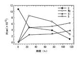
以下に、上述した本実施形態による核種変換方法により行った核種変換実験での2つの実験結果、すなわち同一の実験を2回実施した際の実施例1及び実施例2について図7及び図8を参照しながら説明する。図7は、図4に示す多層構造体32の表面上におけるXPSによるPrのスペクトルを示すグラフ図であり、図8は図4に示す多層構造体32の表面上におけるCs及びPrの原子数の時間変化を表すグラフ図である。実施例1及び実施例2でのXPSの分析結果により、実施例1及び実施例2にて、多層構造体32のCs(原子番号Z=55)は時間が経過するにつれて減少して、例えば図7に示すXPSによるPrのスペクトルのように、Pr(プラセオジウム、原子番号Z=59)が増加した。以下に、XPSによるCs及びPrに対するスペクトルから、各元素の原子数を算出する方法について説明する。
Hereinafter, two experimental results in the nuclide conversion experiment performed by the above-described nuclide conversion method according to the present embodiment, that is, Example 1 and Example 2 when the same experiment was performed twice are shown in FIGS. The description will be given with reference. FIG. 7 is a graph showing the spectrum of Pr by XPS on the surface of the
なお、XPSでの測定時にX線銃41から多層構造体32に対して照射されるX線の強度は常に一定とし、これらのX線が照射されている領域は実施例1及び実施例2の各測定において同一であると仮定した。さらに、多層構造体32の表面上でX線が照射されている領域は、例えば直径5mmの円形領域とし、放出される光電子の脱出深さの見積もりから、XPSにて分析可能な深さは例えば20・10-10mとした。また、Pd基板23を構成するPdはfcc(面心立方格子)結晶なので、XPSにより得られたPdのスペクトルのピーク強度から、Pdの原子数は3.0×10¹⁵個と算出した。
The intensity of X-rays irradiated from the
そして、各元素のイオン化断面積、すなわち元素の内殻電子が例えばX線等を吸収して励起する割合を参照して、XPSにより得られる各元素のスペクトルのピーク強度とPdのスペクトルのピーク強度とを比較することによって、各元素の原子数を算出する。なお、表1には、各元素のイオン化断面積の計算値を、Cの1s軌道に対する値(2.22×10⁻²⁴m2)を「1」とした場合の相対値として示した。なお、下記表1において、Siの2p及びSの2p及びClの2pについては、2p3/2と2p1/2の和として算出した。 Then, referring to the ionization cross section of each element, that is, the ratio of the core electrons of the element that absorb and excite X-rays, for example, the peak intensity of the spectrum of each element and the peak intensity of the Pd spectrum obtained by XPS And the number of atoms of each element is calculated. In Table 1, the calculated values of the ionization cross sections of each element are shown as relative values when the value (2.22 × 10 −24 m 2 ) for C 1s orbital is “1”. In Table 1 below, 2p for Si, 2p for S, and 2p for Cl were calculated as the sum of 2p 3/2 and 2p 1/2 .
図8に示すように、実施例1では、初期状態で1.3×10¹⁴個存在していたCsが、48時間後には8×10¹³個に減少し、120時間後には5×10¹³個に減少している。一方、実験開始以前には存在しなかったPrが48時間後には3×10¹³個検出され、120時間後には7×10¹³個に増加しているのが観測された。同様にして、実施例2においても実験開始からの時間経過に伴って、Csの原子数の減少と、Prの生成及びPrの原子数の増加が観測され、実施例1とほぼ同様の傾向を示している。これにより、CsからPrへの核種変換が起きていると解釈できる。 As shown in FIG. 8, in Example 1, 1.3 × 10 14 Cs present in the initial state decreased to 8 × 10 13 after 48 hours, and 5 × 10 13 after 120 hours. It has decreased to pieces. On the other hand, it was observed that 3 × 10 13 Prs that did not exist before the start of the experiment were detected after 48 hours and increased to 7 × 10 13 after 120 hours. Similarly, in Example 2, the decrease in the number of Cs atoms, the generation of Pr, and the increase in the number of Pr atoms were observed with the passage of time from the start of the experiment, and the same tendency as in Example 1 was observed. Show. Thereby, it can be interpreted that nuclide conversion from Cs to Pr occurs.
なお、以下において、検出されたPrが不純物に由来するものであるか否かについて考察する。上述した本実施形態に係る実施例1及び実施例2では、多層構造体32を吸蔵室31及び放出室34からなる真空容器から取り出すことなく元素分析を行っているので、不純物が混入する原因として考えられるのは重水素ガス(D2ガス)に含まれる不純物と多層構造体32内部の不純物である。D2ガスは例えば純度99.6%であり、不純物としては、N2及びD20が10ppm以下で、O2及びCO2及びCOが5ppm以下とされており、核種変換装置30内でD2ガスを分析した場合にも、これらの不純物及び炭化水素以外のガスは検出されなかった。
In the following, it will be considered whether or not the detected Pr is derived from impurities. In Example 1 and Example 2 which concern on this embodiment mentioned above, since the elemental analysis is performed without taking out the
一方、多層構造体32においては、Pdの純度は99.5%、CaO及びCsNO3の純度は99.9%である。また、グロー放電質量分析法(GD−MS)によって実験開始以前の多層構造体32に対してランタノイド(57La〜71Lu)の定量分析を行った結果、Ndが0.02ppm検出され、Nd以外の他のランタノイドは検出限界以下、つまり0.01ppm以下であった。ここで、実施例1及び実施例2で使用した多層構造体32(例えば、0.7g≒7×10⁻³mol)内に、検出限界である0.01ppmのPrが存在していると仮定すると、多層構造体32中にPrの原子が4.2×10¹³個存在することになる。
On the other hand, in the
この場合、実施例1及び実施例2にて検出されたPr原子は、上記仮定に基づく検出限界以下のPr原子に起因すると仮定すると、これらの検出限界以下の全てのPr原子が多層構造体32の表面上から数10・10-10mの深さの領域に濃縮するようにして配置されていると仮定する必要があり、多層構造体32中に不純物として分散配置されているPr原子が、多層構造体32の表面近傍にのみ集中するような物理現象は熱力学的に不可能であり、実施例1及び実施例2にて検出されたPr原子が、予め多層構造体32中に含まれていた不純物であると結論することはできない。しかも、予め多層構造体32中に含まれていた不純物であれば、原子数の時間変化は観測されずに一定値を保持すると判断できる。以上より、実施例1及び実施例2にて検出されたPrは、核種変換反応の結果として生成されたと結論できる。
In this case, assuming that the Pr atoms detected in Example 1 and Example 2 are caused by Pr atoms below the detection limit based on the above assumption, all the Pr atoms below the detection limit are included in the
なお、上述した実施例1及び実施例2での実験結果は、例えば、米国原子力学会が発行しているFusion Technology誌(Y. Iwamura, T. Itoh, N. Gotoh andI.
Toyoda, "Detection of Anomalous Elements, X-ray and Excess Heat in aD2-Pd
System and its Interpretation by the Electron-Induced Nuclear Reaction
Model", Fusion Technology, vol.33, No.4,P.476,1998)に掲載されたEINRモデルによって非常に良く説明できる。このEINRモデルによれば、PrはCsから下記数式(1)及び(2)によって生成されると考えられる。なお、下記化学式(2)及び(3)において、dは重水素、eは電子、2nはダイニュートロン、νはニュートリノをそれぞれ示している。
In addition, the experimental result in Example 1 and Example 2 mentioned above is, for example, Fusion Technology magazine (Y. Iwamura, T. Itoh, N. Gotoh and I.
Toyoda, "Detection of Anomalous Elements, X-ray and Excess Heat in aD2-Pd
System and its Interpretation by the Electron-Induced Nuclear Reaction
Model ", Fusion Technology, vol.33, No.4, P.476, 1998), which can be explained very well by the EINR model. According to this EINR model, Pr is calculated from Cs as shown in the following formula (1) and In the following chemical formulas (2) and (3), d represents deuterium, e represents an electron, 2 n represents a dyneutron, and ν represents a neutrino.
化学式(2)に示すように、EINRモデルでは重水素が電子を捕獲してダイニュートロンが生成し、同時にCs等の物質と反応して核種変換が起きると考えている。なお、化学式(3)でβ崩壊、すなわち141Cs(=133Cs+42n)から141Prへ向かうβ-崩壊の記号は省略した。 As shown in the chemical formula (2), in the EINR model, deuterium captures electrons to generate dyneutrons, and at the same time, reacts with a substance such as Cs to cause nuclide conversion. Incidentally, beta decay by the chemical formula (3), i.e. 141 Cs (= 133 Cs + 4 2 n) from towards 141 Pr beta - decay of symbols is omitted.
上述したように、本実施の形態による核種変換装置10によれば、例えば原子炉や加速器等の相対的に大規模な装置を必要とせずに、相対的に小規模な構成で核種変換の処理を施すことができる。また、本実施の形態による核種変換方法によれば、実験開始以前には検出されず核種変換の実験開始後に増加傾向に検出されたPrの原子数が、供給されたD2ガスや多層構造体32中に予め含まれていた不純物に起因して検出された可能性を廃して、CsからPrへの核種変換反応が生じていることを再現性良く確実に示すことができる。
As described above, according to the
なお、上述した本実施の形態においては、Pd層21の表面上に核種変換を施す物質としてセシウム(Cs)層52を添加して多層構造体32を構成したが、これに限定されず、核種変換を施す物質としてCsの代わりに、例えば炭素(C)等のその他の物質を添加しても良い。以下に、本実施形態の第1変形例として、Pd層21の表面上に核種変換を施す物質として例えば炭素(C)を添加した場合について図9及び図10を参照しながら説明する。図9は実施例3にて、多層構造体32の表面上におけるC及びMg及びSi及びSの各原子数の時間変化を表すグラフ図であり、図10は実施例4にて、多層構造体32の表面上におけるC及びMg及びSi及びSの各原子数の時間変化を表すグラフ図である。
In the above-described embodiment, the
この第1変形例において、上述した第1の実施形態と大きく異なる点は多層構造体32を形成する方法、特に、上述したステップS04での処理である。すなわち、上述したステップS03の後に、Pd基板23及び混合層22及びPd層21からなる構造体11を大気中に曝すことで、Pd層21の表面上に大気中の炭素(C)を付着させて多層構造体32を形成する(ステップS14)。そして、Cが付着したPd層21を吸蔵室31側に向けて、多層構造体32を介在させて吸蔵室31と放出室34とを閉塞して、吸蔵室31及び放出室34の双方をそれぞれ真空排気する(ステップS15)。そして、上述したステップS06以下の処理を行う。
In this first modification, the point that differs greatly from the first embodiment described above is the method of forming the
以下に、この本実施形態の第1変形例による核種変換方法により行った核種変換実験での2つの実験結果、すなわち同一の実験を2回実施した際の実施例3及び実施例4について添付図面を参照しながら説明する。この場合、実施例3及び実施例4でのXPSの分析結果により、実施例3及び実施例4にて、多層構造体32のCは時間が経過するにつれて減少して、反応生成物であるSi及びSと、中間生成物であるMgとが検出された。そして、上述した本実施の形態と同様にして、XPSによるC及びMg及びSi及びSに対するスペクトルから、各元素の原子数を算出した。
Hereinafter, two experimental results in the nuclide conversion experiment performed by the nuclide conversion method according to the first modification of the present embodiment, that is, Example 3 and Example 4 when the same experiment was performed twice are attached drawings. Will be described with reference to FIG. In this case, according to the XPS analysis results in Example 3 and Example 4, in Example 3 and Example 4, C of the
図9に示すように、実施例3では、炭化水素に由来するCの原子数は、実験開始後の44時間後に減少しているのに対し、実験開始以前には存在しなかったMgが44時間後には検出され、しかも、116時間後にはやや減少している。さらに、実験開始以前には存在しなかったSi及びSは、44時間後、116時間後において単調増加している。 As shown in FIG. 9, in Example 3, the number of C atoms derived from hydrocarbons decreased after 44 hours from the start of the experiment, whereas 44 Mg did not exist before the start of the experiment. It is detected after a time and decreases slightly after 116 hours. Furthermore, Si and S that did not exist before the start of the experiment increased monotonically after 44 hours and after 116 hours.
図10に示すように、実施例4では、炭化水素に由来するCの原子数は、実験開始後の24時間後、76時間後、116時間後において単調減少しているのに対し、実験開始以前には存在しなかったMgが24時間後には生成して、しかも、76時間後、116時間後において単調減少している。さらに、実験開始以前には存在しなかったSi及びSは、24時間後、76時間後、116時間後において単調増加している。 As shown in FIG. 10, in Example 4, the number of C atoms derived from hydrocarbons monotonically decreased after 24 hours, 76 hours, and 116 hours after the start of the experiment, whereas the start of the experiment. Mg which did not exist before is formed after 24 hours and decreases monotonically after 76 hours and 116 hours. Furthermore, Si and S that did not exist before the start of the experiment monotonically increased after 24 hours, 76 hours, and 116 hours.
以上の結果より、本実施形態の第1変形例に係る核種変換方法によって、Cが核種変換して、Mg及びSi及びSが生成されたと結果できる。この場合、上述したEINRモデルによると、Cの核種変換は上記化学式(2)及び下記化学式(4)にて表される。なお、化学式(4)においては、ダイニュートロンクラスター(62n、22n)による反応を示した。 From the above results, it can be concluded that C is nuclide-converted and Mg, Si, and S are generated by the nuclide conversion method according to the first modification of the present embodiment. In this case, according to the EINR model described above, the nuclide conversion of C is represented by the above chemical formula (2) and the following chemical formula (4). In the chemical formula (4), the reaction by the dyneutron cluster (6 2 n, 2 2 n) is shown.
以下に、本実施形態の第2変形例として、Pd層21の表面上に核種変換を施す物質として例えばストロンチウム(Sr)を添加した場合について図11から図17を参照しながら説明する。図11は、本実施形態の第2変形例に係る多層構造体32を示す断面構成図であり、図12は、図11に示す多層構造体32の表面上におけるXPSによるMoのスペクトルを示すグラフ図であり、図13および図14は、図11に示す多層構造体32の表面上におけるSr及びMoの原子数の時間変化を表すグラフ図である。図15は天然に存在するMoの同位体存在比を質量数の変化と共に示すグラフ図であり、図16は第5実施例にて多層構造体32の表面上に観測されたMoの同位体存在比を質量数の変化と共に示すグラフ図であり、図17は核種変換を施す物質として添加された天然に存在するSrの同位体存在比を質量数の変化と共に示すグラフ図である。
Hereinafter, as a second modification of the present embodiment, a case where strontium (Sr), for example, is added as a substance that performs nuclide conversion on the surface of the
この第2変形例では、上述した第1の実施形態の多層構造体32において、核種変換を施す物質からなるCs層52の代わりにSr層53を添加した。すなわち、上述した第1の実施形態と大きく異なる点は多層構造体32を形成する方法、特に、上述したステップS04での処理である。なお、この第2変形例では、Pd基板23として、例えば、縦25mm×横25mm×厚さ0.1mm、純度99.9%以上を用いた。この第2変形例では、上述したステップS03の後に、SrOのD2O希薄溶液(Sr(OD)2/D2O溶液)の電気分解により、核種変換を施す物質として、例えばSrを構造体11の成膜処理表面に添加する。例えば、図6に示す電着装置60において、1mMのSr(OD)2/D2O溶液を電解液62として、電源61の陽極に白金陽極63を接続し、陰極に構造体11を接続して、例えば1Vの電圧で10秒間に亘って電気分解を行い、構造体11の表面上で下記化学式(5)に示す反応を発生させてSr層53を添加して、多層構造体32を形成する(ステップS04a)。
In the second modified example, in the
そして、多層構造体32のSr層53を吸蔵室31側に向けて、上述したステップS05以下の処理を行う。
Then, the
以下に、この本実施形態の第2変形例による核種変換方法により行った核種変換実験での2つの実験結果、すなわち同一の実験を2回実施した際の実施例5及び実施例6について添付図面を参照しながら説明する。実施例5及び実施例6でのXPSの分析結果により、実施例5及び実施例6にて、多層構造体32のSr(原子番号Z=38)は時間が経過するにつれて減少して、例えば図12に示すXPSによるMoのスペクトルのように、Mo(モリブデン、原子番号Z=42)が増加した。
Hereinafter, two experimental results in the nuclide conversion experiment performed by the nuclide conversion method according to the second modification of the present embodiment, that is, Example 5 and Example 6 when the same experiment was performed twice are attached drawings. Will be described with reference to FIG. According to the XPS analysis results in Example 5 and Example 6, in Example 5 and Example 6, the Sr (atomic number Z = 38) of the
ここで、XPSにより得られるSr及びMoに対するスペクトルから、各元素の原子数を算出する際には、上述した第1の実施形態と同様の方法を用いた。すなわち、XPSでの測定時にX線銃41から多層構造体32に対して照射されるX線の強度は常に一定とし、これらのX線が照射されている領域は実施例5及び実施例6の各測定において同一であると仮定した。さらに、多層構造体32の表面上でX線が照射されている領域は、例えば直径5mmの円形領域とし、放出される光電子の脱出深さの見積もりから、XPSにて分析可能な深さは例えば20・10-10mとした。また、Pd基板23を構成するPdはfcc(面心立方格子)結晶なので、XPSにより得られたPdのスペクトルのピーク強度から、Pdの原子数は3.0×10¹⁵個と算出した。
Here, when calculating the number of atoms of each element from the spectrum for Sr and Mo obtained by XPS, the same method as in the first embodiment described above was used. That is, the intensity of X-rays irradiated from the
そして、各元素のイオン化断面積、すなわち元素の内殻電子が例えばX線等を吸収して励起する割合を参照して、XPSにより得られる各元素のスペクトルのピーク強度とPdのスペクトルのピーク強度とを比較することによって、各元素の原子数を算出した。 Then, referring to the ionization cross section of each element, that is, the ratio of the core electrons of the element that absorb and excite X-rays, for example, the peak intensity of the spectrum of each element and the peak intensity of the Pd spectrum obtained by XPS And the number of atoms of each element was calculated.
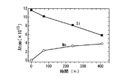
図13に示すように、実施例5では、初期状態で1.2×10¹⁴個存在していたSrが、80時間後には1.0×10¹⁴個に減少し、240時間後には8×10¹³個に減少し、400時間後には4×10¹³個に減少している。一方、実験開始以前には存在しなかったMoが80時間後には約2.2×10¹³個検出され、240時間後には約3.2×10¹³個に増加し、400時間後には3.8×10¹³個に増加しているのが観測された。同様にして、図14に示す実施例6においても、実験開始からの時間経過に伴って、Srの原子数の減少と、実験開始以前には存在しなかったMoの生成及びMoの原子数の増加が観測され、実施例5とほぼ同様の傾向を示している。また、実施例5および実施例6の両方において、Srの原子数の減少の時間変化と、Moの原子数の生成および増加の時間変化とが、ほぼ一致していることから、SrからMoへの核種変換が起きていると解釈できる。しかも、実施例5および実施例6の両方において、定性的に再現性の良い実験結果が得られていると結論することができる。 As shown in FIG. 13, in Example 5, 1.2 × 10 14 Sr present in the initial state decreased to 1.0 × 10 14 after 80 hours, and 8 × after 240 hours. It decreases to 10 13 , and after 400 hours, it decreases to 4 × 10 13 . On the other hand, about 2.2 × 10 13 Mo were detected after 80 hours after the start of the experiment, increased to about 3.2 × 10 13 after 240 hours, and increased to about 3.2 × 10 13 after 400 hours. An increase to 8 × 10 13 was observed. Similarly, in Example 6 shown in FIG. 14, with the passage of time from the start of the experiment, the number of Sr atoms decreased, the generation of Mo that did not exist before the start of the experiment, and the number of Mo atoms. An increase was observed, indicating a tendency similar to that in Example 5. In both Example 5 and Example 6, the time change of the decrease in the number of Sr atoms and the time change of the generation and increase of the number of Mo atoms are almost the same. It can be interpreted that the nuclide conversion has occurred. Moreover, in both Example 5 and Example 6, it can be concluded that experimental results with qualitatively good reproducibility are obtained.
さらに、実施例5においては、核種変換の実験終了後、つまり上述したステップS10の後に、多層構造体32の表面を二次イオン質量分析(SIMS:Secondary Ion Mass Spectroscopy)により分析して、生成されたMoの同位体存在比を算出した。例えば図15に示す天然に存在するMoの同位体存在比に比べて、例えば図16に示す第5実施例にて観測されたMoの同位体存在比では、特定の同位体、すなわち96Moのみが突出して高い存在率を示していることが分かる。ここで、例えば図17に示すように、核種変換を施す物質として多層構造体32に添加された天然に存在するSrの同位体存在比では、特定の同位体、すなわち88Srのみが突出して高い存在率を示していることが分かる。すなわち、核種変換を施す物質(Sr)の同位体存在比と、実験開始以前には存在せずに、実験終了後に生成された物質(Mo)の同位体存在比とが、強い相関関係にあると結論することができ、実施例5および実施例6にて検出されたMoは、Srに対する核種変換により生成されたと結論できる。
Furthermore, in Example 5, after completion of the nuclide conversion experiment, that is, after the above-described step S10, the surface of the
さらに、実施例5及び実施例6での実験結果は、例えば、上述したEINRモデルによって非常に良く説明することができ、例えば96Moは上記化学式(2)及び下記化学式(6)によって生成されると考えられる。なお、化学式(6)でβ崩壊、すなわち96Sr(=88Sr+42n)から96Moへ向かうβ-崩壊の記号は省略した。 Furthermore, the experimental results in Example 5 and Example 6 can be explained very well by, for example, the above-described EINR model. For example, 96 Mo is generated by the above chemical formula (2) and the following chemical formula (6). it is conceivable that. Incidentally, beta decay by the chemical formula (6), i.e. 96 Sr (= 88 Sr + 4 2 n) from toward the 96 Mo beta - decay of symbols is omitted.
以下、本発明の第2の実施形態に係る核種変換装置及び核種変換方法ついて添付図面を参照しながら説明する。図18は本発明の第2の実施形態に係る核種変換方法の原理を説明する図であり、図19は本発明の第2の実施形態に係る核種変換装置80の構成図である。
Hereinafter, a nuclide conversion apparatus and a nuclide conversion method according to a second embodiment of the present invention will be described with reference to the accompanying drawings. FIG. 18 is a diagram for explaining the principle of the nuclide conversion method according to the second embodiment of the present invention, and FIG. 19 is a configuration diagram of the
本実施の形態による核種変換方法を実現する装置70は、例えば図18に示すように、例えば白金等の陽極71と、パラジウム(Pd)またはPdの合金、あるいはその他の水素を吸蔵する金属(例えば、Ti等)またはこの合金等からなる陰極72と、陽極71と陰極72の一方の表面とを浸す重水溶液73と、陰極72により液密とされ、例えば核種変換を施す物質が含まれた重水溶液73が満たされた電解セル74と、陰極72により気密とされた真空容器75とを備え、陰極72の一方の表面72A側が例えば電気分解等により重水素の圧力が高い領域とされ、他方の表面72B側が例えば真空排気等により重水素の圧力が低い領域とされることで陰極72内部に重水素の流れが生成され、重水素と核種変換を施す物質とが反応することによって核種変換が行われる装置である。ここで、陰極72は、例えば図2に示す構造体11と同様の構成を有しており、好ましくはPd基板23の表面上に、相対的に仕事関数が低い物質つまり電子を放出し易い物質(例えば、仕事関数が3eV未満の物質)とPdとの混合層22が形成され、この混合層22の表面上にPd層21が積層されて形成されている。
For example, as shown in FIG. 18, an
図19に示すように、本実施の形態による核種変換装置80は、電源81と、圧力計82を備えた電解セル83と、電解セル83内に貯溜される電解溶液84と、真空容器85と、電解セル83内の電解溶液84を冷却する螺旋状の例えば絶縁性の樹脂等からなる冷却管86と、触媒87と、電源81の陰極に接続されて電解溶液84に浸漬された白金等の陽極電極88と、電解セル83内を液密に保持すると共に、真空容器85内を気密に保持して、電源81の陰極に接続された多層構造体89と、電解セル83及び真空容器85を格納して温度を制御する恒温槽90と、真空容器85内を真空状態とする真空排気ポンプ91とを備えて構成されている。
As shown in FIG. 19, the
ここで、例えば絶縁性の樹脂等からなる電解セル83及び例えばステンレス等からなる真空容器85のそれぞれは、耐薬品性に優れた例えばカルレッツOリング等を介して多層構造体89によって、液密及び気密状態に封止されており、いわば多層構造体89を介して接続されている。また、電解セル83内に貯溜された電解溶液84は、核種変換を施す物質として例えばセシウム(Cs)が含まれた重水溶液、例えば濃度が3.1mol/lのCs2(SO4)重水溶液とされている。なお、触媒87は、白金上に白金黒を電着したものより構成され、電解溶液84の電気分解により発生した大部分の水素及び酸素から水を生成して、再び、電解溶液84に戻す。
Here, each of the
本実施の形態による核種変換装置80は上記構成を備えており、次に、この核種変換装置80を用いて核種変換を行う方法について添付図面を参照しながら説明する。
The
先ず、上述した第1の実施形態に係る核種変換方法におけるステップS01〜ステップS03と同様にして構造体11を作成する。そして、この構造体11を多層構造体89として、この多層構造体89のPd層21を電解セル83側に向けて、電解セル83及び真空容器85をそれぞれ液密及び気密状態に封止する(ステップS21)。次に、電解セル83内に電解溶液84として、例えば濃度が3.1mol/lのCs2(SO4)重水溶液を注入する。さらに、電解セル83内部で電解溶液84が満たされていない空間を窒素ガスで置換して封入し、電解セル83内の圧力を例えば1.5kg/cm2に保持する(ステップS22)。
First, the
そして、真空容器85内を真空ポンプ91にて排気して真空状態に保持する(ステップS23)。そして、例えば絶縁性の樹脂等からなる冷却管86内に冷媒を供給して、電解セル83内の温度を所定の一定温度に保持する(ステップS24)。そして、電解セル83内で電解溶液84に浸漬された例えば白金からなる陽極電極88と、陰極とされる多層構造体89とを電源81に接続して、電源81から供給される電力により電気分解反応を発生させる(ステップS25)。ここで、電気分解時に供給する電流は、例えば3時間で徐々に1Aから2Aへ上昇させ、この後、2Aを保持する。
Then, the inside of the
そして、電気分解開始後、12時間後に恒温槽90の温度を70℃として、以後、この温度を保持する(ステップS26)。この電気分解を所定時間、例えば7日間持続した後に電気分解を停止して、恒温槽90の温度を常温にする(ステップS27)。そして、核種変換装置80から多層構造体89を取り外して、多層構造体89の表面を二次イオン質量分析(SIMS:Secondary Ion Mass Spectroscopy)により分析する(ステップS28)。
Then, 12 hours after the start of electrolysis, the temperature of the
以下に、上述した本実施形態による核種変換方法により行った核種変換実験での実験結果、すなわち実施例7について図20及び図21を参照しながら説明する。図20は、図19に示す核種変換装置80を用いた実験後の多層構造体89の電解セル83側の表面を示す図であり、図21は、図19に示す核種変換装置80を用いた実験後の多層構造体89の表面のSIMS分析結果を示すグラフ図である。
Hereinafter, experimental results in the nuclide conversion experiment performed by the nuclide conversion method according to the present embodiment described above, that is, Example 7 will be described with reference to FIGS. 20 is a diagram showing the surface of the
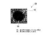
図20に示す重水素が透過した部分96と、図20に示す重水素が透過していない部分95とに対して、図21に示すように、140Ceについては二次イオンの強度が一致しているが、139La及び141Prでは重水素が透過した部分96、すなわち核種変換反応が発生している部分の方が、二次イオンの強度が大きくなっている。また、質量数A=142については、142Ceと142Ndとの何れかであるかを判別することはできないが、重水素が透過した部分96の方が、二次イオンの強度が大きくなっている。これにより、少なくとも141Prは、Csが核種変換されて生成された物質であると結論できる。
The
上述したように、本実施の形態による核種変換装置80によれば、例えば原子炉や加速器等の相対的に大規模な装置を必要とせずに、相対的に小規模な構成で核種変換の処理を施すことができる。しかも、上述した第1の実施の形態に係る核種変換装置30とは異なる構成でありながら、CsからPrへの核種変換反応が生じていることを示す実験結果を得ることができ、本発明の本質的手段の有効性を示すことができる。また、本実施の形態による核種変換方法によれば、多層構造体89における重水素が透過した部分96と、重水素が透過していない部分95との比較から、少なくともCsからPrへの核種変換反応が生じていることを確実に示すことができる。
As described above, according to the
なお、本実施の形態においては、電解溶液84として核種変換を施す物質を含む重水溶液を用いるとしたが、これに限定されず、多層構造体89の一方の表面上に、例えば真空蒸着やスパッター法の成膜処理によって核種変換を施す物質、例えばCsを積層して、このCsが積層された面を電解セル83の内部に向けて、電解セル83に貯溜された重水溶液からなる電解溶液84に浸しても良い。この場合、重水溶液には核種変換を施す物質、つまりCsを含有させる必要はない。
In the present embodiment, a heavy aqueous solution containing a substance that performs nuclide conversion is used as the
なお、上述した本実施の形態においては、電解溶液84としてCsを含む重水溶液を用いるとしたが、これに限定されず、核種変換を施す物質としてCsの代わりに、例えばナトリウム(Na)等のその他の物質を添加しても良い。以下に、本実施形態の変形例として、核種変換を施す物質として例えばナトリウム(Na)を重水溶液に添加した場合について説明する。
In the above-described embodiment, a heavy aqueous solution containing Cs is used as the
この変形例において、上述した第2の実施形態と大きく異なる点は、上述したステップS22以下の処理である。すなわち、上述したステップS21の後に、電解セル83内に電解溶液84として、例えばナトリウムが400ppmだけ添加された、濃度が4.3mol/lのLiOD重水溶液を注入する。さらに、電解セル83内部で電解溶液84が満たされていない空間を窒素ガスで置換して封入し、電解セル83内の圧力を例えば1.5kg/cm2に保持する(ステップS32)。
In this modified example, the point that differs greatly from the second embodiment described above is the processing in step S22 and subsequent steps described above. That is, after the above-described step S21, a LiOD heavy aqueous solution having a concentration of 4.3 mol / l to which, for example, 400 ppm of sodium is added is injected into the
そして、真空容器85内を真空ポンプ91にて排気して真空状態に保持する(ステップS33)。そして、例えば絶縁性の樹脂等からなる冷却管86内に冷媒を供給して、電解セル83内の温度を所定の一定温度に保持する(ステップS34)。そして、電解セル83内で電解溶液84に浸漬された例えば白金からなる陽極電極88と、陰極とされる多層構造体89とを電源81に接続して、電源81から供給される電力により電気分解反応を発生させる(ステップS35)。ここで、電気分解時に供給する電流は、例えば6時間で徐々に0.5Aから2Aへ上昇させ、この後、2Aを保持する。
Then, the inside of the
そして、この電気分解を所定時間、例えば7日間持続した後に電気分解を停止して、恒温槽90の温度を常温にする(ステップS36)。そして、核種変換装置80から多層構造体89を取り外して、多層構造体89の表面を電子プローブ・マイクロ・アナライザー(EPMA:Electron Probe Microanalysis)により分析する(ステップS37)。
Then, after the electrolysis is continued for a predetermined time, for example, 7 days, the electrolysis is stopped and the temperature of the
以下に、上述した本発明の第2の実施形態の変形例に係る核種変換方法により行った3つの核種変換実験での実験結果、すなわち同一の実験を3回実施した際の実施例8及び実施例9及び実施例10について説明する。なお、下記表2には、実施例8及び実施例9及び実施例10に対して、誘導励起プラズマ−オージェ電子スペクトル分析(ICP−AES:Inductive Coupled Plasma - Auger Electron Spectrometry)による電解溶液84の分析結果について示した。なお、実験開始以前における電解溶液84の分析結果を比較例とした。
Hereinafter, experimental results in three nuclide conversion experiments performed by the nuclide conversion method according to the modification of the second embodiment of the present invention described above, that is, Example 8 and implementation when the same experiment was performed three times. Example 9 and Example 10 will be described. In Table 2, the analysis of the
表2に示すように、実験開始以前の電解溶液84にはNaが430ppm、Alは検出限界以下の1ppm以下である。一方、核種変換の実験後には、Naの方が一桁程度低い値の数十ppmとなり、Alが数百ppmとなった。実験の開始前後での電解溶液84の変化は、電源81から電流を与えて電気分解を行うだけであり、外部から他の物質が添加されることはない。また、原子数(表2での、Atom)では、減少したNaの原子数は2.2×10²¹から2.0×10²¹程度であり、Alの増加量にほぼ一致していることが確認できる。
As shown in Table 2, Na is 430 ppm and Al is 1 ppm or less below the detection limit in the
この結果は、上述したEINRモデルでは上記化学式(2)及び下記化学式(7)で表される。 This result is represented by the above chemical formula (2) and the following chemical formula (7) in the above-mentioned EINR model.
ここで、Naは23Naの天然存在率が100%であり、Alは27Alの天然存在率が100%である。従来の実験データから帰納的に同位体比構成の類似した核種同士の間で核種変換が生じやすいと判断でき、NaがAlに変換する可能性が高いことは、Na、Alの両元素とも安定に存在する同位体が唯一であることからも類推できる。また、多層構造体89の表面をEPMAによって分析した結果、多層構造体89の中心部、すなわち重水素が透過した部分からもAlが検出された。Alは両性金属であるため、電解溶液84中に溶解可能であるが、多層構造体89の中心部表面からもAlが検出されていることで、Naが核種変換されてAlが生成されたと結論することができる。
Here, Na has a natural abundance of 23 Na of 100%, and Al has a natural abundance of 27 Al of 100%. From the conventional experimental data, it can be determined that nuclide conversion is likely to occur between nuclides with similar isotope composition, and that Na is likely to be converted to Al. Both Na and Al elements are stable. It can be inferred from the fact that there is only one isotope. Further, as a result of analyzing the surface of the
なお、本実施の形態においては、電解溶液84として核種変換を施す物質を含む重水溶液を用いるとしたが、これに限定されず、多層構造体89の一方の表面上に、例えば真空蒸着やスパッター法の成膜処理によって核種変換を施す物質、例えばNaを積層して、このNaが積層された面を電解セル83の内部に向けて、電解セル83に貯溜された重水溶液からなる電解溶液84に浸しても良い。この場合、重水溶液には核種変換を施す物質、つまりNaを含有させる必要はない。
In the present embodiment, a heavy aqueous solution containing a substance that performs nuclide conversion is used as the
以下、本発明の第3の実施形態に係る核種変換装置及び核種変換方法ついて添付図面を参照しながら説明する。図22は本発明の第3の実施形態に係る核種変換装置100の構成図である。
Hereinafter, a nuclide conversion apparatus and a nuclide conversion method according to a third embodiment of the present invention will be described with reference to the accompanying drawings. FIG. 22 is a configuration diagram of a
本実施の形態による核種変換装置100は、内部が気密保持可能とされた放出容器101と、この放出容器101の内部にて多層構造体102を介して気密保持可能に設けられた吸蔵容器103と、レギュレータバルブ104およびバルブ105を介して吸蔵容器103内に重水素を供給する重水素ボンベ106と、吸蔵容器103内の圧力を検出する圧力計107と、真空バルブ108を介して放出容器101内と吸蔵容器103内とを接続する接続配管109と、放出容器101内を真空状態に保つターボ分子ポンプ110と、放出容器101内及び吸蔵容器103内及びターボ分子ポンプ110内を荒引きするためのロータリーポンプ111と、放出容器101内の真空度を検出する真空計112とを備えて構成されている。
The
本実施の形態による核種変換装置100は上記構成を備えており、次に、この核種変換装置100を用いて核種変換を行う方法について添付図面を参照しながら説明する。
The
先ず、例えば図2に示すPd基板23(例えば、直径70mm×厚さ0.1mm、純度99.9%以上)をアセトン中で所定時間に亘って超音波洗浄することにより脱脂する。そして、Arガス雰囲気中において、例えば900℃の温度で所定時間(例えば、10時間)に亘ってアニールつまり加熱処理を行う(ステップS41)。次に、アニール後のPd基板23に対して、例えば室温にて1.5倍希釈の王水により所定時間(例えば、100秒間)に亘ってエッチング処理を施して表面の不純物を除去する(ステップS42)。
First, for example, the
次に、上述したステップS03と同様にして、アルゴンイオンビームによるスパッター法を用いて、エッチング処理後のPd基板23上に成膜処理を施して構造体11を作成する(ステップS43)。そして、上述したステップS04と同様にして、CsNO3のD2O希薄溶液(CsNO3/D2O溶液)の電気分解により、核種変換を施す物質としてCs層を構造体11の成膜処理表面に添加して、多層構造体102を形成する(ステップS44)。
Next, in the same manner as in step S03 described above, the
そして、多層構造体102のCs層を吸蔵容器103側に向けて、多層構造体102を介在させて吸蔵容器103と放出容器101とをそれぞれ気密状態に閉塞する。そして、先ず、バルブ105を閉じ、接続配管109の真空バルブ108を開いて、放出容器101および吸蔵容器103をロータリーポンプ111およびターボ分子ポンプ110により真空排気する(ステップS45)。
Then, the Cs layer of the
次に、多層構造体102を、加熱装置(図示略)により例えば70℃の温度に加熱した後、真空バルブ108を閉じて吸蔵容器103の真空排気を停止して、バルブ105を開いて吸蔵容器103内に所定のガス圧力で重水素ガスを導入して、核種変換の実験を開始する。ここで、重水素ガスを導入する際の所定のガス圧力はレギュレータバルブ104によって調整し、例えば1.01325×10⁵Pa(いわゆる1気圧)とした(ステップS46)。なお、多層構造体102を透過して放出容器101内に出てきた重水素量は、例えば真空計112により検出される放出容器101内の真空度と、ターボ分子ポンプ110の排気速度とに基づいて算出する。
Next, after the
吸蔵容器103内に重水素ガスの導入を開始してから所定時間、例えば数十時間後に、多層構造体102の温度を常温に戻す。そして、バルブ105を閉じて吸蔵容器103内への重水素ガスの導入を停止して、さらに、真空バルブ108を開いて吸蔵容器103を真空排気して核種変換の実験を終了する(ステップS47)。そして、核種変換装置100から多層構造体102を取り外して、この多層構造体102に王水でエッチング処理を施して、多層構造体102の表面上に存在する元素を溶かした溶液を作成する。この溶液に対して、高周波誘導結合プラズマ−質量分析(ICP−MS:Inductive Coupled Plasma - Mass Spectrometry)を適用して、多層構造体102の表面上に存在する元素の定量分析を行う(ステップS48)。
A predetermined time, for example, several tens of hours after the introduction of deuterium gas into the
以下に、上述した本実施形態による核種変換方法により行った核種変換実験での2つの実験結果、すなわち同一の実験を2回実施した際の実施例11及び実施例12について表3を参照しながら説明する。なお、下記表3には、実施例11及び実施例12に対して、ICP−MSによる分析結果について示した。なお、実験開始以前における多層構造体102に王水でエッチング処理を施して生成した溶液の分析結果を比較例とした。
Hereinafter, two experimental results in the nuclide conversion experiment performed by the above-described nuclide conversion method according to the present embodiment, that is, Example 11 and Example 12 when the same experiment was performed twice with reference to Table 3 will be described. explain. Table 3 below shows the results of analysis by ICP-MS for Example 11 and Example 12. In addition, the analysis result of the solution produced | generated by performing the etching process with aqua regia on the
表3に示すように、比較例での実験開始以前の多層構造体102から得た溶液では、Prの重量が0.008μg、Csの重量は3.8μgである。このPrの量は計測器の検出限界値であり、バックグラウンドノイズとしての値である。これに対して、実施例12ではPrの重量が、バックグラウンドに対し十分高い値の0.12μgであった。さらに、実施例11にて、Prの重量は実施例12と比べて1桁程度高い値の1.3μgに増大し、Csの重量が2.3μgに減少した。すなわち、実施例11及び実施例12にて検出されたPrの増大は、CsからPrへの核種変換反応が発生した結果であると結論できる。しかも、反応断面積を大きくすることで、反応量を増大することができた。
As shown in Table 3, in the solution obtained from the
上述したように、本実施の形態による核種変換装置100によれば、例えば原子炉や加速器等の相対的に大規模な装置を必要とせずに、相対的に小規模な構成で核種変換の処理を施すことができる。しかも、上述した第1の実施の形態に係る核種変換装置30とは異なる装置構成および異なる形状の多層構造体102でありながら、CsからPrへの核種変換反応が生じていることを示す実験結果を得ることができ、本発明の本質的手段の有効性を示すことができる。
As described above, according to the
また、上述した本発明の第1の実施形態及び第2の実施形態及び第3の実施形態においては、水素を吸蔵する金属としてパラジウム(Pd)を使用したが、これに限定されず、Pdの合金、或いは、例えばTi、Ni、V、Cu等のその他の水素を吸蔵する金属、又はこれらの合金等であってもよい。 In the first embodiment, the second embodiment, and the third embodiment of the present invention described above, palladium (Pd) is used as a metal that absorbs hydrogen. However, the present invention is not limited to this. It may be an alloy, or another metal that occludes hydrogen such as Ti, Ni, V, or Cu, or an alloy thereof.
10,30,70,80,100 核種変換装置
11 構造体
21 Pd層(表面層)
22 混合層
23 Pd基板(基材)
31 吸蔵室(吸蔵部)
32,89,102 多層構造体(構造体)
34 放出室(放出部)
35,106 重水素ボンベ(高圧化手段、重水素供給手段)
38,110 ターボ分子ポンプ(低圧化手段、排気手段)
39,111 ロータリーポンプ(低圧化手段、排気手段)
72 陰極(構造体)
81 電源(高圧化手段、電気分解手段)
83 電解セル(吸蔵部)
84 電解溶液
85 真空容器(放出部)
91 真空排気ポンプ(低圧化手段、排気手段)
101 放出容器(放出部)
102 吸蔵容器(吸蔵部)
10, 30, 70, 80, 100
22
31 Occupation room (Occupation part)
32,89,102 Multilayer structure (structure)
34 Release chamber (discharge section)
35,106 Deuterium cylinder (high pressure means, deuterium supply means)
38,110 Turbo molecular pump (low pressure means, exhaust means)
39,111 Rotary pump (low pressure means, exhaust means)
72 Cathode (structure)
81 Power supply (high pressure means, electrolysis means)
83 Electrolysis cell (occlusion)
84
91 Vacuum pump (low pressure means, exhaust means)
101 Discharge container (discharge part)
102 Occlusion container (occlusion part)
Claims (6)
前記構造体の前記一方の表面に核種変換を施す物質を接触させることを特徴とする核種変換物質接触装置。 Contacted on one surface of a structure having palladium or a palladium alloy, or a hydrogen storage metal other than palladium or a hydrogen storage alloy other than palladium alloy, and a material having a relatively low work function. For a substance that performs nuclide conversion, it is provided in a nuclide conversion apparatus in which deuterium flows from the one surface side of the structure toward the other surface side,
A nuclide conversion substance contact device, wherein a substance that performs nuclide conversion is brought into contact with the one surface of the structure.
Priority Applications (1)
| Application Number | Priority Date | Filing Date | Title |
|---|---|---|---|
| JP2005142987A JP2005292152A (en) | 2000-10-31 | 2005-05-16 | Contact device for substance to be nuclide-transformed |
Applications Claiming Priority (2)
| Application Number | Priority Date | Filing Date | Title |
|---|---|---|---|
| JP2000333640 | 2000-10-31 | ||
| JP2005142987A JP2005292152A (en) | 2000-10-31 | 2005-05-16 | Contact device for substance to be nuclide-transformed |
Related Parent Applications (1)
| Application Number | Title | Priority Date | Filing Date |
|---|---|---|---|
| JP2001201875A Division JP4346838B2 (en) | 2000-10-31 | 2001-07-03 | Nuclide converter |
Publications (1)
| Publication Number | Publication Date |
|---|---|
| JP2005292152A true JP2005292152A (en) | 2005-10-20 |
Family
ID=35325201
Family Applications (1)
| Application Number | Title | Priority Date | Filing Date |
|---|---|---|---|
| JP2005142987A Withdrawn JP2005292152A (en) | 2000-10-31 | 2005-05-16 | Contact device for substance to be nuclide-transformed |
Country Status (1)
| Country | Link |
|---|---|
| JP (1) | JP2005292152A (en) |
-
2005
- 2005-05-16 JP JP2005142987A patent/JP2005292152A/en not_active Withdrawn
Similar Documents
| Publication | Publication Date | Title |
|---|---|---|
| JP4346838B2 (en) | Nuclide converter | |
| JP5522566B2 (en) | Radioisotope production method and apparatus | |
| Lindner et al. | Nonfission inelastic events in uranium and thorium induced by high-energy protons | |
| Storms | An explanation of low-energy nuclear reactions (cold fusion) | |
| JP4347262B2 (en) | Nuclide conversion device and nuclide conversion method | |
| Diamond et al. | Actinium-225 production with an electron accelerator | |
| JP2005292154A (en) | Nuclide transformation device and method | |
| US20170117066A1 (en) | Metal oxygen fusion reactor | |
| JP4347261B2 (en) | Radionuclide conversion method | |
| JP2004117106A (en) | Structure for nuclide transmutation and method for forming it | |
| JP2004045254A (en) | Nuclide conversion method | |
| JP2005292152A (en) | Contact device for substance to be nuclide-transformed | |
| JP2005292153A (en) | Method for putting substance to be nuclide-transformed into contact | |
| Ledingham | Laser induced nuclear physics and applications | |
| JP2012093303A (en) | Nuclide transformation method | |
| JP6636478B2 (en) | Radioactive cesium processing system and radioactive cesium processing method | |
| JP5673916B2 (en) | Radioisotope production method and apparatus | |
| US8509374B2 (en) | Producing a design for a nuclear fuel element | |
| Yukhimchuk et al. | Status of efforts on fundamental and applied studies with tritium at RFNC-VNIIEF | |
| US20210398694A1 (en) | Metal oxygen fusion reactor | |
| Bacon et al. | Intense neutron source development for use in cancer therapy | |
| WO1995021447A1 (en) | Method and apparatus for long-term, continuous energy production | |
| JP2007322202A (en) | Method, device and program for predicting nuclear reaction in flocculation system, and method for detecting substance after nuclide transmutation | |
| Swartz | Metal–Oxygen Fusion: Experimental Confirmation of an Ohsawa-Kushi Transmutation and an Exploration of Low-Energy Nuclear Reactions | |
| JP6230867B2 (en) | Radiocesium extraction apparatus and radiocesium extraction method |
Legal Events
| Date | Code | Title | Description |
|---|---|---|---|
| A131 | Notification of reasons for refusal |
Free format text: JAPANESE INTERMEDIATE CODE: A131 Effective date: 20060530 |
|
| A521 | Written amendment |
Free format text: JAPANESE INTERMEDIATE CODE: A821 Effective date: 20070419 |
|
| A02 | Decision of refusal |
Free format text: JAPANESE INTERMEDIATE CODE: A02 Effective date: 20070626 |
|
| A761 | Written withdrawal of application |
Free format text: JAPANESE INTERMEDIATE CODE: A761 Effective date: 20090501 |