JP2005292088A - Electromagnetic shield effect measuring system and method - Google Patents
Electromagnetic shield effect measuring system and method Download PDFInfo
- Publication number
- JP2005292088A JP2005292088A JP2004111378A JP2004111378A JP2005292088A JP 2005292088 A JP2005292088 A JP 2005292088A JP 2004111378 A JP2004111378 A JP 2004111378A JP 2004111378 A JP2004111378 A JP 2004111378A JP 2005292088 A JP2005292088 A JP 2005292088A
- Authority
- JP
- Japan
- Prior art keywords
- antenna
- radio wave
- shielding effect
- receiving
- transmitting
- Prior art date
- Legal status (The legal status is an assumption and is not a legal conclusion. Google has not performed a legal analysis and makes no representation as to the accuracy of the status listed.)
- Pending
Links
Images


Landscapes
- Shielding Devices Or Components To Electric Or Magnetic Fields (AREA)
Abstract
【課題】 参照測定をすることなく被測定物の電磁シールド効果を測定することができ、被測定物のシールド効果を容易に評価することができる電磁シールド効果測定システムおよびその方法を提供する。
【解決手段】 被測定物6の内部に配置され電波を送信するための送信アンテナ1と、高周波信号を送信アンテナ1に給電する送信手段と、被測定物6のシールド外部に配置され電波を受信するための受信アンテナ2と、受信アンテナ2に接続され受信した電波を検波して受信信号を出力する受信手段(4)と、送信アンテナ1と受信アンテナ2との間における被測定物6が存在しない場合の電波の減衰量を基準値として記憶する基準値データベース22と、受信手段(4)から出力される受信信号の値と基準値とに基づいて演算を行い被測定物6のシールド効果を求めるための測定結果演算手段(21)と、を備える。
【選択図】 図1PROBLEM TO BE SOLVED: To provide an electromagnetic shielding effect measuring system and method capable of measuring an electromagnetic shielding effect of an object to be measured without performing a reference measurement and easily evaluating the shielding effect of the object to be measured.
SOLUTION: A transmitting antenna 1 disposed inside a device under test 6 for transmitting radio waves, a transmitting means for feeding a high frequency signal to the transmitting antenna 1, and a radio wave disposed outside the shield of the device under test 6 are received. There is a receiving antenna 2 for receiving, a receiving means (4) for detecting a received radio wave connected to the receiving antenna 2 and outputting a received signal, and a device under test 6 between the transmitting antenna 1 and the receiving antenna 2 If the reference value database 22 stores the attenuation amount of the radio wave as a reference value, and the value of the received signal output from the receiving means (4) and the reference value, the shield effect of the DUT 6 is measured. Measurement result calculation means (21) for obtaining.
[Selection] Figure 1
Description
本発明は、筐体、構造物、造営物等の電磁シールド効果を測定評価するための電磁シールド効果測定システムおよびその方法に関する。 The present invention relates to an electromagnetic shielding effect measuring system and method for measuring and evaluating the electromagnetic shielding effect of a housing, a structure, a construction, and the like.
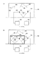
従来において、筐体、構造物、造営物等の電磁的なシールド効果を測定する代表的な方法として、IEEE(Institute of Electrical and Electronic Engineers)std299やIEC(International Electrotechnical Commission)61000−5−7が知られている。従来のシールド効果の測定方法の全体構成図を図8(a)および図8(b)に示す。図8(a)および図8(b)において、送信アンテナ100と、受信アンテナ101と、送信部102と、受信部103と、建物104と、シールド効果を有するシールド(遮蔽構造)を備えた被測定物105とが示されている。なお、図8(a)は被測定物105が無い場合における電磁界の測定形態(参照測定:リファレンス)であり、図8(b)は被測定物105がある場合の測定形態を示している。
Conventionally, IEEE (Institute of Electrical and Electronic Engineers) std299 and IEC (International Electrotechnical Commission) 61000-5-7 are typical methods for measuring the electromagnetic shielding effect of housings, structures, and structures. Are known. The whole block diagram of the conventional measuring method of the shield effect is shown to Fig.8 (a) and FIG.8 (b). 8A and 8B, a transmitting
被測定物105の電磁的なシールド効果を測定する場合、送信アンテナ100から電波(電磁波)を送信し、その電波を受信アンテナ101で受信することを基体としている。このシールド効果は、シールドがある場合とない場合の受信電力(もしくは電界強度・磁界強度)の差から定義され、筐体のシールド効果(SE)は以下のように与えられる。
When measuring the electromagnetic shielding effect of the
SE=P1−P2 (1)
もしくは
SE=E1−E2 (2)
ここで、P1とP2はシールドがある場合とない場合における受信電力(dBm)であり、E1とE2はシールドがある場合とない場合における受信電界強度(dBμV/m)である。なお、受信電力(もしくは電界強度や磁界強度)は受信アンテナ101の高さやその位置によって変化し、しかもシールドがある場合とない場合では、単純に電磁界が減少するものではない特徴がある。
SE = P 1 −P 2 (1)
Or SE = E 1 −E 2 (2)
Here, P 1 and P 2 are received power (dBm) with and without a shield, and E 1 and E 2 are received electric field strengths (dB μV / m) with and without a shield. The received power (or electric field strength or magnetic field strength) varies depending on the height of the
すなわち、受信アンテナ101の配置によっては、シールドがない場合に電界強度が最大となる一方、シールドがある場合、電磁波107の反射や吸収、散乱などの拡散成分106により受信電力が最小になるなどの現象が発生することがある。このため、受信アンテナ101の位置によってはシールド効果が増減することがあり、場合によって数dB〜10数dB程度も変動することがある(非特許文献1、非特許文献2を参照)。
しかしながら、従来のシールド効果の測定では、シールドがある場合とない場合における受信電力もしくは受信電界強度の差からシールド効果を規定するものであった。このため、シールド効果を測定する場合、2回同様な測定を実施する必要があった。 However, in the conventional measurement of the shield effect, the shield effect is defined from the difference in received power or received electric field strength with and without a shield. For this reason, when measuring the shielding effect, it was necessary to perform the same measurement twice.
また、参照測定で得られる結果は、周辺構造物などからの反射や吸収の影響を受けることから、シールド効果の測定結果に誤差が含まれてしまう。 Moreover, since the result obtained by the reference measurement is affected by reflection and absorption from surrounding structures and the like, an error is included in the measurement result of the shield effect.
また、大型の構造物の形態を有するシールド構造物の建築工事が完成している場合に、このシールド構造物のシールド効果を評価するには、このシールド構造物が建築される前の条件で電磁界測定をすることが現実的には困難であった。 In addition, when the construction of a shield structure having a large structure is completed, in order to evaluate the shield effect of this shield structure, the electromagnetic conditions under the condition before this shield structure is built are used. It was actually difficult to measure the field.
このような課題に鑑み、本発明は、参照測定をすることなく被測定物の電磁シールド効果を測定することができ、被測定物のシールド効果を容易に評価することができる電磁シールド効果測定システムおよびその方法を提供する。 In view of such a problem, the present invention can measure the electromagnetic shielding effect of an object to be measured without performing a reference measurement, and can easily evaluate the shielding effect of the object to be measured. And a method thereof.
請求項1に記載の本発明は、被測定物のシールド効果を測定するための電磁シールド効果測定システムであって、前記被測定物の内部に配置され前記測定に用いる電波を送信するための送信アンテナと、前記送信アンテナが前記電波を送信するための高周波信号を前記送信アンテナに給電する送信手段と、前記被測定物のシールド外部に配置され前記送信アンテナから送信された前記電波を受信するための受信アンテナと、前記受信アンテナに接続され前記受信した電波を検波して受信信号を出力する受信手段と、前記送信アンテナと前記受信アンテナとの間における前記被測定物が存在しない場合の前記電波の減衰量を基準値として記憶する基準値データベースと、前記受信手段から出力される受信信号の値と前記基準値とに基づいて演算を行い前記被測定物の前記シールド効果を求めるための測定結果演算手段と、を備える。 The present invention according to claim 1 is an electromagnetic shielding effect measuring system for measuring a shielding effect of an object to be measured, and is a transmission for transmitting a radio wave arranged inside the object to be measured and used for the measurement. An antenna, a transmission means for feeding a high-frequency signal for transmitting the radio wave to the transmission antenna, and the radio wave transmitted from the transmission antenna disposed outside the shield of the device under test. Receiving antenna, receiving means connected to the receiving antenna for detecting the received radio wave and outputting a received signal, and the radio wave when the device under test does not exist between the transmitting antenna and the receiving antenna Calculation based on a reference value database that stores the attenuation amount of the signal as a reference value, the value of the received signal output from the receiving means, and the reference value Comprises a measurement result calculating unit for determining the shielding effect of the carried device under test, the.
また、請求項2に記載の本発明は、請求項1において、前記送信手段から送信される前記電波の送信周波数と、前記受信手段が受信する受信周波数とを同期して同期検波測定を行うための周波数同期手段を備える。
Further, the present invention according to
また、請求項3に記載の本発明は、請求項1または2のいずれかにおいて、前記送信アンテナの入力部と前記受信アンテナの出力部とのうちのいずれか一方あるいは両方に前記電波を増幅するための増幅器が挿入されている。 In addition, according to a third aspect of the present invention, in any one of the first or second aspects, the radio wave is amplified to one or both of an input unit of the transmitting antenna and an output unit of the receiving antenna. An amplifier is inserted.
また、請求項4に記載の本発明は、前記減衰量は、請求項1〜3のいずれかにおいて、すくなくとも、前記送信アンテナのアンテナファクタ、前記受信アンテナのアンテナファクタ、ケーブル損失のうちのいずれかを含む。 According to a fourth aspect of the present invention, in the present invention, in any one of the first to third aspects, the attenuation is at least one of an antenna factor of the transmitting antenna, an antenna factor of the receiving antenna, and a cable loss. including.
また、請求項5に記載の本発明は、被測定物のシールド効果を測定するための電磁シールド効果測定方法であって、前記被測定物の内部に配置され前記測定に用いる電波を送信するための送信アンテナを前記被測定物の前記内部に配置し、前記送信アンテナが前記電波を送信するための高周波信号を前記送信アンテナに給電する送信手段により前記アンテナに前記高周波信号を給電し、前記被測定物のシールド外部に配置され前記送信アンテナから送信された前記電波を受信するための受信アンテナにより前記電波を受信し、前記受信アンテナに接続され前記受信した電波を検波して受信信号を出力する受信手段により前記受信信号を出力し、前記送信アンテナと前記受信アンテナとの間における前記被測定物が存在しない場合の前記電波の減衰量を基準値として記憶する基準値データベースにより前記減衰量を基準値として記憶しておき、前記受信手段から出力される受信信号の値と前記基準値とに基づいて演算を行い前記被測定物の前記シールド効果を求めるための測定結果演算手段により前記シールド効果を求める。
Further, the present invention according to
また、請求項6に記載の本発明は、請求項5において、前記送信手段から送信される前記電波の送信周波数と、前記受信手段が受信する受信周波数とを同期して同期検波測定を行うための周波数同期手段を用いる。 According to a sixth aspect of the present invention, in the fifth aspect, the synchronous detection measurement is performed in synchronization with the transmission frequency of the radio wave transmitted from the transmission unit and the reception frequency received by the reception unit. The frequency synchronization means is used.
また、請求項7に記載の本発明は、請求項5または6のいずれかにおいて、前記送信アンテナの入力部と前記受信アンテナの出力部とのうちのいずれか一方あるいは両方に前記電波を増幅するための増幅器が挿入されている。 According to a seventh aspect of the present invention, in any one of the fifth or sixth aspects, the radio wave is amplified to one or both of an input unit of the transmitting antenna and an output unit of the receiving antenna. An amplifier is inserted.
また、請求項8に記載の本発明は、請求項5〜7のいずれかにおいて、前記減衰量は、すくなくとも、前記送信アンテナのアンテナファクタ、前記受信アンテナのアンテナファクタ、ケーブル損失のうちのいずれかを含む。
The present invention according to
本発明によれば、参照測定をすることなく被測定物の電磁シールド効果を測定することができ、被測定物のシールド効果を容易に評価することができる電磁シールド効果測定システムおよびその方法を提供することができる。 According to the present invention, there is provided an electromagnetic shielding effect measuring system and method capable of measuring the electromagnetic shielding effect of the object to be measured without performing a reference measurement and easily evaluating the shielding effect of the object to be measured. can do.
<第1の実施の形態>
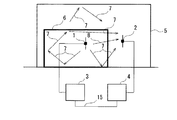
本発明のシールド測定システムおよびその方法の第1の実施の形態に係るシールド測定システムの全体構成図を図1に示す。この図1には、電磁シールド効果の測定に用いる電磁波(電波)を送信するための送信アンテナ1と、この送信アンテナ1から送信された電磁波を受信するための受信アンテナ2と、送信アンテナ1に接続されて電磁波を送信するための元となる高周波信号を出力する送信機3と、受信アンテナ2に接続されて送信アンテナ1から送信される電磁波を受信して検波し電気信号として出力するための受信機4と、電磁シールド効果の測定対象物である被測定物6と、この被測定物6が収容されている建物5と、が示されている。
<First Embodiment>
FIG. 1 shows an overall configuration diagram of a shield measurement system according to a first embodiment of the shield measurement system and method of the present invention. FIG. 1 shows a transmission antenna 1 for transmitting an electromagnetic wave (radio wave) used for measuring the electromagnetic shielding effect, a
また、送信アンテナ1は被測定物6の内部に配置され、被測定物6が有する電磁波に対するシールド効果が発揮される内部位置が選択されている。送信機3は、送信アンテナ1に電磁波を送信させるための高周波信号を供給する送信部25と、送信部25が送信する電磁波のレベルや周波数および波形などを設定し制御するための送信制御部26と、この送信制御部26に電磁波の送信条件などを入力して設定するための送信条件設定部27と、この送信条件設定部27を外部の図示しない機器と接続するための外部インタフェイス28を有している。
Further, the transmitting antenna 1 is disposed inside the device under
また、受信機4は、受信アンテナ2が受信した電磁波を検波して電気信号に変換するための受信部20と、受信部20から出力された電気信号に基づいて被測定物6の電磁シールド効果を演算すると共に受信部20の動作制御を行う演算制御部21と、演算制御部21に接続されて演算に必要な基準値を記憶している基準値データベース22と、演算制御部21にて演算した結果を測定値として外部へ出力する測定値出力部23と、測定値出力部23に接続され外部の図示しない機器と接続するための外部インタフェイス24とを有している。
The
本発明の第1の実施の形態では、被測定物6の電磁シールド効果を測定するために、従来の技術で要していた参照測定(リファレンス値の測定)を行うことなく、この参照測定値に代えて基準値データベース22に記憶された値に基づいて、演算制御部21で演算された値を用いる。この演算を行うために基準値データベース22に記憶される値は、電磁波の空間伝搬に伴う伝搬損失と、送信アンテナ1と受信アンテナ2のそれぞれ固有のアンテナファクタと、送信アンテナ1と受信アンテナ2の距離と、必要に応じて任意に設定される補正値とがすくなくとも含まれている。
In the first embodiment of the present invention, the reference measurement value is measured without performing the reference measurement (measurement of the reference value) required in the prior art in order to measure the electromagnetic shielding effect of the
ここで、基準値データベース22に記憶された値を用いて演算制御部21で演算される内容について説明する。まず、送信アンテナ1や受信アンテナ2による固有の影響を除いた、電磁波の空間伝搬のみに伴う伝搬損失である正規化サイト減衰量は、式(1)を用いて以下のように定義される。
Here, contents calculated by the
NSA=P1−P2−(AF1−AF2)−ΔAT・T (3)
式(3)はシールドがある場合の正規化サイト減衰量であり、また、AF1とAF2は、それぞれ送信アンテナ1と受信アンテナ2の損失を示すアンテナファクタ(dB)である。また、ΔAT・Tは相互インピーダンス補正係数(dB)である。なお、ΔAT・Tは周囲環境によって変化することがある。
NSA = P 1 −P 2 − (AF 1 −AF 2 ) −ΔA T · T (3)
Equation (3) is the normalized site attenuation when there is a shield, and AF 1 and AF 2 are antenna factors (dB) indicating the losses of the transmitting antenna 1 and the receiving
ここで、送信アンテナ1と受信アンテナ2との離隔が測定に使用する電磁波の波長より十分に長い場合、自由空間の場合の正規化サイト減衰量は、アンテナをダイボールアンテナとして仮定できる場合において、以下のように近似的に与えることができる。

上記の式(4)において、Rは送信アンテナ1と受信アンテナ2の離間した距離を示しており、kは波数(2π/f)である。従って正規化サイト減衰量は距離の関数になる。なお、fMは周波数(MHz)であり、Eは電界強度である。また、式(4)において「39.79」の値は「A Mixed Model for the Determination of Normalized Site Attenuation in OATS:IEEE TRANSACTIONS ON ELECTROMAGNETIC COMPATIBILITY, VOL. 43, NO. 1, pp.29-36,FEBRUARY 2001より」に基づく定数である。
In the above formula (4), R represents the distance between the transmitting antenna 1 and the receiving
式(1)では、シールド効果をシールドがある場合とない場合の電力もしくは電界強度の差分で定義したが、ここでは式(3)と式(4)で示される正規化サイト減衰量を用いて規定することを前提として、以下のようにシールド効果を定義する。 In Equation (1), the shielding effect is defined as the difference between the electric power or the electric field strength with and without the shield. Here, the normalized site attenuation shown in Equation (3) and Equation (4) is used. Assuming that it is specified, the shielding effect is defined as follows.
SE=NSA−NSAfree (5)
この式(5)の物理的な意味は、送信アンテナ1が自由空間に存在するときの伝播減衰量と、送信アンテナ2の周囲においてシールドや周辺環境が存在する時の伝播減衰量との差を示すものである。
SE = NSA-NSA free (5)
The physical meaning of this equation (5) is the difference between the propagation attenuation when the transmission antenna 1 exists in free space and the propagation attenuation when there is a shield or surrounding environment around the
式(1)の場合、シールド効果が参照測定結果に依存し、シールド効果の評価値が大きく変動する一方、式(5)の場合はその問題が回避できる利点がある。さらに、既にシールドが建設されている場合においても、そのシールド効果を評価することができる利点がある。なお、式(5)においてNSAfreeの代わりに半無限空間に対するNSA(半無限空間)を用いることもできる。 In the case of the formula (1), the shield effect depends on the reference measurement result, and the evaluation value of the shield effect largely fluctuates. On the other hand, the formula (5) has an advantage that the problem can be avoided. Furthermore, even when a shield has already been constructed, there is an advantage that the shielding effect can be evaluated. It should be noted that NSA (semi-infinite space) for semi-infinite space can be used instead of NSA free in equation (5).
図2には、本発明の第1の実施の形態による電磁シールド効果の測定を説明するための説明図を示す。建物5の内部に電磁シールド効果の測定を実施される被測定物6が設置されている。この被測定物は大型のシールドルームなどの建築物などが想定される。大型であるが故に、既に設置されている場合は電磁シールド効果の測定のために容易に移動することは困難な状況にある。
FIG. 2 is an explanatory diagram for explaining the measurement of the electromagnetic shielding effect according to the first embodiment of the present invention. An object to be measured 6 for measuring the electromagnetic shielding effect is installed inside the
この被測定物6の内部には、電磁シールド効果の測定に用いられる電磁波(電波)を放射するための送信アンテナ1が配置されている。この送信アンテナ1には、送信機3から高周波信号が印加されている。送信アンテナ1からは電磁波8が放射(送信)され、被測定物6のシールド効果を有する壁を透過して受信アンテナ2へ到達する。また、送信アンテナ1から送信される電磁波8は、直接に受信アンテナ2へ到達する以外に、被測定物6の内部で壁面に反射して拡散する拡散成分7も存在している。この拡散成分7は、被測定物6の内部で多重反射を行い、あるいは被測定物6の壁を透過して建物5の壁でも反射を生じる。これらの反射により、電磁波8に対して時間的な遅れや位相のずれ、周波数成分の変化などが生じる。これらの拡散成分7も受信アンテナ2にて電磁波8とともに受信される。
A transmitting antenna 1 for radiating electromagnetic waves (radio waves) used for measuring the electromagnetic shielding effect is disposed inside the device under
受信機4では、受信アンテナ2で受信した電磁波8および拡散成分7を検波して受信信号として取得する。取得した受信信号の値に対して、図1に示した演算制御手段21により所定の演算を行い、測定値出力部23に被測定物6の電磁シールド効果の測定結果を出力する。
In the
<第2の実施の形態>
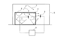
図3に、本発明の第2の実施の形態に係る電磁シールド測定システムおよびその方法による全体構成図を示す。この図3に示す構成においては、送信機3と受信機4を同期して動作させ、受信機4にて同期検波して正規化サイト減衰量を測定するものである。
<Second Embodiment>
FIG. 3 shows an overall configuration diagram of an electromagnetic shield measurement system and method according to a second embodiment of the present invention. In the configuration shown in FIG. 3, the
送信機3と受信機4とは制御ケーブル15にて互いが連結されている。この制御ケーブル15は、図1にて示した送信機3が備える外部インタフェイス28と、受信機4が備える外部インタフェイス24とを連結している。この制御ケーブル15を介して送信機3と受信機4とが互いに制御情報を交換して同期した動作を行う。送信機3から送出される高周波信号の周波数と受信機4が受信する電波の周波数とを同期して、被検体6の電磁シールド効果の測定を行うことができる。
The
<第3の実施の形態>
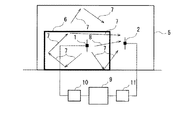
図4に、第3の実施の形態に係る電磁シールド効果測定システムおよびその方法による全体構成図を示す。この図4に示す構成においては、送信機3と受信機4の機能を一体化したネットワークアナライザなどの同期検波装置9を用いて正規化サイト減衰量を測定するものである。
<Third Embodiment>
FIG. 4 shows an overall configuration diagram of the electromagnetic shielding effect measuring system and method according to the third embodiment. In the configuration shown in FIG. 4, the normalized site attenuation is measured using a synchronous detector 9 such as a network analyzer in which the functions of the
この場合は、同期検波装置9の構成として、図1に示した送信機3と受信機4を一台にまとめている。この同期検波装置9の構成によって、送信と受信を同期した周波数で行う電磁シールド効果の測定が可能になる。送信機3と受信機4とを別々に用意する必要がなくなるので、簡便であり、送信機3と受信機4にそれぞれ固有の特性が予めわかっているので、精度よく電磁シールド効果の測定を行うことが可能になる。
In this case, as the configuration of the synchronous detection device 9, the
<第4の実施の形態>
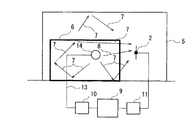
図5に、第4の実施の形態に係る電磁シールド効果測定システムおよびその方法による全体構成図を示す。この図5に示す構成においては、既に説明した第3の実施の形態の構成に対して、電磁シールド効果の測定のダイナミックレンジを拡大するために、増幅器10および増幅器11を挿入したものである。
<Fourth embodiment>
FIG. 5 shows an overall configuration diagram of the electromagnetic shielding effect measuring system and method according to the fourth embodiment. In the configuration shown in FIG. 5, the
増幅器10を送信アンテナ1と同期検波装置9との間に配置して、送信する電磁波の強度を増幅する。また、受信アンテナ2と同期検波装置9との間に増幅器11を配置して、受信アンテナ2で受信した電磁波を増幅する。このように、送信と受信でそれぞれ信号を増幅することにより、ノイズ成分との比(S/N比)が大きくなり、結果として電磁シールド効果の測定値のダイナミックレンジの拡大を実現することができる。
The
<第5の実施の形態>
図6に、第5の実施の形態に係る電磁シールド効果測定システムおよびその方法による全体構成図を示す。この図6に示す構成においては、電気/光変換器12と、球状ダイポールアンテナ14と、光ファイバケーブル13と、同期検波装置9と、受信アンテナ2とですくなくとも構成されている。
<Fifth embodiment>
FIG. 6 shows an overall configuration diagram of the electromagnetic shielding effect measuring system and method according to the fifth embodiment. In the configuration shown in FIG. 6, the electrical / optical converter 12, the
同期検波装置9から出力された高周波信号は、電気/光変換器12に入力されて光信号に変換される。この光信号は、光ファイバケーブル13を介して球状ダイポールアンテナ14へ入力される。球状ダイポールアンテナ14は水平偏波では無指向性を示し、垂直偏波で8の字特性を有するので、理論値に近いより高精度の電磁シールド効果の測定が可能である。
The high frequency signal output from the synchronous detector 9 is input to the electrical / optical converter 12 and converted into an optical signal. This optical signal is input to the
球状ダイポールアンテナ14に入力された光信号は、球状ダイポールアンテナ14の内部に配置された図示しない光/電気信号変換器により電気信号に戻され、増幅装置により増幅された後に、アンテナ内部の給電点に供給される。また、球状ダイポールアンテナ14は、内部に図示しない電源を備えており、被測定物6の内部には光ファイバケーブル13が引き込まれるのみである。このため、同軸ケーブルなどによる電磁波の漏洩や散乱を抑制したシールド効果を評価することが可能となり、特にシールド効果が高い状況では有利な測定方法となる。
The optical signal input to the
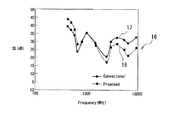
なお、図7に示すのは、縦3m×横3m×高さ2.5mの鉄板で構成されたシールドルームのシールド効果の測定結果16である。この図7において、実線17は従来法による測定結果であり、破線18は本発明の第1〜第5の実施の形態に示した電磁シールド効果測定システムおよびその方法を用いた測定結果である。
In addition, what is shown in FIG. 7 is the
以上説明した本発明の実施の形態の構成により、参照測定を実施する必要がなくなり測定の効率化が図られるとともに、既設のシールドに対するシールド効果の評価や、さらにシールド効果のメンテナンスを実施することが可能となる。シールド効果は周波数によって変化するが、図7に示した測定結果16に参照されるように、従来法を示す実線17と本発明を示す破線18とのシールド効果の測定結果の差は、概ね6〜8dB以下であることがわかる。通常、シールド効果のばらつきは10数dB程度あることを鑑みると、本発明による電磁シールド効果測定システムおよびその方法は、従来の測定法と同様の測定精度および信頼性を得られることがわかる。
With the configuration of the embodiment of the present invention described above, it is not necessary to perform reference measurement, and the efficiency of the measurement can be achieved, and the shield effect can be evaluated for the existing shield and further the shield effect can be maintained. It becomes possible. Although the shielding effect varies depending on the frequency, as shown in the
1 送信アンテナ
2 受信アンテナ
3 送信機
4 受信機
5 建物
6 被測定物
7 拡散成分
8 電磁波
9 同期検波装置
20 受信部
21 演算制御部
22 基準値データベース
23 測定値出力部
24、28 外部インタフェイス
25 送信部
26 送信制御部
27 送信条件設定部
DESCRIPTION OF SYMBOLS 1
Claims (8)
前記被測定物の内部に配置され前記測定に用いる電波を送信するための送信アンテナと、
前記送信アンテナが前記電波を送信するための高周波信号を前記送信アンテナに給電する送信手段と、
前記被測定物のシールド外部に配置され前記送信アンテナから送信された前記電波を受信するための受信アンテナと、
前記受信アンテナに接続され前記受信した電波を検波して受信信号を出力する受信手段と、
前記送信アンテナと前記受信アンテナとの間における前記被測定物が存在しない場合の前記電波の減衰量を基準値として記憶する基準値データベースと、
前記受信手段から出力される受信信号の値と前記基準値とに基づいて演算を行い前記被測定物の前記シールド効果を求めるための測定結果演算手段と、
を備えることを特徴とする電磁シールド効果測定システム。 An electromagnetic shielding effect measuring system for measuring a shielding effect of a measured object,
A transmitting antenna for transmitting a radio wave disposed in the object to be measured and used for the measurement;
Transmitting means for feeding a high-frequency signal for transmitting the radio wave by the transmitting antenna to the transmitting antenna;
A receiving antenna for receiving the radio wave transmitted from the transmitting antenna and disposed outside the shield of the device under test;
Receiving means connected to the receiving antenna for detecting the received radio wave and outputting a received signal;
A reference value database that stores, as a reference value, an attenuation amount of the radio wave when the device under test does not exist between the transmitting antenna and the receiving antenna;
A measurement result calculating means for calculating the shield effect of the device under test based on the value of the received signal output from the receiving means and the reference value;
An electromagnetic shielding effect measuring system comprising:
すくなくとも、前記送信アンテナのアンテナファクタ、前記受信アンテナのアンテナファクタ、ケーブル損失のうちのいずれかを含むことを特長とする請求項1〜3のいずれかに記載の電磁シールド効果測定システム。 The amount of attenuation is
The electromagnetic shielding effect measuring system according to any one of claims 1 to 3, further comprising at least one of an antenna factor of the transmitting antenna, an antenna factor of the receiving antenna, and a cable loss.
前記被測定物の内部に配置され前記測定に用いる電波を送信するための送信アンテナを前記被測定物の前記内部に配置し、
前記送信アンテナが前記電波を送信するための高周波信号を前記送信アンテナに給電する送信手段により前記アンテナに前記高周波信号を給電し、
前記被測定物のシールド外部に配置され前記送信アンテナから送信された前記電波を受信するための受信アンテナにより前記電波を受信し、
前記受信アンテナに接続され前記受信した電波を検波して受信信号を出力する受信手段により前記受信信号を出力し、
前記送信アンテナと前記受信アンテナとの間における前記被測定物が存在しない場合の前記電波の減衰量を基準値として記憶する基準値データベースにより前記減衰量を基準値として記憶しておき、
前記受信手段から出力される受信信号の値と前記基準値とに基づいて演算を行い前記被測定物の前記シールド効果を求めるための測定結果演算手段により前記シールド効果を求めることを特徴とする電磁シールド効果測定方法。 An electromagnetic shielding effect measuring method for measuring a shielding effect of an object to be measured,
A transmitting antenna for transmitting a radio wave used for the measurement arranged inside the device under test is arranged inside the device under test;
The transmission antenna feeds the high-frequency signal to the antenna by transmission means that feeds the transmission antenna with a high-frequency signal for transmitting the radio wave,
Receiving the radio wave by a receiving antenna for receiving the radio wave transmitted from the transmitting antenna disposed outside the shield of the object to be measured;
The reception signal is output by reception means connected to the reception antenna and detecting the received radio wave and outputting a reception signal;
The attenuation amount is stored as a reference value by a reference value database that stores the attenuation amount of the radio wave when the measured object does not exist between the transmitting antenna and the receiving antenna as a reference value,
An electromagnetic wave characterized in that the shielding effect is obtained by a measurement result computing means for performing computation based on a value of a received signal output from the receiving means and the reference value and obtaining the shielding effect of the device under test. Shield effect measurement method.
すくなくとも、前記送信アンテナのアンテナファクタ、前記受信アンテナのアンテナファクタ、ケーブル損失のうちのいずれかを含むことを特長とする請求項5〜7のいずれかに記載の電磁シールド効果測定方法。
The amount of attenuation is
The electromagnetic shielding effect measuring method according to any one of claims 5 to 7, including at least one of an antenna factor of the transmitting antenna, an antenna factor of the receiving antenna, and a cable loss.
Priority Applications (1)
| Application Number | Priority Date | Filing Date | Title |
|---|---|---|---|
| JP2004111378A JP2005292088A (en) | 2004-04-05 | 2004-04-05 | Electromagnetic shield effect measuring system and method |
Applications Claiming Priority (1)
| Application Number | Priority Date | Filing Date | Title |
|---|---|---|---|
| JP2004111378A JP2005292088A (en) | 2004-04-05 | 2004-04-05 | Electromagnetic shield effect measuring system and method |
Publications (1)
| Publication Number | Publication Date |
|---|---|
| JP2005292088A true JP2005292088A (en) | 2005-10-20 |
Family
ID=35325161
Family Applications (1)
| Application Number | Title | Priority Date | Filing Date |
|---|---|---|---|
| JP2004111378A Pending JP2005292088A (en) | 2004-04-05 | 2004-04-05 | Electromagnetic shield effect measuring system and method |
Country Status (1)
| Country | Link |
|---|---|
| JP (1) | JP2005292088A (en) |
Cited By (3)
| Publication number | Priority date | Publication date | Assignee | Title |
|---|---|---|---|---|
| CN116466174A (en) * | 2023-05-23 | 2023-07-21 | 奇瑞新能源汽车股份有限公司 | An electromagnetic compatibility darkroom test path verification system and method |
| JP2023136741A (en) * | 2022-03-17 | 2023-09-29 | Tdk株式会社 | Electromagnetic wave testing device and electromagnetic wave testing method |
| CN119805004A (en) * | 2025-01-08 | 2025-04-11 | 南京青析技术有限公司 | Ultra-wide spectrum electromagnetic shielding effectiveness measurement device and method |
-
2004
- 2004-04-05 JP JP2004111378A patent/JP2005292088A/en active Pending
Cited By (4)
| Publication number | Priority date | Publication date | Assignee | Title |
|---|---|---|---|---|
| JP2023136741A (en) * | 2022-03-17 | 2023-09-29 | Tdk株式会社 | Electromagnetic wave testing device and electromagnetic wave testing method |
| JP7789595B2 (en) | 2022-03-17 | 2025-12-22 | Tdk株式会社 | Electromagnetic wave testing device and electromagnetic wave testing method |
| CN116466174A (en) * | 2023-05-23 | 2023-07-21 | 奇瑞新能源汽车股份有限公司 | An electromagnetic compatibility darkroom test path verification system and method |
| CN119805004A (en) * | 2025-01-08 | 2025-04-11 | 南京青析技术有限公司 | Ultra-wide spectrum electromagnetic shielding effectiveness measurement device and method |
Similar Documents
| Publication | Publication Date | Title |
|---|---|---|
| US10819446B2 (en) | Radar transmitting power and channel performance monitoring apparatus | |
| US9859999B2 (en) | Shielding attenuation measurement | |
| JPWO2006075584A1 (en) | Electromagnetic field distribution measuring method and apparatus, computer program, and information recording medium | |
| KR20200132023A (en) | Electric Field Intensity Measuring Method of EMP Permeating Facility Area | |
| CN104849592A (en) | Radio telescope broadband electromagnetic shielding effectiveness detection system and detection method thereof | |
| Gu et al. | Analysis and experiment on the modulation sensitivity of Doppler radar vibration measurement | |
| CN102025433A (en) | Signal detection method, detection device and detection base station | |
| CN108925143B (en) | Standing wave detection method, standing wave detection device and electron gun | |
| JP2005292088A (en) | Electromagnetic shield effect measuring system and method | |
| CN109254207B (en) | A kind of cable electromagnetic radiation analysis method and system | |
| Eser et al. | Open-area test site (OATS) calibration | |
| US8022713B2 (en) | Method for measuring antenna characteristics out operational frequency range of chamber | |
| CN204613328U (en) | A kind of radio telescope wideband electromagnetic shield effectiveness detection system | |
| JP2019074422A (en) | Wireless receiver, method for wireless reception, and wireless system | |
| US7309982B2 (en) | Portable system for rapid characterization of electrical properties of a material | |
| JP2021119332A (en) | Radio signal generation location estimation method | |
| JP7451975B2 (en) | Electromagnetic wave measurement device and electromagnetic wave measurement method | |
| JP5373339B2 (en) | Wireless tag distance measuring device | |
| CN208337581U (en) | A kind of optical fiber detector based on distributed vector network analyzer | |
| JP3809528B2 (en) | Terminal position detection method and terminal position detection system | |
| TWI429922B (en) | Non-contact measurement method for electromagnetic interference | |
| US12489536B2 (en) | Method and system for determining area in which attenuation object is located | |
| Kayano et al. | Experimental and Theoretical Studies on Communicable Distance for Medical Telemeters between Hospitals Located with a Distance of 1,300 Meters | |
| JPS61260109A (en) | Measuring instrument for concrete thickness | |
| JPH06347497A (en) | Evaluation testing device of antenna |