JP2005292067A - Optical element and optical system measuring apparatus - Google Patents
Optical element and optical system measuring apparatus Download PDFInfo
- Publication number
- JP2005292067A JP2005292067A JP2004110707A JP2004110707A JP2005292067A JP 2005292067 A JP2005292067 A JP 2005292067A JP 2004110707 A JP2004110707 A JP 2004110707A JP 2004110707 A JP2004110707 A JP 2004110707A JP 2005292067 A JP2005292067 A JP 2005292067A
- Authority
- JP
- Japan
- Prior art keywords
- light
- wavelength
- wavefront
- measurement
- diffraction grating
- Prior art date
- Legal status (The legal status is an assumption and is not a legal conclusion. Google has not performed a legal analysis and makes no representation as to the accuracy of the status listed.)
- Withdrawn
Links
Images


Landscapes
- Instruments For Measurement Of Length By Optical Means (AREA)
- Testing Of Optical Devices Or Fibers (AREA)
Abstract
【課題】 シアリング干渉計を、その長所を活かしてEUV光学系の測定に用いる場合、EUV光学系の測定ニーズであるチルト波面が計れないことは大きな問題であった。
【解決手段】 回折格子を用いたシアリング干渉計測装置において、使用波長が同じでピッチの異なる回折格子を二種類以上と、前記使用波長と異なる第二の使用波長用の回折格子を少なくとも一種類を同一の基板、または、同一の支持体上に構成したことを特徴とする。
【選択図】 図1
PROBLEM TO BE SOLVED: To use a shearing interferometer for measurement of an EUV optical system taking advantage of its advantages, it is a big problem that a tilt wavefront which is a measurement need of the EUV optical system cannot be measured.
In a shearing interferometer using a diffraction grating, two or more types of diffraction gratings having the same used wavelength and different pitches, and at least one type of diffraction grating for a second used wavelength different from the used wavelength are used. It is characterized by being configured on the same substrate or the same support.
[Selection] Figure 1
Description
本発明は、光学系の出力波面の特性解析に用いられる波面測定器、位相分布測定器に係わり、特に非可視光波長域での光学素子の性能評価に係わる。 The present invention relates to a wavefront measuring device and a phase distribution measuring device used for characteristic analysis of an output wavefront of an optical system, and more particularly to performance evaluation of an optical element in a non-visible light wavelength region.
従来、光学系や光学素子の性能を評価するために、入射光に対する反射波面や透過波面を測定する干渉計が様々な形で開発され、用いられてきた。そのうちシアリング干渉計は、その構成部品が比較的簡易であることから、高度な構成部品が得られ難い波長の光学系の評価において、可能性が大きいと期待されている。 Conventionally, in order to evaluate the performance of optical systems and optical elements, interferometers that measure the reflected wavefront and transmitted wavefront of incident light have been developed and used in various forms. Among them, the shearing interferometer is expected to have great potential in the evaluation of optical systems having wavelengths where it is difficult to obtain advanced components because the components are relatively simple.
この一例は、近年開発が盛んになってきている、例えば特許文献1に開示があるようなEUV(極端紫外線)と呼ばれる軟X線領域の10nm程度の波長の投影光学装置であり、これを用いた50nmレベルの線幅の半導体露光装置の開発が計画され、進められている。充分な結像性能を確保するためには、少なくとも1/4波長以下の収差に光学系を管理する必要があり、EUV波長では、これが1nmレベルの極めて高精度なものである必要がある。 One example of this is a projection optical apparatus having a wavelength of about 10 nm in a soft X-ray region called EUV (extreme ultraviolet), which has been developed in recent years, as disclosed in Patent Document 1, for example. Development of a semiconductor exposure apparatus having a line width of about 50 nm has been planned and advanced. In order to ensure sufficient imaging performance, it is necessary to manage the optical system at least for aberrations of ¼ wavelength or less, and for the EUV wavelength, it is necessary to have an extremely high accuracy of 1 nm level.
これに対して、従来の、例えば、フィゾー干渉計や、マッハツェンダー干渉計を用いようとすると、参照光と測定光を分岐するためのフィゾーレンズや、ビームスプリッターに高精度、高効率のものが必要であるが、実際に使用できるレベルのものは、現時点では未だ確立していない。 On the other hand, when a conventional Fizeau interferometer or Mach-Zehnder interferometer is used, for example, a Fizeau lens for splitting the reference light and the measurement light, or a beam splitter with high accuracy and high efficiency are used. Although it is necessary, a practically usable level has not been established yet.
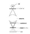
そこで、参照光と測定光を分岐する素子として、単純な回折格子を用いたシアリング干渉計が注目されている。図2は、このシアリング干渉計の基本的な構成を示す一例である。単一の光源から出射した光は、ピンホールを通過させることによって、空間的にコヒーレントな点光源となる。この光を被光学系に入射する。被検光学系を通過した光は、分岐用の回折格子を通過して、回折光を生じる。回折光は、進行方向の変わらない0次と、回折格子のピッチと光波長によって決まる回折角度方向へ±1次、±2次、というように、通常は、複数発生する。次の段の次数選択アパーチャーは、開口が、この例では、2つ設けてあり、±1次の回折光のみを透過させる。この±1次の回折光が、参照光と測定光に相当する光であり、CCDイメージセンサ上での強度検出によって、干渉によって位相情報が強度情報に変換され、すなわち干渉縞画像として、検出される。 Therefore, a shearing interferometer using a simple diffraction grating has attracted attention as an element for branching the reference light and the measurement light. FIG. 2 is an example showing the basic configuration of this shearing interferometer. Light emitted from a single light source passes through a pinhole, thereby becoming a spatially coherent point light source. This light is incident on the optical system. The light that has passed through the test optical system passes through the diffraction grating for branching to generate diffracted light. Usually, a plurality of diffracted lights are generated, such as a 0th order whose traveling direction does not change and a ± 1st order and a ± 2nd order in the diffraction angle direction determined by the pitch of the diffraction grating and the light wavelength. The order selection aperture of the next stage is provided with two openings in this example, and transmits only ± first-order diffracted light. This ± 1st-order diffracted light is light corresponding to reference light and measurement light, and phase information is converted into intensity information by interference by intensity detection on the CCD image sensor, that is, detected as an interference fringe image. The
図3はこのようにして測定された干渉縞画像の一例である。この場合には球面波の横方向に回折した±1次光を干渉させているため、基本成分として等間隔の縦縞が検出され、そして、例えば、図1(b)の場合には、球面収差の影響によって、縞が所謂、糸巻き型に歪んでいる。このような歪みを、よく知られた、干渉縞画像からの位相回復計算によって、参照光と測定光の位相差分布へ回復することで、被検光学系の波面情報、位相分布情報を検出することができる。 FIG. 3 is an example of an interference fringe image measured in this way. In this case, since ± 1st order light diffracted in the lateral direction of the spherical wave is caused to interfere, vertical stripes at equal intervals are detected as basic components. For example, in the case of FIG. As a result, the stripes are distorted into a so-called pincushion type. The wavefront information and phase distribution information of the optical system to be detected are detected by recovering such distortion to the phase difference distribution between the reference light and the measurement light by well-known phase recovery calculation from the interference fringe image. be able to.
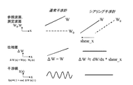
また、図4は、シアリング干渉計の参照光と測定光の関係を通常の干渉計と比較した模式的な説明図である。図上段は測定光の波面(以下、測定波面)Wと、参照光の波面(以下、参照波面)W0が位置xの関数として示されている。上にあると波面、即ち位相が進んでいることを示す。この例では、測定波面として、x方向にいくと波面が線形に進む、所謂チルト波面を表している。この場合、測定波面Wはxの一次関数である。この図に示されているように、通常干渉計では、参照波面は、測定波面とは独立な基準位相を持っているのに対し、シアリング干渉計では、参照波面と測定波面とは同じものを位置(この場合はx方向)に横ずらし(シア)しているだけである。これは、測定光自身を回折格子で分岐してコピーを作ったもの同士を干渉させているからである。 FIG. 4 is a schematic explanatory diagram comparing the relationship between the reference light and the measurement light of the shearing interferometer with a normal interferometer. In the upper part of the figure, the wavefront of measurement light (hereinafter referred to as measurement wavefront) W and the wavefront of reference light (hereinafter referred to as reference wavefront) W0 are shown as functions of position x. When it is above, it indicates that the wavefront, that is, the phase is advanced. In this example, a so-called tilt wavefront is shown in which the wavefront travels linearly in the x direction as the measurement wavefront. In this case, the measurement wavefront W is a linear function of x. As shown in this figure, in the normal interferometer, the reference wavefront has a reference phase independent of the measurement wavefront, whereas in the shearing interferometer, the reference wavefront and the measurement wavefront are the same. It is only laterally shifted (sheared) in the position (in this case, the x direction). This is because the measurement light itself is branched by a diffraction grating to interfere with each other.
図の中段には、干渉計で測定される位相差を示した。通常干渉計では位相差ΔWは一次関数であるのに対して、シアリング干渉計では、定数関数になっている。これは、自分自身を横ずらして差を取ったものは、微小横ずらしに大しては、一次微分にずらし量を乗じたものに近似できることに対応している。即ち、測定波面Wが一次関数であるので、その微分は定数関数になっている。 The middle part of the figure shows the phase difference measured by the interferometer. In the normal interferometer, the phase difference ΔW is a linear function, whereas in the shearing interferometer, it is a constant function. This corresponds to the fact that the difference obtained by laterally shifting itself can be approximated to the one obtained by multiplying the first derivative by the amount of shift, rather than the small lateral shift. That is, since the measurement wavefront W is a linear function, the differentiation is a constant function.
図の下段には、上記のような位相差がある場合の干渉縞画像を模式的に示してあり、通常干渉計の場合には、等間隔の三角関数の縞が現れ、シアリング干渉計の場合には縞は現れず、所謂ワンカラーと呼ばれる画面全体が単一の濃淡を表す画像となる。 The lower part of the figure schematically shows an interference fringe image when there is a phase difference as described above. In the case of a normal interferometer, equally spaced trigonometric fringes appear, and in the case of a shearing interferometer. No stripes appear in the image, and the entire screen, so-called one-color, becomes an image representing a single shade.
通常干渉計の場合には、三角関数の縞が現れるため、その周期を検出することが容易であり、この周期が測定波面の傾き(チルト量)、つまり、xに対する一次関数の係数と結びついている。よって、通常干渉計においては、容易にチルト波面のチルト量を測定することが可能である。一方、シアリング干渉計では、上述のように、チルト波面を測定した場合、その干渉縞画像に縞が現れないため、周期からチルト量を検出することができない。 In the case of a normal interferometer, since a trigonometric function fringe appears, it is easy to detect the period, and this period is linked to the inclination (tilt amount) of the measurement wavefront, that is, the coefficient of the linear function with respect to x. Yes. Therefore, the normal interferometer can easily measure the tilt amount of the tilt wavefront. On the other hand, in the shearing interferometer, when the tilt wavefront is measured as described above, no fringe appears in the interference fringe image, and therefore the tilt amount cannot be detected from the period.
この場合、チルト量は干渉縞のどこに現れているかというと、画像全体の明暗である。よって、画像全体の明暗を測定できれば、チルト量を測定できることになる。
しかしながら、この画像全体の明暗を測定することは実際には非常に困難である。なぜなら、この明暗は、干渉計の参照光と測定光の全体的な位相差そのものであって、測定系のごく小さな波長オーダのゆらぎなどによって、敏感に変動するものだからである。シアリング干渉計では、このことは、図2に示した回折格子の位置の、振動などによる微小な変動などに相当する。また、回折格子の位置を波長以下のオーダで正確に把握しなければ、絶対量としての位相差を検出することはできず、結局、参照光と測定光の全体的な位相差を測定することは非常に困難である。 However, it is actually very difficult to measure the brightness of the entire image. This is because this contrast is the overall phase difference between the reference light of the interferometer and the measurement light itself, and fluctuates sensitively due to fluctuations in the very small wavelength order of the measurement system. In the shearing interferometer, this corresponds to a minute fluctuation due to vibration or the like in the position of the diffraction grating shown in FIG. In addition, if the position of the diffraction grating is not accurately grasped on the order of the wavelength or less, the phase difference as an absolute amount cannot be detected, and eventually the overall phase difference between the reference light and the measurement light should be measured. Is very difficult.
なお、このような全体的な位相差のゆらぎについては、通常干渉計でも問題となる。これは、図4に示した三角関数状の干渉縞が、位置xに対して、変動することに相当する。このような変動は画像取得して、画像を元に位相回復する測定において、画像エラーとなり、問題となる。この問題に対しては、所謂、フリンジスキャンという技術が用いられて無害化されている。フリンジスキャンでは、積極的に全体的な位相差を変調して、その変調に基づく干渉縞の位置xに対する移動を測定することによって、高精度に干渉縞の形状、そして、そこから三角関数の周期などを検出することが可能となっている。 It should be noted that such an overall phase difference fluctuation is also a problem even in a normal interferometer. This corresponds to the fact that the trigonometric interference fringes shown in FIG. 4 vary with respect to the position x. Such a variation causes an image error and causes a problem in the measurement in which the image is acquired and the phase is recovered based on the image. This problem is rendered harmless by using a so-called fringe scan technique. In fringe scanning, the overall phase difference is positively modulated, and the movement of the interference fringe with respect to the position x based on the modulation is measured, so that the shape of the interference fringe and the period of the trigonometric function are accurately obtained therefrom. Etc. can be detected.
シアリング干渉計に対しても、この技術は有効であるが、それは一次関数であるチルト波面よりも高次の波面情報に関してであって、チルト波面では、逆に、全体位相を振られると、余計に全体位相がどこにあるのかがわからなくなってしまうという問題が生じてしまう。 This technique is also effective for shearing interferometers, but it relates to higher-order wavefront information than the tilt wavefront, which is a linear function. This causes a problem that it is impossible to know where the entire phase is.
以上述べたように、シアリング干渉計では、単純な回折格子によって、分岐が可能であり、EUV波長などに対して有効であるが、そのかわり、チルト波面のチルト量を高感度で検出することができないという問題点がある。 As described above, the shearing interferometer can be branched by a simple diffraction grating and is effective for the EUV wavelength. Instead, it can detect the tilt amount of the tilt wavefront with high sensitivity. There is a problem that it is not possible.
このような問題点に対して、EUVでの計測ニーズの例を図5を用いて示す。EUV光学系では、一般的に、反射ミラー光学系が用いられている。そして、垂直に近い角度範囲で反射ミラーを用いるために、干渉を利用した多層膜コーティングが施されている。このようなミラーにおいては、多層膜の干渉効果のために、反射光の位相が入射角度依存性を持つ。図5はこの様子を、反射率とともに、示した一例である。反射位相の変化は、使用範囲である、高反射率領域で最も急峻であることが示されており、これは線形応答の理論から複素感受率一般にいえる性質である。 FIG. 5 shows an example of measurement needs in EUV for such problems. In the EUV optical system, a reflection mirror optical system is generally used. And in order to use a reflective mirror in the angle range near perpendicular | vertical, the multilayer film coating using interference is given. In such a mirror, the phase of the reflected light has an incident angle dependency due to the interference effect of the multilayer film. FIG. 5 shows an example of this state together with the reflectance. The change in the reflection phase is shown to be the steepest in the high reflectivity region, which is the range of use, and this is a property that can generally be said to be a complex susceptibility from the theory of linear response.
従って、実際にEUV光学系で多層膜ミラーを用いる場合、このような急峻な反射位相変化を測定して、確認するというニーズがある。そして、この変化は入射角度に対する関数として見れば、一次成分が主成分であり、この一次成分を測定することが必要である。これは、前述のチルト波面と同じものを測定することに相当し、従って、シアリング干渉計では測定困難な成分に相当する。 Therefore, when a multilayer mirror is actually used in an EUV optical system, there is a need to measure and confirm such a steep reflection phase change. If this change is viewed as a function of the incident angle, the primary component is the main component, and it is necessary to measure this primary component. This corresponds to measuring the same tilt wavefront as described above, and thus corresponds to a component that is difficult to measure with a shearing interferometer.
このように、シアリング干渉計を、その長所を活かしてEUV光学系の測定に用いる場合、EUV光学系の測定ニーズであるチルト波面が計れないことは大きな問題であった。 As described above, when the shearing interferometer is used for measurement of the EUV optical system by taking advantage of the advantages thereof, it is a big problem that the tilt wavefront which is a measurement need of the EUV optical system cannot be measured.
本発明は以上述べてきた従来の技術の持つ問題点を解決するものであり、本発明のシアリング干渉計測装置は、使用波長が同じでピッチの異なる回折格子を二種類以上と、前記使用波長と異なる第二の使用波長用の回折格子を少なくとも一種類を同一の基板、または、同一の支持体上に構成し、光分岐素子としたことを特徴とする。 The present invention solves the problems of the prior art described above. The shearing interference measuring apparatus of the present invention includes two or more types of diffraction gratings having the same operating wavelength and different pitches, and the used wavelength. It is characterized in that at least one kind of diffraction gratings for different second used wavelengths is formed on the same substrate or the same support to form an optical branching element.
本発明により、簡易な構成でEUV波長などに使用できるシアリング干渉計においても、チルト波面のチルト量計測を行うことがことが可能となる。 According to the present invention, it is possible to measure the tilt amount of the tilt wavefront even in a shearing interferometer that can be used for EUV wavelengths or the like with a simple configuration.
先ず、本発明の第1の実施形態を説明する。本実施例は本発明の複数種類の回折格子を同一基板、支持体に構成したシアリング干渉計測装置を実施した一例である。 First, a first embodiment of the present invention will be described. This embodiment is an example in which a shearing interference measuring apparatus in which a plurality of types of diffraction gratings according to the present invention are configured on the same substrate and support is implemented.
まず、図1を用いて本実施例の測定装置の原理的構成について説明する。本実施例では、被検光学系に対して、2種類のEUV波長の光(λ1=13、4nm、λ2=12nm)を入射し、出射させる。この2つの光は被検光学系101をなるべく同様に通り、従って、なるべく同じ被測定情報を持つように配置される。 First, the basic configuration of the measuring apparatus of this embodiment will be described with reference to FIG. In this embodiment, two types of EUV wavelength light (λ1 = 13, 4 nm, λ2 = 12 nm) are incident on and emitted from the test optical system. The two lights pass through the test optical system 101 as much as possible, and are therefore arranged so as to have the same measurement information as much as possible.
被検光学系から出射した2つの被検光波1、2(102、103)はそれぞれ、図2で示したようなシアリング干渉を生じるように、分岐用の回折格子104に入射され、回折、干渉効果によって、複数の次数の回折光に分割され、続いて次数選択アパーチャー108で±1次光の2つの光波のみが透過される構成によって、CCDイメージセンサ109上まで達する光が選択される。CCDイメージセンサでは、±1次光が合わさった干渉強度を検出し、明暗の画像情報が得られる。 The two test light waves 1 and 2 (102, 103) emitted from the test optical system are incident on the branching diffraction grating 104 so as to cause shearing interference as shown in FIG. Due to the effect, the light reaching the CCD image sensor 109 is selected by a configuration in which the light is split into a plurality of orders of diffracted light and then only the two light waves of ± first order light are transmitted through the order selection aperture 108. The CCD image sensor detects the interference intensity combined with the ± first-order light and obtains light and dark image information.
分岐用の回折格子104では、2つの波長の被検光波1、2(102、103)に対して、それぞれ異なる領域が用意されており、特に光波1に関しては、これが回折格子面と交わる場所に2種類の異なるピッチ(p1=10μm、p2=12μm)の回折格子が形成されている。 In the diffraction grating 104 for branching, different regions are prepared for the test light waves 1 and 2 (102, 103) having two wavelengths, respectively, and particularly with respect to the light wave 1 at a place where it intersects the diffraction grating surface. Two types of diffraction gratings having different pitches (p1 = 10 μm, p2 = 12 μm) are formed.
また、光波2に関しては、これが回折格子面と交わる場所にはp3=9μmのピッチの回折格子が形成されている。
Further, with respect to the
図6に、このような本発明で使用される回折格子の代表的な例について、波長とピッチの関係をまとめて示した。図下部に条件A)として示したのは、±1次光の回折角度がほぼ同様になる条件であり、この条件は必須ではないが、図1に示す次数選択アパーチャーの2つのスリットの間隔が光波1と光波2でほぼ同等になる条件として、実用的に構成を簡易にするものとなっている。
FIG. 6 collectively shows the relationship between wavelength and pitch for typical examples of the diffraction grating used in the present invention. The condition A) shown in the lower part of the figure is a condition in which the diffraction angles of the ± first-order light are substantially the same. This condition is not essential, but the interval between the two slits of the order selection aperture shown in FIG. As a condition in which the light wave 1 and the
一方、条件B)は、同一波長様の回折格子ピッチについての条件であるが、これについては、以下の検出方法の説明で後述する。 On the other hand, the condition B) is a condition for the diffraction grating pitch of the same wavelength. This will be described later in the description of the detection method below.
次に、図1で示した本発明の原理的な構成を実現する全体配置の例を図7を用いて説明する。 Next, an example of the overall arrangement for realizing the principle configuration of the present invention shown in FIG. 1 will be described with reference to FIG.
図7(a)、(b)は、当該測定装置の構成を図中に示したxyzの直交座標系(zが光の全体的な進行方向)において、それぞれ、y方向から((a))、x方向から((b))、見た模式図である。 7 (a) and 7 (b) respectively show the configuration of the measurement apparatus from the y direction in the xyz orthogonal coordinate system (z is the overall traveling direction of light) ((a)). It is the schematic diagram seen from the x direction ((b)).
図7中、異なる波長の光を発する光源1(701)、光源2(702)から出射した光は、ピンホール703を通過して空間的に略コヒーレントな2つの点光源となり、当該2つの点光源からの光が被検光学系704へ入射する。 In FIG. 7, light emitted from the light source 1 (701) and the light source 2 (702) that emit light of different wavelengths passes through the pinhole 703 to become two spatially substantially coherent point light sources. Light from the light source enters the test optical system 704.
被検光学系704を通過して、光学系の位相情報を担った2波長の出射光は、次に、分岐用回折格子705へ入射され、複数の回折次数の回折光へ分割される。分岐用回折格子705は、前述した図6の構成となっている。 The two-wavelength outgoing light that has passed through the test optical system 704 and carried the phase information of the optical system is then incident on the branching diffraction grating 705 and divided into diffracted light of a plurality of diffraction orders. The branching diffraction grating 705 has the configuration shown in FIG.
それぞれ、次数選択アパーチャーを通過し、選択された±1次光はCCDイメージセンサ707上で干渉し、強度検出される。 Each of the light passes through the order selection aperture, and the selected ± 1st order light interferes on the CCD image sensor 707 and the intensity is detected.
本実施例の構成によれば、この干渉縞は光学系が無収差で点を点に理想結像する場合には、図1に示唆したように、x方向に周期的に変化する縦縞模様となる。これは、この構成では、無収差波面が球面波であって、球面波の波面の主成分が2次であるため、これを微分して、前述のシアリング干渉測定の検出位相差とした場合、1次関数となるためである。 According to the configuration of this embodiment, the interference fringes have a vertical stripe pattern that periodically changes in the x direction, as suggested in FIG. Become. This is because, in this configuration, the non-aberration wavefront is a spherical wave, and the main component of the wavefront of the spherical wave is second-order, so when this is differentiated to be the detection phase difference of the shearing interferometry described above, This is because it becomes a linear function.
本実施例では、以上説明をした構成によって、CCDイメージセンサ面上に2波長で3種類の干渉縞像が形成される(図1)。 In the present embodiment, with the configuration described above, three types of interference fringe images with two wavelengths are formed on the surface of the CCD image sensor (FIG. 1).
本発明では、この3つの干渉縞像の強度信号について、それぞれの像領域から1点ずつ、予め決められた位置での強度を検出する。この検出は、CCDのようなエリアセンサで像領域全体を計測して、そのうち所定の点を選び出してもよいし、最小限の構成としては、エリアセンサを用いる必要はなく、所定の点の光強度を測定するフォトダイオードを用いて行うこともできる。その際のフォトダイオードの受光面積は、本実施例のように無収差で縞が存在する場合には、縞の明暗周期に比して小さく、すなわち、明暗が平均化されてしまわない程度の面積にする必要がある。 In the present invention, with respect to the intensity signals of the three interference fringe images, the intensity at a predetermined position is detected point by point from each image area. In this detection, an entire image area may be measured by an area sensor such as a CCD, and a predetermined point may be selected. As a minimum configuration, it is not necessary to use an area sensor. It can also be performed using a photodiode for measuring the intensity. In this case, the light receiving area of the photodiode is smaller than the light-dark cycle of the stripe when there is no aberration and there is a stripe as in this embodiment, that is, an area that does not average light and dark. It is necessary to.
以上のような測定から、2波長で3種類の干渉縞像からの強度検出で、3点に関する強度が得られる。 From the above measurement, the intensity of three points can be obtained by detecting the intensity from three types of interference fringe images at two wavelengths.
本実施例では、さらに回折格子をx方向、すなわち、格子縞に直交する方向に走査して、所謂フリンジスキャンを行う。従って、走査量をxとすると、xに依存した3点の強度変化が得られることになる。 In this embodiment, the so-called fringe scan is performed by further scanning the diffraction grating in the x direction, that is, in a direction orthogonal to the grating stripes. Therefore, if the scanning amount is x, three intensity changes depending on x can be obtained.
以下、この3点のx依存の強度変化から、いかにチルト波面のチルト量を検出するかについて、図8を用いて説明する。 Hereinafter, how to detect the tilt amount of the tilt wavefront from these three x-dependent intensity changes will be described with reference to FIG.
図8は前記3点の強度変化をチルト量が0の場合を上段に、チルト量が1.7の場合を下段に示した図である。 FIG. 8 is a diagram showing intensity changes at the three points in the upper stage when the tilt amount is 0 and in the lower stage when the tilt amount is 1.7.
まず、上段のチルト量が0の波面を測定した結果について説明する。この場合、3種類の領域の測定点での強度は、フリンジスキャンでの回折格子xに応じて、三角関数で変化する。横軸はμm単位で表示されており、その原点は、3つの干渉強度が一致して最大値となる点を選び、プロットしてある。 First, the result of measuring the wavefront where the upper tilt amount is 0 will be described. In this case, the intensities at the measurement points of the three types of regions change with a trigonometric function according to the diffraction grating x in the fringe scan. The horizontal axis is displayed in units of μm, and the origin is plotted by selecting the point where the three interference intensities coincide with each other and have the maximum value.
それぞれの変化の周期は、回折格子のピッチそのものであり、すなわち、p1=10μm、p2=12μm、p3=12μmである。本実施例では全てが異なる。このうち、波長が同一なp1とp2は、図6に示したように、そのピッチが比較的近く、かつ、単純な整数倍、即ち2倍、3倍でないように設計されており、従って、両者のピークが一致するのは数周期を隔ててとなる。 The period of each change is the pitch of the diffraction grating itself, that is, p1 = 10 μm, p2 = 12 μm, and p3 = 12 μm. Everything is different in this embodiment. Among them, p1 and p2 having the same wavelength are designed so that their pitches are relatively close and simple integer multiples, that is, not two times or three times, as shown in FIG. Both peaks coincide with each other at several intervals.
次に、下段の、測定波面がチルト波面であり、チルト量が1.7である場合について以下、説明する。まず、この場合のチルト量の単位について説明する。チルト波面をxの関数として、W(x)=ax+bとする。この場合のaがチルト量である。Wの単位を波長λで表し、回折格子位置xをλ単位で表すとすると、aは無次元量となる。 Next, the case where the measurement wavefront in the lower stage is a tilt wavefront and the tilt amount is 1.7 will be described below. First, the unit of the tilt amount in this case will be described. Assuming that the tilt wavefront is a function of x, W (x) = ax + b. In this case, a is the tilt amount. If the unit of W is represented by the wavelength λ and the diffraction grating position x is represented by the λ unit, a is a dimensionless quantity.
次に、本実施例で計測対象とした、a=1.7が、±1次回折光同志の位相差として、どのくらいの量に相当するかを以下、説明する。まず、チルト波面を横ずらし(シア)した場合の位相差Δθは、前述したように、シア量が微小な場合、一回微分にシア量shを乗じたもの、すなわち、Δθ=a×shとなる。 Next, how much a = 1.7, which is a measurement target in this embodiment, corresponds to the phase difference between the ± first-order diffracted beams will be described below. First, as described above, the phase difference Δθ when the tilt wavefront is laterally shifted (sheared) is obtained by multiplying the single derivative by the shear amount sh when the shear amount is small, that is, Δθ = a × sh. Become.
本実施例では、シア量shを角度単位として、1/500rad(ラジアン)程度である。これは、回折角度sh=2×波長λ/回折格子ピッチp≒2×10nm/10μm=1/500として求められた。よって、干渉縞強度より測定すべき位相差ΔθはΔθ≒a×sh≒4mrad(ミリラジアン)≒0.3mλとなる。これは通常の高感度干渉計での測定限界のオーダであり、このオーダでチルト波面計測ができれば、本発明の方法としては、その有用性が実証されるという量である。 In the present embodiment, the shear amount sh is about 1/500 rad (radian) with the angle unit as an angular unit. This was determined as diffraction angle sh = 2 × wavelength λ / diffraction grating pitch p≈2 × 10 nm / 10 μm = 1/500. Therefore, the phase difference Δθ to be measured from the interference fringe intensity is Δθ≈a × sh≈4 mrad (milliradian) ≈0.3 mλ. This is the order of the limit of measurement with a normal high-sensitivity interferometer, and if the tilt wavefront measurement can be performed with this order, the usefulness of the method of the present invention is demonstrated.
図8の下段の図は、このような非常に微小な位相差Δθがチルト波面によって生じたときの、3点の強度変化を測定したものである。変化量が微小であるため、全体図ではその差が明確ではない。 The lower diagram of FIG. 8 is a measurement of intensity changes at three points when such a very small phase difference Δθ is caused by the tilt wavefront. Since the amount of change is minute, the difference is not clear in the overall view.
そこで、原点付近の拡大図を最下部に示した。この拡大図に示されるように、同じ波長で異なるピッチの干渉強度は、共通に、原点から外れた0.0115μm付近に最大値を持ち、第二の波長はこれと異なる点0.0105付近に最大値を持つ。この最大値間の差を計測したところ、0.0012μm=1.2nmであった。 Therefore, an enlarged view near the origin is shown at the bottom. As shown in this enlarged view, the interference intensity at the same wavelength and at different pitches has a maximum value in the vicinity of 0.0115 μm that deviates from the origin, and the second wavelength is in the vicinity of a point 0.0105 different from this. Has the maximum value. When the difference between the maximum values was measured, it was 0.0012 μm = 1.2 nm.
以下、チルト波面の場合に、第一の波長の2つが同じ最大値へずれ、第二の波長がこれと異なる最大値へずれる理由を説明する。 Hereinafter, the reason why two of the first wavelengths are shifted to the same maximum value and the second wavelength is shifted to a different maximum value in the case of the tilt wavefront will be described.
このずれ量をdxとすると、Δθ<<1の領域で、dx=Δθ×p/2となる。これは位相差Δθをフリンジスキャンの周期に引きなおしたという意味の数式である。次に、前述したようにΔθ=a×shであることを用いると、dx=1/2×aλとなる。この式から、最大値のずれ量は、チルト量と波長に比例し、回折格子のピッチpには依存しないことが分かる。従って、波長の同じ2つは一致した最大値ずれ、波長の異なる1つは異なる最大値位置ずれを生じたことが説明できる。2つの波長の最大値位置の差Δxは、図中に示したように、Δx=1/2×(aλ1−bλ2)である、ここで、aとbはそれぞれ、波長1と波長2に対するチルト波面のチルト量であり、これは一般的に異なる。しかしながら、本実施例では、波長1、波長2は両者ともEUV波長であり、かつ、その差は1.2倍以下であるため、これを同一と近似しても、測定精度に与える影響は少ない。従って、a=bと近似した結果、計測したΔx、波長差Δλ=λ1−λ2から逆算して、チルト量aは、a=2×Δx/Δλ=1.7と求めることができた。
If this deviation amount is dx, dx = Δθ × p / 2 in the region of Δθ << 1. This is a mathematical expression that means that the phase difference Δθ is subtracted to the period of the fringe scan. Next, if Δθ = a × sh is used as described above, dx = ½ × aλ. From this equation, it can be seen that the deviation amount of the maximum value is proportional to the tilt amount and the wavelength, and does not depend on the pitch p of the diffraction grating. Therefore, it can be explained that the same two wavelengths have the same maximum value shift, and the different wavelengths have the different maximum value position shifts. The difference Δx between the maximum value positions of the two wavelengths is Δx = 1/2 × (aλ1-bλ2) as shown in the figure, where a and b are tilts with respect to wavelength 1 and
以上より、本実施例の構成と計算方法によって、チルト量a=1.7に対する、シアリング干渉計による高精度計測が可能であった。 As described above, with the configuration and calculation method of the present embodiment, high-accuracy measurement with a shearing interferometer was possible with respect to the tilt amount a = 1.7.
次に、実施例2について説明する。本実施例は本発明の複数種類の回折格子を同一基板、支持体に構成したシアリング干渉計測装置を実施した他の一例である。 Next, Example 2 will be described. This embodiment is another example in which a shearing interference measuring apparatus in which a plurality of types of diffraction gratings according to the present invention are configured on the same substrate and support is implemented.
本実施例では、基本的な構成は全て実施例1と同じであるが、使用波長2つを、一つはEUV波長、他方はUV波長とした。具体的には、(λ1=13.4nm、λ2=248nm)、(p1=10μm、p2=12μm、p3=180μm)を用いた。 In this example, all the basic configurations are the same as those in Example 1, but two wavelengths used are one, EUV wavelength and the other is UV wavelength. Specifically, (λ1 = 13.4 nm, λ2 = 248 nm) and (p1 = 10 μm, p2 = 12 μm, p3 = 180 μm) were used.
実施例1と同様に、2波長、3つの回折格子に関する、干渉縞像面上の3点での強度変化を測定した結果を図9に示した。本実施例では、UV波長に相当する強度変化が極端に周期が長いことが、観測される。これは、回折格子のピッチp3を180μmと大きくとったためであり、その意図は、回折角度、そして次数選択スリットの幅を2波長でほぼ共通にするためである。 As in Example 1, the results of measuring the intensity change at three points on the interference fringe image plane for two wavelengths and three diffraction gratings are shown in FIG. In this example, it is observed that the intensity change corresponding to the UV wavelength has an extremely long period. This is because the pitch p3 of the diffraction grating is as large as 180 μm, and the intent is to make the diffraction angle and the width of the order selection slit almost the same for the two wavelengths.
上段がチルトのない波面、下段がEUV波長に対するチルト量a=1.7のチルト波面を測定した結果である。本実施例の構成では、UV波長に対するチルト量はほぼ0である。これはすなわち、図5を用いて説明した、EUV反射用の多層膜の特性は、UV波長に対しては有効でなく、UV波長は、多層膜の表面のみで反射するため、この角度範囲で光学系の効率ピークがなく、位相変化も生じないということに対応している。 The upper stage shows the result of measuring the wavefront without tilt, and the lower stage shows the result of measuring the tilt wavefront with the tilt amount a = 1.7 with respect to the EUV wavelength. In the configuration of this embodiment, the tilt amount with respect to the UV wavelength is almost zero. That is, the characteristics of the multilayer film for EUV reflection described with reference to FIG. 5 are not effective for the UV wavelength, and the UV wavelength is reflected only on the surface of the multilayer film. This corresponds to the fact that there is no efficiency peak of the optical system and no phase change occurs.
従って、本実施例では、第二波長であるUV波長に対するチルト量bは0であり、前述した最大値のシフト量の式は、dx=1/2×bλ=0となる。下段の図でもUV波長の最大値は原点から移動しておらず、本実施例では、従って、原点からEUV波長の強度変化2つの最大値が重なる点、x=0.0115μmまでの距離、Δx=0.0115μmが測定値として得られる。前記実施例1と同様に、この測定値から、チルト量aへの逆算が行われ、a=2×Δx/λ=1.7が得られる。従って、本実施例のEUV波長とUV波長を用いた構成でも、シアリング干渉計を用いたチルト波面の高精度測定が可能であった。 Therefore, in this embodiment, the tilt amount b with respect to the UV wavelength, which is the second wavelength, is 0, and the above-described maximum shift equation is dx = 1/2 × bλ = 0. Even in the lower diagram, the maximum value of the UV wavelength does not move from the origin, and in this embodiment, therefore, the point where the two maximum values of the intensity change of the EUV wavelength overlap from the origin, the distance to x = 0.0115 μm, Δx = 0.0115 μm is obtained as the measured value. Similar to the first embodiment, the back calculation to the tilt amount a is performed from this measured value, and a = 2 × Δx / λ = 1.7 is obtained. Therefore, the tilt wavefront can be measured with high accuracy using the shearing interferometer even with the configuration using the EUV wavelength and the UV wavelength of the present embodiment.
本発明は以上説明した実施例に限定されるものではなく、本発明の趣旨を逸脱しない範囲においてシーケンスの流れなどは種々に変更する事が可能である。 The present invention is not limited to the embodiments described above, and the sequence flow and the like can be variously changed without departing from the spirit of the present invention.
特に、次数選択において、本説明書記載の実施例では±1次回折光を選択し、干渉させているが、これは干渉縞のビジビリティ向上を意図したものであり、他の目的のために、±1次以外の組み合わせ、例えば、+1次と0次などという選択を行ってもよく、前述の実施例の選択次数に、本発明自身が限定されないことは言うまでもない。 In particular, in order selection, ± first-order diffracted light is selected and interfered in the examples described in this manual, but this is intended to improve the visibility of interference fringes, and for other purposes, ± Combinations other than the first order, for example, + 1st order and 0th order may be selected, and it goes without saying that the present invention itself is not limited to the selected order in the above-described embodiment.
また、光源から被検光学系への光の導入に関して、ピンホールの変わりに、単一モード光ファイバーの出射端を用いたり、照明光学系をカタディオプトリック光学系など、適宜選択することができるのはいうまでもない。 Also, regarding the introduction of light from the light source to the test optical system, instead of the pinhole, the exit end of a single mode optical fiber can be used, or the illumination optical system can be selected as appropriate, such as a catadioptric optical system. Needless to say.
さらに、フリンジスキャンを高速変調をかけて、振動の影響などがある低周波の周波数帯を回避して、ロックイン検出などを行ってもよい。 Further, lock-in detection may be performed by applying high-speed modulation to the fringe scan to avoid a low frequency band that is affected by vibration.
以上説明したように、本発明の、本発明の、使用波長が同じでピッチの異なる回折格子を二種類以上と、前記使用波長と異なる第二の使用波長用の回折格子を少なくとも一種類を同一の基板、または、同一の支持体上に構成し、光分岐素子としたことを特徴とするシアリング干渉計測装置を用いることにより、簡易な構成でEUV波長などに使用できるシアリング干渉計においても、チルト波面のチルト量計測を行うことがことが可能となる。 As described above, according to the present invention, two or more types of diffraction gratings having the same use wavelength and different pitches, and at least one type of diffraction grating for the second use wavelength different from the use wavelength are the same. Tilting even in shearing interferometers that can be used for EUV wavelengths etc. with a simple configuration by using a shearing interferometer that is configured on the same substrate or on the same support and used as an optical branching element. It is possible to measure the tilt amount of the wavefront.
特に、本発明の効果として、強調されるべきことが、既に、実施例1、2に共通に現れている。例えば、図8の強度変化のグラフにおいて、実際の測定では横軸の原点が必ずしも明確ではない、すなわち、回折格子の位置は通常1nmの高精度では管理されていない。このような場合に、単なる2波長の2種類の最大値位置だけを測定したのでは、強度変化が周期関数であることから、位置関係が不定となってしまう。しかしながら、本発明では、3つの強度変化の最大値を与える位置の差を測定する際に、そのうち波長が同じ2つの最大値位置は必ず重なるという特性を利用して、常に安定した基準を確保して測定を行うことが可能であり、これによって、高精度な測定を可能としている。 In particular, what should be emphasized as an effect of the present invention has already appeared in common with the first and second embodiments. For example, in the graph of intensity change in FIG. 8, the origin of the horizontal axis is not always clear in actual measurement, that is, the position of the diffraction grating is not normally managed with high accuracy of 1 nm. In such a case, if only two kinds of maximum value positions of two wavelengths are measured, the positional relationship becomes indefinite because the intensity change is a periodic function. However, in the present invention, when measuring the difference between the positions giving the maximum values of the three intensity changes, a stable reference is always secured by utilizing the characteristic that the two maximum values with the same wavelength always overlap. Thus, it is possible to perform measurement with high accuracy.
Claims (1)
Priority Applications (1)
| Application Number | Priority Date | Filing Date | Title |
|---|---|---|---|
| JP2004110707A JP2005292067A (en) | 2004-04-05 | 2004-04-05 | Optical element and optical system measuring apparatus |
Applications Claiming Priority (1)
| Application Number | Priority Date | Filing Date | Title |
|---|---|---|---|
| JP2004110707A JP2005292067A (en) | 2004-04-05 | 2004-04-05 | Optical element and optical system measuring apparatus |
Publications (1)
| Publication Number | Publication Date |
|---|---|
| JP2005292067A true JP2005292067A (en) | 2005-10-20 |
Family
ID=35325144
Family Applications (1)
| Application Number | Title | Priority Date | Filing Date |
|---|---|---|---|
| JP2004110707A Withdrawn JP2005292067A (en) | 2004-04-05 | 2004-04-05 | Optical element and optical system measuring apparatus |
Country Status (1)
| Country | Link |
|---|---|
| JP (1) | JP2005292067A (en) |
Cited By (2)
| Publication number | Priority date | Publication date | Assignee | Title |
|---|---|---|---|---|
| JP2017053672A (en) * | 2015-09-08 | 2017-03-16 | 株式会社ミツトヨ | Encoder |
| CN108431694A (en) * | 2015-12-22 | 2018-08-21 | 卡尔蔡司Smt有限责任公司 | Apparatus and method for wavefront analysis |
-
2004
- 2004-04-05 JP JP2004110707A patent/JP2005292067A/en not_active Withdrawn
Cited By (3)
| Publication number | Priority date | Publication date | Assignee | Title |
|---|---|---|---|---|
| JP2017053672A (en) * | 2015-09-08 | 2017-03-16 | 株式会社ミツトヨ | Encoder |
| CN108431694A (en) * | 2015-12-22 | 2018-08-21 | 卡尔蔡司Smt有限责任公司 | Apparatus and method for wavefront analysis |
| CN108431694B (en) * | 2015-12-22 | 2020-10-09 | 卡尔蔡司Smt有限责任公司 | Apparatus and method for wavefront analysis |
Similar Documents
| Publication | Publication Date | Title |
|---|---|---|
| KR100398666B1 (en) | Surface contouring method and diffractometer using diffractive optical device | |
| US8228485B2 (en) | Projection illumination system | |
| US9858671B2 (en) | Measuring apparatus for three-dimensional profilometry and method thereof | |
| US10386174B2 (en) | Three-dimensional interferometer, method for calibrating such an interferometer and method for reconstructing an image | |
| JP5394317B2 (en) | Rotationally symmetric aspherical shape measuring device | |
| KR101511344B1 (en) | Position detector and light deflection apparatus | |
| JP5336890B2 (en) | Measuring apparatus, exposure apparatus, and device manufacturing method | |
| JP2819508B2 (en) | Interferometer | |
| JP6770168B2 (en) | A measuring device that determines the shape of the optical surface by interferometry | |
| KR101066856B1 (en) | Wavefront analysis method including multilateral interferometer with frequency difference | |
| JP5305732B2 (en) | Interferometer | |
| US20040190002A1 (en) | Interferometer system, method for recording an interferogram and method for providing and manufacturing an object having a target surface | |
| JP2004144581A (en) | Displacement detecting apparatus | |
| JP5695478B2 (en) | Optical displacement measuring device | |
| JP5282929B2 (en) | Multi-wavelength interferometer | |
| JP4023923B2 (en) | Optical displacement measuring device | |
| JP5481475B2 (en) | Projection exposure system and lateral imaging stability monitoring method for microlithography | |
| JP5235554B2 (en) | Optical displacement measuring device | |
| JP5128364B2 (en) | Position measuring device | |
| JP2005292067A (en) | Optical element and optical system measuring apparatus | |
| JP2001241914A (en) | Optical system for grazing incidence interferometer and apparatus using the same | |
| JP6076618B2 (en) | Optical resolution improvement device | |
| JP3540004B2 (en) | Grazing incidence interferometer | |
| JP2595050B2 (en) | Small angle measuring device | |
| JP2005326192A (en) | 3D shape measuring device |
Legal Events
| Date | Code | Title | Description |
|---|---|---|---|
| A300 | Application deemed to be withdrawn because no request for examination was validly filed |
Free format text: JAPANESE INTERMEDIATE CODE: A300 Effective date: 20070605 |