JP2005292056A - Vibration measuring device - Google Patents
Vibration measuring device Download PDFInfo
- Publication number
- JP2005292056A JP2005292056A JP2004110477A JP2004110477A JP2005292056A JP 2005292056 A JP2005292056 A JP 2005292056A JP 2004110477 A JP2004110477 A JP 2004110477A JP 2004110477 A JP2004110477 A JP 2004110477A JP 2005292056 A JP2005292056 A JP 2005292056A
- Authority
- JP
- Japan
- Prior art keywords
- disk
- counting
- vibration
- track cross
- base
- Prior art date
- Legal status (The legal status is an assumption and is not a legal conclusion. Google has not performed a legal analysis and makes no representation as to the accuracy of the status listed.)
- Pending
Links
Images


Landscapes
- Measurement Of Mechanical Vibrations Or Ultrasonic Waves (AREA)
- Optical Recording Or Reproduction (AREA)
Abstract
Description
本発明は、光ディスク再生装置においてディスクの偏重心に起因する振動を測定する振動測定装置に関するものである。 The present invention relates to a vibration measuring apparatus that measures vibrations caused by the eccentric gravity center of a disk in an optical disk reproducing apparatus.
光ディスク再生装置の振動振幅の測定に関する従来例として、特許文献1に記載されたものが知られている。
As a conventional example related to the measurement of vibration amplitude of an optical disk reproducing apparatus, one described in
図1は、上記の特許文献1に記載された振動測定装置の構成を示す図である。図1に示すように、従来の振動測定装置は、情報記録面に円周状或いは渦巻き状に情報記録トラックを備えたディスク104と、上記ディスクを回転させるディスクモーター102と、上記ディスクモーターが固定され光ディスク再生装置本体に対して弾性的に懸架されている基台101と、上記基台101から弾性材で懸架され上記ディスクの半径方向に変位可能な光ヘッド105とを備えた光ディスク再生装置において、上記光ヘッド105から出射された光ビームが上記ディスクの上記情報記録トラックを横切る際の再生信号からトラッククロスパルスを発生するトラッククロス検出手段109と、上記光ヘッド105から出射された光ビームが上記ディスクの上記情報記録トラックを横切る際に再生された信号からトラッククロス方向を検出するトラッククロス方向検出手段113と、上記トラッククロス方向検出手段113の検出結果に応じて上記トラッククロス検出手段109の出力パルスをディスク回転角度60度ごとにカウントアップあるいはカウントダウンする計数手段110と、上記ディスクモーター102の回転数を設定するモーター制御手段112と、上記計数手段110の計数結果を保持する記憶手段114と、記憶手段114のデータから誤差の大きな計数結果を取り除くフィルタ手段115と、上記計数手段110の計数結果によって上記基台の振動振幅を演算する測定手段111と、測定手段111に接続されたベクトル演算手段116とによって構成され、ディスク一回転を6分割して領域ごとにトラッククロスパルスのカウントを行い、異なる回転数での2回カウント結果の減算結果を、回転角度を位相角、測定結果を絶対値とするベクトルであらわし、位相角の隣接するベクトルの差を6つ計算し、それらの絶対値の平均値をもとに基台101の振動振幅を求めた。
しかしながら、上記従来の振動測定装置ではディスクの一回転を6分割し回転角度を60度として振動振幅を求めたため、回転角度の異なる場合では上記方法を用いて振動振幅を求めることができないという問題があった。 However, in the conventional vibration measuring apparatus, since the vibration amplitude is obtained by dividing one rotation of the disk into six parts and the rotation angle is 60 degrees, the vibration amplitude cannot be obtained using the above method when the rotation angles are different. there were.
本発明は、上記のような従来の問題を解決するためになされたもので、ディスク一回転の分割数によらずに、精度のよい振動測定を行うことのできる、振動測定装置を提供することを目的とする。 The present invention has been made to solve the conventional problems as described above, and provides a vibration measurement apparatus capable of performing accurate vibration measurement regardless of the number of divisions per disk rotation. With the goal.
上記課題を解決するために、本発明の請求項1に記載の振動測定装置は、情報記録面に円周状或いは渦巻き状に情報記録トラックを備えたディスクと、上記ディスクを回転させるディスクモーターと、上記ディスクモーターが固定され光ディスク再生装置本体に対して弾性的に懸架されている基台と、上記基台から弾性材で懸架され上記ディスクの半径方向に変位可能な光ヘッドとを有する光ディスク再生装置に設ける、上記ディスクの偏重心に起因する振動を測定する振動測定装置であって、上記光ヘッドから出射された光ビームが上記ディスクの上記情報記録トラックを横切る際の再生信号からトラッククロスを検出してトラッククロスパルスを発生するトラッククロス検出手段と、上記光ヘッドから出射された光ビームが上記ディスクの上記情報記録トラックを横切る際の再生信号からトラッククロス方向を検出するトラッククロス方向検出手段と、上記トラッククロス方向検出手段の検出結果に応じて上記トラッククロス検出手段の発生したトラッククロスパルスをディスク回転角度ごとにカウントする計数手段と、上記ディスクモーターの回転数を設定するモーター制御手段と、上記計数手段の計数結果をもとに上記基台の振動振幅を演算する測定手段とを備え、前記測定手段は、第1の回転数における上記計数手段のディスク回転角度ごとの計数結果と、上記第1の回転数より高い第2の回転数における上記計数手段のディスク回転角度ごとの計数結果から求めた減算結果を、対応するディスク回転角度を位相角、該減算結果を絶対値とするベクトルで表わし、該ベクトルが形成する正m角形(mは4以上の自然数)の、対角線を結べる関係をもつベクトル間の差ベクトルを演算し、それらの差ベクトルの絶対値の平均を演算することにより前記基台の振動振幅を測定することを特徴とするものである。
これにより、ディスク一回転の分割数によらずに、精度のよい基台の振動振幅の測定を行うことができる。
In order to solve the above-mentioned problems, a vibration measuring apparatus according to
Thereby, it is possible to measure the vibration amplitude of the base with high accuracy regardless of the number of divisions per rotation of the disk.
本発明の請求項2に記載の振動測定装置は、請求項1記載の振動測定装置において、mは4であり、上記ディスクの一回転の回転角度を2m区分の回転角度に分割し、上記測定手段は、上記減算結果により得られたベクトルが形成する正4角形の、対角線を結べる関係をもつベクトル間の差ベクトルを8個演算し、それらの8個の差ベクトルの絶対値の平均を演算することにより前記基台の振動振幅を測定することを特徴とするものである。
これにより、ディスク一回転の分割数によらずに、精度のよい基台の振動振幅の測定を行うことができる。
A vibration measuring apparatus according to a second aspect of the present invention is the vibration measuring apparatus according to the first aspect, wherein m is 4, the rotation angle of one rotation of the disk is divided into rotation angles of 2 m sections, and the measurement is performed. The means calculates eight difference vectors between vectors having a relation of connecting a diagonal line formed by the vector obtained by the subtraction result, and calculating an average of absolute values of the eight difference vectors. Thus, the vibration amplitude of the base is measured.
Thereby, it is possible to measure the vibration amplitude of the base with high accuracy regardless of the number of divisions per rotation of the disk.
本発明の請求項3に記載の振動測定装置は、請求項1記載の振動測定装置において、前記測定手段は、前記正m角形の、最長の対角線を結べる関係をもつベクトル間の差ベクトルを演算し、それらの差ベクトルの絶対値の平均を演算することにより前記基台の振動振幅を測定することを特徴とするものである。
これにより、特に正多角形の複数の対角線が異なる長さを持つ場合においても、ディスク一回転の分割数によらずに、精度のよい基台の振動振幅の測定を行うことができる。
The vibration measuring apparatus according to claim 3 of the present invention is the vibration measuring apparatus according to
Thus, even when a plurality of diagonal lines of a regular polygon have different lengths, it is possible to measure the vibration amplitude of the base with high accuracy regardless of the number of divisions per disk rotation.
本発明の請求項4に記載の振動測定装置は、情報記録面に円周状或いは渦巻き状に情報記録トラックを備えたディスクと、上記ディスクを回転させるディスクモーターと、上記ディスクモーターが固定され光ディスク再生装置本体に対して弾性的に懸架されている基台と、上記基台から弾性材で懸架され上記ディスクの半径方向に変位可能な光ヘッドとを有する光ディスク再生装置に設ける、上記ディスクの偏重心に起因する振動を測定する振動測定装置であって、上記光ヘッドから出射された光ビームが上記ディスクの上記情報記録トラックを横切る際の再生信号からトラッククロスを検出してトラッククロスパルスを発生するトラッククロス検出手段と、上記光ヘッドから出射された光ビームが上記ディスクの上記情報記録トラックを横切る際の再生信号からトラッククロス方向を検出するトラッククロス方向検出手段と、上記トラッククロス方向検出手段の検出結果に応じて上記トラッククロス検出手段の発生したトラッククロスパルスをディスク回転角度ごとにカウントする計数手段と、上記ディスクモーターの回転数を設定するモーター制御手段と、上記計数手段の計数結果をもとに上記基台の振動振幅を演算する測定手段とを備え、前記測定手段は、第1の回転数における上記計数手段のディスク回転角度ごとの計数結果と、上記第1の回転数より高い第2の回転数における上記計数手段のディスク回転角度ごとの計数結果から求めた減算結果を、対応するディスク回転角度を位相角、該減算結果を絶対値とするベクトルで表わし、位相角の隣接する上記ベクトル間の差ベクトルを演算し、それらの差ベクトルの絶対値の平均を演算することにより前記基台の振動振幅を測定することを特徴とするものである。
これにより、ディスク一回転の分割数によらずに、精度のよい基台の振動振幅の測定を行うことができる。
According to a fourth aspect of the present invention, there is provided a vibration measuring apparatus comprising: a disc having an information recording surface provided with a circumferential or spiral information recording track; a disc motor for rotating the disc; and an optical disc to which the disc motor is fixed. Deflection of the disk provided in an optical disk reproducing apparatus having a base that is elastically suspended from the main body of the reproducing apparatus and an optical head that is suspended from the base by an elastic material and is displaceable in the radial direction of the disk. A vibration measuring device for measuring vibration caused by a heart, and detects a track cross from a reproduction signal when a light beam emitted from the optical head crosses the information recording track of the disk to generate a track cross pulse. A track cross detecting means for detecting the crossing of the information recording track of the disk. Track cross direction detecting means for detecting the track cross direction from the reproduction signal at the time of recording, and the track cross pulse generated by the track cross detecting means is counted for each disk rotation angle according to the detection result of the track cross direction detecting means. A counting means; motor control means for setting the number of revolutions of the disk motor; and measuring means for calculating the vibration amplitude of the base based on the counting result of the counting means. The subtraction result obtained from the counting result for each disk rotation angle of the counting means at the number of rotations and the counting result for each disk rotation angle of the counting means at the second rotation number higher than the first rotation number The disk rotation angle to be expressed is a phase angle, and the subtraction result is expressed as an absolute value vector. Calculating a vector, it is characterized in measuring the vibration amplitude of the base by calculating the average of the absolute value of their difference vector.
Thereby, it is possible to measure the vibration amplitude of the base with high accuracy regardless of the number of divisions per rotation of the disk.
本発明の請求項5に記載の振動測定装置は、請求項1乃至請求項4のいずれかに記載の振動測定装置において、前記計数手段は、180度離れた2回転角度にカウントした2つの計数結果の差が所定値より大きい場合、該1回転における全ての計数結果を破棄することを特徴とするものである。
これにより、振動振幅の測定の精度を高めることができる。
The vibration measuring apparatus according to claim 5 of the present invention is the vibration measuring apparatus according to any one of
Thereby, the accuracy of measurement of vibration amplitude can be improved.
本発明の請求項6に記載の振動測定装置は、請求項1乃至請求項4のいずれかに記載の振動測定装置において、上記計数手段は、上記ディスクの複数回転分の計数データを平均処理することを特徴とするものである。
これにより、振動振幅の測定の精度を高めることができる。
The vibration measuring apparatus according to claim 6 of the present invention is the vibration measuring apparatus according to any one of
Thereby, the accuracy of measurement of vibration amplitude can be improved.
本発明の請求項7に記載の振動測定装置は、請求項1乃至請求項4のいずれかに記載の振動測定装置において、上記測定手段は、上記第1および第2の回転数における上記計数手段の計数結果に、上記第2の回転数よりも高い第3の回転数、必要に応じて複数の回転数における上記計数手段の計数結果を加えて、前記基台の振動振幅を測定することを特徴とするものである。
これにより、振動振幅の測定の精度を高めることができる。
A vibration measuring apparatus according to a seventh aspect of the present invention is the vibration measuring apparatus according to any one of the first to fourth aspects, wherein the measuring means is the counting means at the first and second rotational speeds. To measure the vibration amplitude of the base by adding the counting results of the counting means at a third rotational speed higher than the second rotational speed and, if necessary, a plurality of rotational speeds to the counting result of It is a feature.
Thereby, the accuracy of measurement of vibration amplitude can be improved.
本発明の請求項8に記載の振動測定装置は、請求項1乃至請求項4のいずれかに記載の振動測定装置において、上記計数手段は、連続する複数の回転角度における計数結果をまとめて、前記連続する複数の回転角度より構成する1つの大きい回転角度における計数結果とすることを特徴とするものである。
これにより、ディスク一回転の分割数を変更しても、再度の計数を行う必要や、ベクトルを演算する処理を変更する必要を無くすことができる。
The vibration measuring apparatus according to claim 8 of the present invention is the vibration measuring apparatus according to any one of
As a result, even if the number of divisions per rotation of the disk is changed, it is possible to eliminate the need to perform counting again and to change the processing for calculating the vector.
本発明に係る振動測定装置によれば、ディスク一回転の回転角度の分割数によらずに、精度のよい振動検出測定を行うことができる。これにより、分割数の基準となるモータの極数が自由に選べるようになりモータの汎用化を可能にすることができ、本発明に係る振動測定装置を備えた光ディスクドライブ装置は、幅の広いモータを選別することができるという効果がある。 According to the vibration measuring apparatus of the present invention, it is possible to perform highly accurate vibration detection measurement regardless of the number of divisions of the rotation angle of one disk rotation. As a result, the number of poles of the motor serving as a reference for the number of divisions can be freely selected, and the motor can be used for general purposes. The optical disk drive device including the vibration measuring device according to the present invention has a wide range. There is an effect that the motor can be selected.
以下、本発明の実施の形態を、図面を参照しながら説明する。 Hereinafter, embodiments of the present invention will be described with reference to the drawings.
(実施の形態1)
図1は、本発明の実施の形態1による振動測定装置の構成を示すブロック図である。図1において、101は基台、102は基台101に固定されたディスクモーター、103は基台101を支えているインシュレーター、104はディスクモーター2に装着されているディスク、105は光ヘッド、106は基台1から光ヘッド105を懸架する弾性材、107は光ヘッド105からディスク104に対して照射されている光ビーム、108はディスク104の情報記録面に一定ピッチの同心円あるいは螺旋状に形成されている情報記録トラック、109は光ビーム107が情報記録トラック108を横断する際に再生された信号からトラッククロスパルスを発生するトラッククロス検出手段、113は光ビーム107が情報記録トラック108を横断する際に再生された信号からトラッククロス方向を検出するトラッククロス検出手段、110はトラッククロス方向検出手段113の出力に応じて上記トラッククロスパルスをカウントアップあるいはカウントダウンする計数手段、114は計数結果を記憶する記憶手段、115は記憶手段114のデータから誤差の大きな計数結果を取り除くフィルタ手段、111は計数結果から基台101の振動振幅を判定する測定手段、112はディスクモーター102の回転数を制御すると共に計数手段110と記憶手段114と測定手段111に対して回転角度情報を出力するモーター制御手段、116は測定手段111に接続されたベクトル演算手段である。
(Embodiment 1)
FIG. 1 is a block diagram showing a configuration of a vibration measuring apparatus according to
以下、上記のように構成されている本実施の形態1による振動測定装置の動作について説明する。
光ヘッド105は、ディスク104の情報記録面上に光ビーム107の焦点が位置するように、ディスク104からの距離が一定に保たれており、ディスク104に対する半径方向の相対位置は、金属、樹脂、あるいはゴムなどの材料によって構成されている弾性材106のバネ定数と光ヘッド105の質量によって決まる固有振動数foAで表される特性を持つ。
Hereinafter, the operation of the vibration measuring apparatus according to the first embodiment configured as described above will be described.
The
金属、樹脂、あるいはゴムなどの材料で構成されているインシュレーター103によって支えられている基台101は、ディスク104の回転によって発生する遠心力がディスクモーター102を通じて伝えられ、基台101自体およびそれに搭載された構成要素全体の質量とインシュレータ103のばね定数によって決まる固有振動数foMで表される特性を持って振動する。
The base 101 supported by an
まず、モーター制御手段112はディスクモーター102を、上記固有振動数foAよりも十分低い第1の回転数で回転させる。
この時、光ヘッド105は基台101の変位に追従するためディスク104と光ヘッド105の相対位置はほとんど変化しないので、光ビーム107は情報記録トラック108の偏心量に相当するトラック数のトラックをクロスする。
First, the motor control means 112 rotates the
At this time, since the
トラッククロス検出手段109は光ヘッド105からの再生信号よりトラッククロスを検出しトラッククロスパルスを発生して、計数手段110に入力する。また、トラッククロス方向検出手段113は光ヘッド105からの再生信号よりトラッククロス方向を検出して、計数手段110に入力する。
The track cross detection means 109 detects a track cross from the reproduction signal from the
計数手段110は、モーター制御手段112からの回転角度情報に基づいて、ディスク104の回転角度がディスク一周をn分割した角度θ1、θ2、…、θi、…、θn(=360)に一致する毎に、角度θ[i−1]からθ[i](i=1、…、n)までの間のトラッククロスパルスを、トラッククロス方向検出手段113の検出結果に応じてカウントし、記憶手段114は、このカウント結果をN1(θ[i])として記憶する。ここで、nは、正の偶数である。 The counting means 110 is based on the rotation angle information from the motor control means 112 and every time the rotation angle of the disk 104 coincides with angles θ1, θ2,..., Θi,. In addition, the track cross pulse from the angle θ [i−1] to θ [i] (i = 1,..., N) is counted according to the detection result of the track cross direction detecting means 113, and the storage means 114. Stores this count result as N1 (θ [i]). Here, n is a positive even number.
フィルタ手段115は、記憶手段114に記憶された全てのデータに対してN1(θ[i])とN1(θ[i]+180)(i=1、…、n/2)の絶対値の差が一定値よりも小さい事を確認し、一組でも上記一定値を超える組み合わせがあれば、計数手段110は、再度モーター制御手段112からの回転角度情報に基づいて、角度θ[i−1]からθ[i](i=1、…、n)までの間のトラッククロスパルスをカウントしてデータの再取得を行う。
The
次に、モーター制御手段112はディスクモーター102を上記foAより高くfoMより低い第2の回転数で回転させる。
Next, the
この時、ディスク104の偏重心によって発生する遠心力によって、基台101は、ディスク104の偏重心量、基台101およびそれに搭載された構成要素全体の質量、そしてインシュレータ103のばね定数によって決まる振幅で振動するが、光ヘッド105は静止状態となるため、ディスク104と光ヘッド105の相対位置は基台101の振動振幅に等しい変位となる。この結果、光ビーム107は情報記録トラック108の偏芯量に基台101の振動振幅を加えた量に相当するトラック数のトラックをクロスする。
At this time, due to the centrifugal force generated by the eccentric gravity center of the disk 104, the
トラッククロス検出手段109は光ヘッド105からの再生信号よりトラッククロスを検出しトラッククロスパルスを発生して、計数手段110に入力する。また、トラッククロス方向検出手段113は光ヘッド105からの再生信号よりトラッククロス方向を検出して、計数手段110に入力する。
The track cross detection means 109 detects a track cross from the reproduction signal from the
計数手段110は、モーター制御手段112からの回転角度情報に基づいて、ディスク104の回転角度がディスク一周をn分割した角度θ1、θ2、…、θi、…、θn(=360)に一致する毎に、角度θ[i−1]からθ[i](i=1、…、n)までの間のトラッククロスパルスを、トラッククロス方向検出手段113の検出結果に応じてカウントし、記憶手段114は、このカウント結果をN2(θ[i])として記憶する。 The counting means 110 is based on the rotation angle information from the motor control means 112 and every time the rotation angle of the disk 104 coincides with angles θ1, θ2,..., Θi,. In addition, the track cross pulse between the angle θ [i−1] and θ [i] (i = 1,..., N) is counted according to the detection result of the track cross direction detecting means 113, and the storage means 114. Stores this count result as N2 (θ [i]).
フィルタ手段115は、記憶手段114に記憶された全てのデータに対してN2(θ[i])とN2(θ[i]+180)(i=1、…、n/2)の絶対値の差が一定値よりも小さい事を確認し、一組でも上記一定値を超える組み合わせがあれば、計数手段110は、再度モーター制御手段112からの回転角度情報に基づいて、角度θ[i−1]からθ[i](i=1、…、n)までの間のトラッククロスパルスをカウントし、再度データの取得を行う。 The filter means 115 calculates the difference between the absolute values of N2 (θ [i]) and N2 (θ [i] +180) (i = 1,..., N / 2) for all data stored in the storage means 114. Is smaller than a certain value, and if any combination exceeds the certain value, the counting means 110 again determines the angle θ [i−1] based on the rotation angle information from the motor control means 112. To θ [i] (i = 1,..., N) are counted, and data is acquired again.
測定手段111は、この計数結果N2(θ[i])からN1(θ[i])(i=1、2、…、n)を減算し、M(θ[i])を求める。減算結果M(θ[i])の中の最大値から基台101の振動振幅を求めることができる。 The measuring means 111 subtracts N1 (θ [i]) (i = 1, 2,..., N) from the counting result N2 (θ [i]) to obtain M (θ [i]). The vibration amplitude of the base 101 can be obtained from the maximum value among the subtraction results M (θ [i]).
次に、本発明の、上記減算結果M(θ[i])を用いてベクトル演算を行い、基台1の振動振幅を求める方法の詳細を説明する。
Next, the details of the method of obtaining the vibration amplitude of the
N1(θ[i])、N2(θ[i])は共にθ[i]を変数とするとした時に正弦波となるので、その減算結果のM(θ[i])も正弦波となり、M(θ[i])を、大きさがM(θ[i])、位相角がθ[i]のベクトルで表わした時、その位置は原点をとおる円に内接する正n/2角形(nは6以上の自然偶数)の頂点になる。 Since N1 (θ [i]) and N2 (θ [i]) are both sine waves when θ [i] is a variable, the subtraction result M (θ [i]) is also a sine wave. When (θ [i]) is represented by a vector having a magnitude of M (θ [i]) and a phase angle of θ [i], the position is a regular n / 2 square inscribed in a circle passing through the origin (n Is the top of a natural even number of 6 or more.
位相角が隣接するベクトルの差ベクトル(M(i),i)−(M(i+1),i+1)の絶対値は、上記正n/2角形の一辺の長さに等しくなるので、このn個の差ベクトルの絶対値の平均値を演算することにより、実際のM(θ[i])に含まれる測定誤差を低減することが出来る。 Since the absolute value of the difference vector (M (i), i) − (M (i + 1), i + 1)) of adjacent vectors of the phase angle is equal to the length of one side of the regular n / 2 rectangle, the n By calculating the average value of the absolute values of the difference vectors, the measurement error included in the actual M (θ [i]) can be reduced.
そして、上記正n/2角形の一辺の長さは、正弦波状に変化するM(θ[i])の振幅に比例しているので、それを用いて基台1の振動振幅を測定することが出来る。
ただし、差ベクトルの計算は必ずしもn個行う必要はなく、必要に応じて計算する個数を変えても良い。
Since the length of one side of the regular n / 2 square is proportional to the amplitude of M (θ [i]) that changes in a sine wave shape, the vibration amplitude of the
However, it is not always necessary to calculate n difference vectors, and the number of differences may be changed as necessary.
又、正n/2角形(nは8以上の自然偶数)の対角線を結べる関係をもつ2ベクトル間の差ベクトルを演算し、その絶対値は該対角線の長さに等しくなり、対角線の長さはまた、正弦波状に変化するM(θ[i])の振幅に比例しているので、上記の一辺の長さを用いた方法と同じく、対角線の長さを用いて基台1の振動振幅を測定することが出来る。なお、対角線の長さの平均を用いて基台1の振動振幅を測定すれば、測定の精度を高めることができる。
In addition, a difference vector between two vectors having a relation of connecting a diagonal line of a regular n / 2 square (n is a natural even number of 8 or more) is calculated, and its absolute value is equal to the length of the diagonal line. Is proportional to the amplitude of M (θ [i]) that changes sinusoidally, so that the vibration amplitude of the
さらに、上記正n/2角形の、最長の対角線を結べる関係をもつ2ベクトル間の差ベクトルを演算し、その絶対値は該最長対角線の長さに等しくなり、最長対角線の長さもまた、正弦波状に変化するM(θ[i])の振幅に比例しているので、同様にそれを用いて基台1の振動振幅を測定することが出来る。それは、特に、ディスク1回転の回転角度を12以上に分割する場合、ベクトルが形成する正多角形の角は6以上となり、複数の対角線は異なる長さを有することになるため、最も長い対角線は、最も振動振幅に近いので、最長対角線の長さを用いれば測定の精度を高めることができる。もちろん、最長対角線の長さの平均を用いて基台1の振動振幅を測定すれば、測定の精度を一層高めることができる。
Further, a difference vector between the two vectors having the relation of connecting the longest diagonal line of the regular n / 2 diagonal is calculated, the absolute value thereof is equal to the length of the longest diagonal line, and the length of the longest diagonal line is also a sine. Since it is proportional to the amplitude of M (θ [i]) that changes in a wave shape, the vibration amplitude of the
次に、n=8とし、トラッククロスパルスをディスクの回転角度を8分割して計測する場合の対角線の長さを用いた振動振幅の測定を説明する。
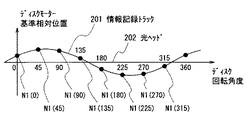
図2は、ディスクの回転角度を横軸にとった時の、情報記録トラック108の偏心、光ヘッド105の変位をグラフにしたもので、図2(a)は上記第1の回転数でディスク104を回転させた場合のグラフで、201は情報記録トラック108の偏心波形、202は光ヘッド5の変位波形であり、黒丸で示す点がトラックカウントで得られるN1(θ[i])(i=1、2、…、8)である。
Next, the measurement of the vibration amplitude using the length of the diagonal line in the case where n = 8 and the track cross pulse is measured by dividing the disk rotation angle into eight will be described.
FIG. 2 is a graph showing the eccentricity of the information recording track 108 and the displacement of the
図2(b)は上記第2の回転数でディスク104を回転させた場合のグラフで、203は情報記録トラック108の偏心波形、204は光ヘッド105の変位波形、205は情報記録トラックと光ヘッドの相対変位であり、黒丸で示す点がトラックカウントで得られるN2(θ[i])(i=1、2、…、8)である。
FIG. 2B is a graph when the disk 104 is rotated at the second rotational speed. 203 is the eccentric waveform of the information recording track 108, 204 is the displacement waveform of the
波形204はディスク104の偏重心による光ヘッド105の振動を表わしている。そして、ディスク104の回転数が変わっても情報記録トラック108の偏心の振幅と位相は変わらないので、波形203は波形201と等しい。それら二つを加算されて、情報記録トラック108と光ヘッド105の相対変位を表わしている波形205となる。図2に示すようにN1(θ[i])、N2(θ[i])は共にθ[i]を変数とする正弦波となる。両者の減算結果のM(θ[i])も正弦波となり、M(θ[i])を、大きさがM(θ[i])、位相角がθ[i]のベクトルで表わした時、その位置は原点を通る円に内接する正四角形の頂点になる。
A waveform 204 represents the vibration of the
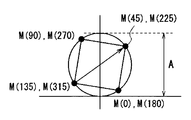
この様子を表わしたのが図3であり、図3(a)がM(θ[i])の波形を示し、図3(b)がM(θ[i])を極座標変換したときの図であり、ベクトルM(θ[i])が原点を通る円に内接する正四角形の頂点になる様子を示している。また、301は振動振幅、302は情報記録トラックと光ヘッドの相対変位である。
FIG. 3 shows this state, FIG. 3A shows a waveform of M (θ [i]), and FIG. 3B shows a diagram when M (θ [i]) is converted into polar coordinates. The vector M (θ [i]) is a regular square vertex inscribed in a circle passing through the origin.
対角線を結ぶことができる関係をもつ二つのベクトルの差、(M(θ−90),θ−90)−(M(θ+90),θ+90)(θ=0,45,90,135,180,225,270,315)を求めると、差の絶対値は上記正四角形の対角線の長さに等しくなるので、この8個の差ベクトルの絶対値の平均値を演算することにより、実際のM(θ[i])に含まれる測定誤差を低減することが出来る。又、上記正四角形の場合、対角線の長さは正弦波状に変化するM(θ[i])の振幅301に相当するので、それを用いて基台101の振動振幅を測定することが出来る。
The difference between two vectors having a relationship capable of connecting diagonal lines, (M (θ−90), θ−90) − (M (θ + 90), θ + 90) (θ = 0, 45, 90, 135, 180, 225) , 270, 315), the absolute value of the difference is equal to the length of the diagonal line of the regular square. By calculating the average value of the absolute values of the eight difference vectors, the actual M (θ Measurement errors included in [i]) can be reduced. Further, in the case of the regular square, the length of the diagonal corresponds to the
なお、本実施の形態1では第1の回転数はfoAより低く、第2の回転数はfoAより高くかつfoMより低い状況で測定を行うとしたが、foA以上の回転数ではディスク104の偏重心による遠心力が回転数の2乗に比例して増加し、また、foA以下の回転数ではディスク104と光ヘッド105との相対変位量はディスク回転数の2乗に比例して減少するため、第1の回転数、第2の回転数が共にfoAより高い、または第1の回転数、第2の回転数がともにfoAより低い状況で振動振幅の測定を行うようにしても良く、同様な効果を得ることが出来る。
In the first embodiment, the measurement is performed in a situation where the first rotational speed is lower than foA and the second rotational speed is higher than foA and lower than foM. The centrifugal force due to the heart increases in proportion to the square of the rotational speed, and the relative displacement between the disk 104 and the
なお、ディスクの複数回転分の計数データを平均処理するように構成することで、振動振幅測定の精度を向上させることができる。 It should be noted that the accuracy of vibration amplitude measurement can be improved by averaging the count data for a plurality of rotations of the disk.
なお、低い回転数から高い回転数へと複数の回転数を設け、順次回転数を切換えながら振動振幅測定を行い、ディスク104の偏重心が大きく低い回転数で大きな振動が発生した場合には、その時点で振動振幅測定を完了させ、ディスク104の偏重心が小さい場合にはより高い回転数で振動振幅測定を行うことで、発生する振動を一定以下に抑えながら、より精度の高い振動測定を行うことが出来る。逆に、高い回転数から低い回転数へと切換えながら測定を行ってもよい。 A plurality of rotation speeds are provided from a low rotation speed to a high rotation speed, and vibration amplitude is measured while sequentially switching the rotation speed. At that time, the vibration amplitude measurement is completed, and when the eccentric gravity center of the disk 104 is small, the vibration amplitude measurement is performed at a higher rotational speed, so that the vibration measurement with higher accuracy can be performed while keeping the generated vibration below a certain level. Can be done. Conversely, the measurement may be performed while switching from a high rotational speed to a low rotational speed.
なお、連続する複数の計数点或いは回転角度の計数結果をひとつにまとめて、回転角度が大きいときの計数結果とすることで、ディスク一回転の分割数を変更しても、再度の計数を行う必要や、ベクトルを演算する処理を変更する必要を無くすことができる。 In addition, even if the number of divisions for one rotation of the disk is changed, counting is performed again by combining the counting results of a plurality of consecutive counting points or rotation angles into one to obtain a count result when the rotation angle is large. It is possible to eliminate the necessity and change of the processing for calculating the vector.
このように、本実施の形態1による振動測定装置では、第1の回転数でディスクを回転させて発生したトラッククロスパルスを、ディスクの一回転をn分割し、分割した回転角度毎に計数し、そして第2の回転数でディスクを回転させて発生したトラッククロスパルスを、同様に回転角度毎に計数し、2回の計数の減算結果を、対応する回転角度を位相角、減算結果を絶対値とするベクトルで表し、該ベクトルが形成する正多角形の、対角線を結べる関係をもつベクトル間の差ベクトルを計算し、該複数の差ベクトルの絶対値の平均を求めることにより基台の振動振幅を測定するようにしたので、ディスク一回転の回転角度を任意の数に分割しても、精度よくディスク再生装置のディスク基台の振動振幅を求めることができる。これにより、分割数の基準となるモータの極数を自由に選べるため、モータの汎用化が可能となり、本発明の振動測定装置を備えた光ディスクドライブ装置は、用いるモータを幅広く選択することができる。 As described above, in the vibration measuring apparatus according to the first embodiment, the track cross pulse generated by rotating the disk at the first rotation number is divided into n rotations of the disk and counted for each divided rotation angle. The track cross pulse generated by rotating the disk at the second rotational speed is similarly counted for each rotational angle, and the subtraction result of the two counts is the phase angle of the corresponding rotational angle, and the subtraction result is absolute The base vibration is calculated by calculating a difference vector between vectors having a relation to connect diagonal lines of a regular polygon formed by the vector, and calculating an average of absolute values of the plurality of difference vectors. Since the amplitude is measured, the vibration amplitude of the disk base of the disk reproducing apparatus can be obtained accurately even if the rotation angle of one disk rotation is divided into an arbitrary number. As a result, the number of poles of the motor as a reference for the number of divisions can be freely selected, so that the motor can be used for general purposes, and the optical disk drive device equipped with the vibration measuring device of the present invention can widely select a motor to be used. .
本発明にかかる振動測定装置は、ディスク一回転の回転角度の分割数によらず振動振幅を求めることができるため、分割数の基準となるモータの極数が自由に選べるようになりモータの汎用化を可能にすることができるという効果を有し、光ディスクドライブ装置においてモータの選別の幅を広げることのできる振動測定装置として有用である。 Since the vibration measuring apparatus according to the present invention can determine the vibration amplitude regardless of the number of divisions of the rotation angle of one rotation of the disk, the number of motor poles as a reference for the number of divisions can be freely selected, and the general-purpose motor Therefore, the present invention is useful as a vibration measuring apparatus capable of widening the range of motor selection in an optical disk drive apparatus.
101 基台
102 ディスクモーター
103 インシュレーター
104 ディスク
105 光ヘッド
106 弾性材
107 光ビーム
108 情報記録トラック
109 トラッククロス検出手段
110 計数手段
111 測定手段
112 モーター制御手段
113 トラッククロス方向検出手段
114 記憶手段
115 フィルタ手段
116 ベクトル演算手段
201 情報記録トラックの偏心波形
202 光ヘッドの変位波形
203 情報記録トラックの偏心波形
204 光ヘッドの変位波形
205 情報記録トラックと光ヘッドの相対変位
301 振動振幅
302 情報記録トラックと光ヘッドの相対変位
DESCRIPTION OF
Claims (8)
上記光ヘッドから出射された光ビームが上記ディスクの上記情報記録トラックを横切る際の再生信号からトラッククロスを検出してトラッククロスパルスを発生するトラッククロス検出手段と、
上記光ヘッドから出射された光ビームが上記ディスクの上記情報記録トラックを横切る際の再生信号からトラッククロス方向を検出するトラッククロス方向検出手段と、
上記トラッククロス方向検出手段の検出結果に応じて上記トラッククロス検出手段の発生したトラッククロスパルスをディスク回転角度ごとにカウントする計数手段と、
上記ディスクモーターの回転数を設定するモーター制御手段と、
上記計数手段の計数結果をもとに上記基台の振動振幅を演算する測定手段とを備え、
前記測定手段は、第1の回転数における上記計数手段のディスク回転角度ごとの計数結果と、上記第1の回転数より高い第2の回転数における上記計数手段のディスク回転角度ごとの計数結果から求めた減算結果を、対応するディスク回転角度を位相角、該減算結果を絶対値とするベクトルで表わし、該ベクトルが形成する正m角形(mは4以上の自然数)の、対角線を結べる関係をもつベクトル間の差ベクトルを演算し、それらの差ベクトルの絶対値の平均を演算することにより前記基台の振動振幅を測定する、
ことを特徴とする振動測定装置。 A disk having information recording tracks circumferentially or spirally on the information recording surface, a disk motor for rotating the disk, and a base on which the disk motor is fixed and elastically suspended from the optical disk reproducing apparatus body A vibration measuring device for measuring vibration caused by the eccentric center of gravity of the disk, provided in an optical disk reproducing apparatus having a base and an optical head suspended from the base by an elastic material and displaceable in the radial direction of the disk. ,
Track cross detection means for generating a track cross pulse by detecting a track cross from a reproduction signal when a light beam emitted from the optical head crosses the information recording track of the disk;
Track cross direction detecting means for detecting a track cross direction from a reproduction signal when a light beam emitted from the optical head crosses the information recording track of the disk;
Counting means for counting the track cross pulses generated by the track cross detecting means for each disk rotation angle in accordance with the detection result of the track cross direction detecting means;
Motor control means for setting the rotational speed of the disk motor;
Measuring means for calculating the vibration amplitude of the base based on the counting result of the counting means,
The measuring means is based on a counting result for each disk rotation angle of the counting means at a first rotation speed and a counting result for each disk rotation angle of the counting means at a second rotation speed higher than the first rotation speed. The obtained subtraction result is represented by a vector in which the corresponding disk rotation angle is a phase angle and the subtraction result is an absolute value, and a relationship in which a diagonal line of a regular m-gon (m is a natural number of 4 or more) formed by the vector is formed. Measuring the vibration amplitude of the base by calculating the difference vector between the vectors having, and calculating the average of the absolute values of the difference vectors;
A vibration measuring apparatus characterized by that.
mは4であり、上記ディスクの一回転の回転角度を2m(=8)区分の回転角度に分割し、
上記測定手段は、上記減算結果により得られたベクトルが形成する正4角形の、対角線を結べる関係をもつベクトル間の差ベクトルを8個演算し、それらの8個の差ベクトルの絶対値の平均を演算することにより前記基台の振動振幅を測定する、
ことを特徴とする振動測定装置。 The vibration measurement device according to claim 1,
m is 4, and the rotation angle of one rotation of the disk is divided into rotation angles of 2 m (= 8) sections,
The measurement means calculates eight difference vectors between vectors having a relation of connecting a diagonal line formed by the vector obtained by the subtraction result, and averaging the absolute values of the eight difference vectors. Measure the vibration amplitude of the base by calculating
A vibration measuring apparatus characterized by that.
前記測定手段は、前記正m角形の、最長の対角線を結べる関係をもつベクトル間の差ベクトルを演算し、それらの差ベクトルの絶対値の平均を演算することにより前記基台の振動振幅を測定する、
ことを特徴とする振動測定装置。 The vibration measurement device according to claim 1,
The measuring means calculates a difference vector between vectors having the relation of connecting the longest diagonal line of the regular m-gon, and measures the vibration amplitude of the base by calculating an average of absolute values of the difference vectors. To
A vibration measuring apparatus characterized by that.
上記光ヘッドから出射された光ビームが上記ディスクの上記情報記録トラックを横切る際の再生信号からトラッククロスを検出してトラッククロスパルスを発生するトラッククロス検出手段と、
上記光ヘッドから出射された光ビームが上記ディスクの上記情報記録トラックを横切る際の再生信号からトラッククロス方向を検出するトラッククロス方向検出手段と、
上記トラッククロス方向検出手段の検出結果に応じて上記トラッククロス検出手段の発生したトラッククロスパルスをディスク回転角度ごとにカウントする計数手段と、
上記ディスクモーターの回転数を設定するモーター制御手段と、
上記計数手段の計数結果をもとに上記基台の振動振幅を演算する測定手段とを備え、
前記測定手段は、第1の回転数における上記計数手段のディスク回転角度ごとの計数結果と、上記第1の回転数より高い第2の回転数における上記計数手段のディスク回転角度ごとの計数結果から求めた減算結果を、対応するディスク回転角度を位相角、該減算結果を絶対値とするベクトルで表わし、位相角の隣接する上記ベクトル間の差ベクトルを演算し、それらの差ベクトルの絶対値の平均を演算することにより前記基台の振動振幅を測定する、
ことを特徴とする振動測定装置。 A disk having information recording tracks circumferentially or spirally on the information recording surface, a disk motor for rotating the disk, and a base on which the disk motor is fixed and elastically suspended from the optical disk reproducing apparatus body A vibration measuring device for measuring vibration caused by the eccentric center of gravity of the disk, provided in an optical disk reproducing apparatus having a base and an optical head suspended from the base by an elastic material and displaceable in the radial direction of the disk. ,
Track cross detection means for generating a track cross pulse by detecting a track cross from a reproduction signal when a light beam emitted from the optical head crosses the information recording track of the disk;
Track cross direction detecting means for detecting a track cross direction from a reproduction signal when a light beam emitted from the optical head crosses the information recording track of the disk;
Counting means for counting the track cross pulses generated by the track cross detecting means for each disk rotation angle in accordance with the detection result of the track cross direction detecting means;
Motor control means for setting the rotational speed of the disk motor;
Measuring means for calculating the vibration amplitude of the base based on the counting result of the counting means,
The measuring means is based on a counting result for each disk rotation angle of the counting means at a first rotation speed and a counting result for each disk rotation angle of the counting means at a second rotation speed higher than the first rotation speed. The obtained subtraction result is represented by a vector in which the corresponding disk rotation angle is a phase angle and the subtraction result is an absolute value, a difference vector between the adjacent vectors of the phase angle is calculated, and the absolute value of those difference vectors is calculated. Measure the vibration amplitude of the base by calculating the average,
A vibration measuring apparatus characterized by that.
前記計数手段は、180度離れた2回転角度にカウントした2つの計数結果の差が所定値より大きい場合、該1回転における全ての計数結果を破棄する、
ことを特徴とする振動測定装置。 In the vibration measuring device according to any one of claims 1 to 4,
The counting means discards all counting results in one rotation when a difference between two counting results counted at two rotation angles separated by 180 degrees is larger than a predetermined value;
A vibration measuring apparatus characterized by that.
上記計数手段は、上記ディスクの複数回転分の計数データを平均処理する、
ことを特徴とする振動測定装置。 In the vibration measuring device according to any one of claims 1 to 4,
The counting means averages the counting data for a plurality of rotations of the disk;
A vibration measuring apparatus characterized by that.
上記測定手段は、上記第1および第2の回転数における上記計数手段の計数結果に、上記第2の回転数よりも高い第3の回転数、必要に応じて複数の回転数における上記計数手段の計数結果を加えて、前記基台の振動振幅を測定する、
ことを特徴とする振動測定装置。 In the vibration measuring device according to any one of claims 1 to 4,
The measuring means includes a counting result of the counting means at the first and second rotational speeds, a third rotational speed higher than the second rotational speed, and the counting means at a plurality of rotational speeds as necessary. , And the vibration amplitude of the base is measured.
A vibration measuring apparatus characterized by that.
上記計数手段は、連続する複数の回転角度における計数結果をまとめて、前記連続する複数の回転角度より構成する1つの大きい回転角度における計数結果とする、
ことを特徴とする振動測定装置。 In the vibration measuring device according to any one of claims 1 to 4,
The counting means summarizes the counting results at a plurality of continuous rotation angles, and sets the counting results at one large rotation angle constituted by the plurality of continuous rotation angles.
A vibration measuring apparatus characterized by that.
Priority Applications (1)
| Application Number | Priority Date | Filing Date | Title |
|---|---|---|---|
| JP2004110477A JP2005292056A (en) | 2004-04-02 | 2004-04-02 | Vibration measuring device |
Applications Claiming Priority (1)
| Application Number | Priority Date | Filing Date | Title |
|---|---|---|---|
| JP2004110477A JP2005292056A (en) | 2004-04-02 | 2004-04-02 | Vibration measuring device |
Publications (1)
| Publication Number | Publication Date |
|---|---|
| JP2005292056A true JP2005292056A (en) | 2005-10-20 |
Family
ID=35325134
Family Applications (1)
| Application Number | Title | Priority Date | Filing Date |
|---|---|---|---|
| JP2004110477A Pending JP2005292056A (en) | 2004-04-02 | 2004-04-02 | Vibration measuring device |
Country Status (1)
| Country | Link |
|---|---|
| JP (1) | JP2005292056A (en) |
-
2004
- 2004-04-02 JP JP2004110477A patent/JP2005292056A/en active Pending
Similar Documents
| Publication | Publication Date | Title |
|---|---|---|
| KR100454798B1 (en) | Information disc recording/playback apparatus, and vibration detection method for information disc recording/playback apparatus | |
| US6304528B1 (en) | Optical disk reproducing apparatus | |
| CN110568421B (en) | Method for measuring deflection angle of scanning galvanometer and laser radar using same | |
| US7436146B2 (en) | Stepping motor speed control method and apparatus suitable for the same | |
| JP2005292056A (en) | Vibration measuring device | |
| CN115135962B (en) | Method and apparatus for zero-g offset calibration of MEMS-based accelerometers | |
| JP2000113581A (en) | Optical disc playback device | |
| JP4204245B2 (en) | Information disc recording / reproducing apparatus and recording / reproducing speed control method therefor | |
| JP2004219333A (en) | Encoder output signal correction device | |
| US8610392B2 (en) | Runout measurement for devices having a rotating body | |
| JP4848513B2 (en) | Rotating body measuring method and apparatus | |
| KR100619690B1 (en) | Mass imbalance detection method of disk media | |
| JP6513327B2 (en) | Length measuring device and origin position detection method | |
| JP4554115B2 (en) | Information disc recording / reproducing device | |
| JP5355773B2 (en) | Disk unit | |
| JP2004241114A (en) | Information disc recording / reproducing apparatus and vibration detection method for information disc recording / reproducing apparatus | |
| JPH09145734A (en) | Speed detector | |
| JP2019074397A (en) | Angle detector, angle detection method, and program | |
| CN117686739A (en) | Dynamic angular acceleration measuring and evaluating method | |
| Jiang et al. | Accurate runout measurement for HDD spinning motors and disks | |
| JP2007010358A (en) | Rotational displacement measuring instrument with effect of vibration on rotary machine removed therefrom and its measuring method | |
| JP2000182316A (en) | Disk driving device | |
| JPH10162393A (en) | Optical disk device | |
| JP2002251749A (en) | Optical disk drive | |
| JP2001216717A (en) | Tilt evaluation device and evaluation method |